2A9JBT2dash camera
Shenzhen Phisung Video Technology Co., Ltd.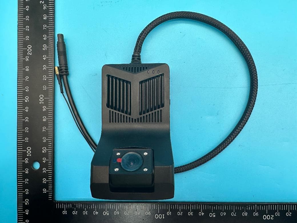
Click to zoom
Application Details
- Equipment Class
- DTS - Digital Transmission System
- Date of Grant
- Mar 05, 2023
- Application Purpose
- Original Equipment
- Date of Application
- Mar 05, 2023
- Equipment Note
- dash camera
- Frequency Range
- 2412.00000000 - 2462.00000000
- Country
- China
Documents & Files
Document Text
Text extracted from the exhibit documents filed with the FCC. Open a document above to read the original.
Users Manual
4G SmartVision Dash Camera User Manual Part 1. Product Overview This device is a 4G dual channels ( Front cam+IR night vision inside camera) driving recorder, with high-definition, ADAS, one-button alarm, GPS driving track & position, WiFi hotspot, 4G internet surfing and Android systems. It could meet with JT / T1078 “ Road Transport Vehicle Satellite Positioning System Video Communication Protocol “ and JT/ T808 “Road Transport Vehicle Satellite Position System BeiDou Compatible Vehicle Terminal Communication Protocol Technical Specifications” hardware requirements. Part 2. Product Installation ① Power BMW wire ② GPS connector ③ SOS button and Power connector ④ SOS alarm button ⑤ Yellow wire BAT + connector ⑥ Black wire GND connector ⑦ Red wire ACC connector ■ How to install the device? Step 1. Please ensure you close the car engine. Step2. Use the screwdriver to open the lockable SIM & TF card cover, and then insert the SIM card and TF card by correct direction as below: Step 3. Connect well the GPS antenna and power cable with device. Step 4. Please fix the camera via the 3M holder onto the windshield. Step 5. Open the vehicle fuse box, connect the power cable ‘s other side with vehicle battery as below: Red wire connect with vehicle battery ‘s ACC (12V+ after we start the car engine) ; Yellow wire connect with BAT+ (12V power after we close the car engine ); Black wire connect with GND(find a reliable iron part to connect to the ground). Step 6. After connecting the power, device’s Red Light will be on. Remarks: it will take about 3 minutes to power on device, please don’t cut off the power during this period. The indicator lights , please refer to below working indicator lights introduction. Step 7. Start the car engine to check if the camera installation correctly. Step 8. Open the CarAssist APP, and adjust the camera position to ensure image recorded in the center of display . Part 3. Product introduction 1. Working Indicator Lights Blue light--> GPS status indicator light: After device switch on, blue light is always on when GPS located; blue light flickers when GPS is not positioning. Green light-->REC status indicator light: After device switch on, green light slowly flickers when recording; green light is off when the device is not recording. Please check whether insert the memory card. Red light-->4G network status indicator light: After device switch on, red light is always on if 4G signal searched; If the red light is off , it means the device could not identify the SIM card or 4G signal is not good. Please insert the SIM card again. Red +Green light quickly flashing means, the device is under recovering to the factory default settings process. Red light and Blue light is always on, the green light is slowly flashing , it means , the device work normally . 2. Power / OK button Short press it to broadcast device’s WIFI hotspot name and device working status. Long press it to restart the device; Long press it until the device power off , and then Red led and Green led light up at the same time, it means, device is under recovering to the factory default settings. One-Key alarm button, short press it to upload photos to the platform / mobile APP. 3. External Memory Card Support Please use the 16GB-128GB high speed Class 10 Micro SD card. Please format the memory card firstly before insert to the device. 4. Car Video Recording Functions Device runs and records automatically after car engine is on. Front camera is FHD 1080P, inside camera is 720P. The inside camera is with light sensor & IR night vision, produces crystal clear video to know events inside the car even if at low light condition. Seamless loop recording overwrites the oldest footage with the newest upon filling a card to capacity. Variable sensitivity G-sensor auto detects a sudden shake/collision and emergency locks the footage to "Event File" to prevent that video from an overwrite. About car dvr settings, please bind the device with your smart phone, and go to the CarAssist app to set up the dvr settings. 5. Parking Monitor The camera will be automatically enter parking sleep mode after car engine is off . The camera will automatically send alarm message, and capture and upload the photo to the mobile APP with location information if sudden shake / collision happened to the vehicle. You could use the mobile app : CarAssist app to remote monitor this dash camera by remote capture , live view , remote recording, remote talk functions. About the CarAssist app operation, please refer to the next part: CarAssist Mobile APP. In order to protect your car battery, this device will automatically shut down when detect the vehicle is under low voltage status. 6. FAQ Product Questions Solutions 1.The 3M holder could not firmly attached to the windshield? Please check and ensure the car windshield is clean. And Air between the 3M adhesive and glass is squeezed out and press firmly. 2. The body of camera shakes, and the video is skewed? Please ensure the camera and 3M holder is fastened well. 3.The video is not clear and dark? Please ensure the camera lens or the car windshield is clean , and camera lens’s shooting angle should not be too high. 4. The parking monitor function could not work? Please check whether you connect well the power cable by correct sequence, yellow wire connect with BAT+ Long battery 12V , the Red wire connect with ACC12V. 5.The device could not be power on or normal working? Please check whether connect well the power cable; Please check whether the wire fuse is intact; . Please use needle to short click the RESET hole to restart the device ; Or long press the power button to recover to the factory default settings. 6. The Red Led could not light up? Please check whether insert well the SIM card And whether the SIM card has enough traffic Data. 7.The Blue Led is blinking? Please check whether connect well the GPS antenna, and test it outdoor. 8.The Green Le…
Text truncated - open the document above for the full version.
Cover Letter(s)
Shenzhen Phisung Video Technology Co., Ltd. 2023.2.28 Eurofins Electrical and Electronic Testing NA, Inc. 914 West Patapsco Avenue Baltimore, MD 21230 RE: LETTER OF AGENT AUTHORIZATION To Whom It May Concern: We, the undersigned, hereby authorize (Shenzhen LGT Test Service Co., Ltd.) to act on our behalf in all matters relating to application for equipment authorization, including the signing of all documents relating to these matters. We also hereby certify that no party to the application authorized hereunder is subject to the denial of benefits, including FCC benefits, pursuant to Section 5301 of the Anti-Drug Abuse Act of 1988, 21 U.S.C.853(a). This agreement expires one year from the current date. Sincerely, Signature: Date: 2023. 02.28 Name: Luodaoping Title: Manager Company: Shenzhen Phisung Video Technology Co., Ltd.
Cover Letter(s)
Shenzhen Phisung Video Technology Co., Ltd. Office of Engineering Technology Federal Communications Commission 7435 Oakland Mills Road Columbia, MD 21046 USA Date: 2023.2.28 Subject; Request for Confidentiality FCC ID: 2A9JBT2 To Whom It May Concern, Pursuant to the provisions of the Commission’s rules Title 47 Sections §0.457 and §0.459, we are requesting the Commission to withhold the following attachment(s) as confidential documents from public disclosure indefinitely. These documents contain detailed system and equipment descriptions and are considered as proprietary information in operation of the equipment. The public disclosure of these documents might be harmful to our company and would give competitors an unfair advantage in the market. Schematic Diagram Block Diagram Operational Description Tune-up Procedure Part List PCB layout In additional to above mentioned documents, in order to comply with the marketing regulations in Title 47 CFR §2.803 and the importation rules in Title 47 CFR §2.1204, while ensuring that business sensitive information remains confidential until the actual marketing of newly authorized devices, we request Short Term Confidentiality of the following attachment(s); External Photos Test Setup Photos Internal Photos User Manual For 45 days, pursuant to Public Notice DA 04-1705. OR For 180 days pursuant to KDB 726920 D01. It is our understanding that all measurement test reports, FCC ID label format and correspondence during the certification review process cannot be granted as confidential documents and this information will be available for public review once the grant of equipment authorization is issued. Sincerely, Signature: Name: Luodaoping/Shenzhen Phisung Video Technology Co., Ltd. Title: Manager
External Photos
Page 1 of 5 Report No.: LGT22K057 Appendix - External Photographs of EUT Constructional Details FCC ID: 2A9JBT2 Model Name: T2 Photo 1 Photo 2 Page 2 of 5 Report No.: LGT22K057 Photo 3 Photo 4 Page 3 of 5 Report No.: LGT22K057 Photo 5 Photo 6 Page 4 of 5 Report No.: LGT22K057 Photo 7 Photo 8 Page 5 of 5 Report No.: LGT22K057 Photo 9 Photo 10
ID Label/Location Info
FCC Label 4G dash camera Model name: T2 FCC ID:2A9JBT2 Made in China
Internal Photos
Page 1 of 7 Report No.: LGT22K057 Appendix - Internal Photographs of EUT Constructional Details FCC ID: 2A9JBT2 Model Name: T2 Photo 1 Photo 2 Page 2 of 7 Report No.: LGT22K057 Photo 3 Photo 4 Page 3 of 7 Report No.: LGT22K057 Photo 5 Photo 6 Page 4 of 7 Report No.: LGT22K057 Photo 7 Photo 8 WIFI ANT Page 5 of 7 Report No.: LGT22K057 Photo 9 Photo 10 Page 6 of 7 Report No.: LGT22K057 Photo 11 Photo 12 Page 7 of 7 Report No.: LGT22K057 Photo 13 2G/3G/4 G ANT
RF Exposure Info
RF Exposure Report FCC-ID: 2A9JBT2 RF Exposure Measurement The limit for Maximum Permissible Exposure (MPE) specified in FCC 1.1310 is followed. The gain of the antennas used in the product is extracted from the Antenna data sheets provided and also the maximum total power input to the antenna is measured. Through the Friis transmission formula and the maximum gain of the antenna, we can calculate the distance, away from the product, where the limit of MPE is reached. Although the Friis Transmission formula is far field assumption, the calculated result of that is an over-prediction for near field power density. It is taken as worst case to specify the safety range. RF Exposure Limit According to FCC 1.1310: The criteria listed in the following table shall be used to evaluate the environmental impact of the human exposure to radio-frequency (RF) radiation as specified in 1.1307 (b) Limits for Maximum Permissible Exposure (MPE) F= Frequency in MHz Frequency Range (MHz) Electric Field Strength (V/m) Magnetic Field Strength (A/m) Power Density (mW/cm²) Limits for Occupational / controlled Exposures 300 - 1500 -- -- F/300 1500 – 100000 -- -- 5.0 Limits for General population / Uncontrolled Exposure 300 - 1500 -- -- F/1500 1500 – 100000 -- -- 1.0 Friss Formula Friss Transmission Formula: Pd = (Pout * G) / (4*pi*r²) Where Pd = power density in mW/cm² Pout = output power to antenna in mW G = gain of antenna in linear scale Pi = 3.1416 R = Distance between observation point and the center of radiator in cm If we know the maximum gain of the antenna and the total output power to the antenna, through calculation, we will know MPE value at distance 20cm. EUT Operation condition EUT was enabled to transmit and receive at lowest, middle and highest channels. Classification The antenna of this product, under normal use condition, is at least 20cm away from the body of the user. Warning statement to the user for keeping at least 20cm or more separation distance from the antenna should be included in the User manual. So, this device is classified as Mobile device. 2.4G WIFI Mode 802.11b/g/n20:2412-2462MHz 802.11n40:2422-2452MHz Detector PEAK 802.11b 13±1dBm 802.11g 13.5±1dBm 802.11n20 13.5±1dBm 802.11n40 13.5±1dBm ANT Gain (G) Antenna gain : 2.62dBi (gain of antenna in linear scale=1.828) 802.11 b 1.828 2412 14 25.1189 0.00914 1 802.11 g 1.828 2462 14.5 28.1838 0.01025 1 802.11 n20 1.828 2462 14.5 28.1838 0.01025 1 802.11 n40 1.828 2452 14.5 28.1838 0.01025 1 Power Density (mW/cm²) Limit (mW/cm²) ANT Gain(gain of antenna in linear scale) Protocol Channel Frequency (MHz) Output Power to Antenna (dBm) Output Power to Antenna (mW) GPRS/EGPRS/WCDMA Mode GPRS/EGPRS: Band V: 824 MHz ~ 849 MHz Band II: 1850 MHz ~ 1910 MHz WCDMA Band V: 824 MHz ~ 849 MHz Detector PEAK GPRS850 32.5±1dBm GPRS1900 29.5±1dBm EGPRS850 29.5±1dBm EGPRS1900 31±1dBm WCDMA850 23±1dBm ANT Gain (G) GPRS/EGPRS 850 Antenna gain : -0.66dBi (gain of antenna in linear scale=0.859) GPRS/EGPRS 1900 Antenna gain : 0.29dBi (gain of antenna in linear scale=1.069) WCDMA 850 Antenna gain : -0.66dBi (gain of antenna in linear scale=0.859) GPRS850 0.859 846.8 33.5 2238.7211 0.38277 1 GPRS1900 1.069 1880 30.5 1122.0185 0.23874 1 EGPRS850 0.859 848.8 30.5 1122.0185 0.19184 1 EGPRS1900 1.069 1850.2 32 1584.8932 0.33723 1 WCDMA850 0.859 846.6 24 251.1886 0.04295 1 Power Density (mW/cm²) Limit (mW/cm²) ANT Gain(gain of antenna in linear scale) Protocol Channel Frequency (MHz) Output Power to Antenna (dBm) Output Power to Antenna (mW) LTE Mode LTE Band 4:1710~1755MHz LTE Band 5:824~849MHz LTE Band 38:2570~2620MHz LTE Band 40:2305~2315MHz/2350~2360MHz LTE Band 41:2555~2655MHz Detector PEAK LTE Band 4 23±1dBm LTE Band 5 23.5±1dBm LTE Band 38 21±1dBm LTE Band 40 (2305~2315) 22±1dBm LTE Band 40 (2350~2360) 22±1dBm LTE Band 41 23±1dBm ANT Gain (G) Band 4 Antenna gain : 0.41dBi (gain of antenna in linear scale=1.099) Band 5 Antenna gain : -0.66dBi (gain of antenna in linear scale=0.859) Band 38 Antenna gain : 1.59dBi (gain of antenna in linear scale=1.442) Band 40(2305-2315) Antenna gain : 0.73dBi (gain of antenna in linear scale=1.183) Band 40 (2350-2360) Antenna gain : 0.28dBi (gain of antenna in linear scale=1.066) Band 41 Antenna gain : 2.93dBi (gain of antenna in linear scale=1963) LTE Band 41.099185024251.18860.054951 LTE Band 50.859171024.5281.83830.061651 LTE Band 381.44282422158.48930.045491 LTE Band 401.18369923199.52620.046981 LTE Band 401.06677723199.52620.042341 LTE Band 411.96370424251.18860.098151 Power Density (mW/cm²) Limit (mW/cm²) ANT Gain(gain of antenna in linear scale) Protocol Channel Frequency (MHz) Output Power to Antenna (dBm) Output Power to Antenna (mW)
Test Report
深圳市宝安区西乡街道固戍上围园新园工业区A1栋3楼 电话:0755-27492635传真:0755-27471559 HTTP://WWW.yunxikeji.COM 第 1 页 天线规格书 Antennaspecificationforapproval 客户名称:普联机型:TW-1 天线类型:4G主天线/4G副天线 天线频段:LTE:1/3/5+WCDMA:2100 材质要求:FPC颜色:黑色 4G主天线:G1576A-1L22B-085-A 4G副天线:G1085B-1D22B-080-A制作日期:2020-04-29 Version:A 承认签章 Admitthatsignature 云希承认 ConfirmationSignature 客户承认 CustomerApproved 承辦人Responsible承辦人Responsible 品质QC主管Chief 核准Approve核准Approve 日期 Date 日期 Date 深圳市宝安区西乡街道固戍上围园新园工业区A1栋3楼 电话:0755-27492635传真:0755-27471559 HTTP://WWW.yunxikeji.COM 第 2 页 目录 封面 ...................................................................................1 目录..................................................................... 2 一概述 --------------------------------------------------------------3 二匹配电路图、机器图、天线图-------------------------------3-4 三 3D数据--------------------------------------------------------------5 四结构图纸 ---------------------------------------------------------6-7 深圳市宝安区西乡街道固戍上围园新园工业区A1栋3楼 电话:0755-27492635传真:0755-27471559 HTTP://WWW.yunxikeji.COM 第 3 页 一:概述 ●ThisapprovalsheetsupportsforMIDproject.FPCantennasincludeinthisproject.Thisreportisforthe performanceof4Gantenna. ●Antennashapesize:MeettherequirementofMID ●Antennaband:824MHz~960MHz,1710MHz~2700MHz ●Antennamaterial:AntennamaterialmeettherequirementofMID ●Adhesiveperformance:AdhesiveperformancemeettherequirementofMID ●Antennaperformancemeetthespecbelow: Description 824MHz~960MHz,1710MHz~2700MHz Units VSWR ≤ 5.0 ≤ 5 AverageAntennaGain ≥-4.5≥-4.0 dB AntennaEfficiency ≥ 30 ≥ 40 % FeedImpedance50ohms OperatingTemperature-40to+85degC Polarization/AzimuthLinear/Omni-directional ●MechanicalInformation 二:匹配电路图 、 机器图片 、 天线图片 2.1匹配电路图 我司未对天线匹配做修改 MechanicalDimension CableLength085/080mm/Black Description4Gantenna MaterialFPC CoaxialCable50Ohm/0.D.0.81mm Environmental OperationTemperature-40to+85degC StorageTemperature-40to+85degC Antenna RFModule E 1 E 2 E 3 E 4 深圳市宝安区西乡街道固戍上围园新园工业区A1栋3楼 电话:0755-27492635传真:0755-27471559 HTTP://WWW.yunxikeji.COM 第 4 页 2.2机器图片、天线图片 深圳市宝安区西乡街道固戍上围园新园工业区A1栋3楼 电话:0755-27492635传真:0755-27471559 HTTP://WWW.yunxikeji.COM 第 5 页 深圳市宝安区西乡街道固戍上围园新园工业区A1栋3楼 电话:0755-27492635传真:0755-27471559 HTTP://WWW.yunxikeji.COM 第 6 页 深圳市宝安区西乡街道固戍上围园新园工业区A1栋3楼 电话:0755-27492635传真:0755-27471559 HTTP://WWW.yunxikeji.COM 第 7 页 深圳市宝安区西乡街道固戍上围园新园工业区A1栋3楼 电话:0755-27492635传真:0755-27471559 HTTP://WWW.yunxikeji.COM 第 8 页 深圳市宝安区西乡街道固戍上围园新园工业区A1栋3楼 电话:0755-27492635传真:0755-27471559 HTTP://WWW.yunxikeji.COM 第 9 页 深圳市宝安区西乡街道固戍上围园新园工业区A1栋3楼 电话:0755-27492635传真:0755-27471559 HTTP://WWW.yunxikeji.COM 第 10 页 三:3D数据 深圳市宝安区西乡街道固戍上围园新园工业区A1栋3楼 电话:0755-27492635传真:0755-27471559 HTTP://WWW.yunxikeji.COM 第 11 页 四:4G主天线 深圳市宝安区西乡街道固戍上围园新园工业区A1栋3楼 电话:0755-27492635传真:0755-27471559 HTTP://WWW.yunxikeji.COM 第 12 页 4G副天线
Test Report
The test report is effective only with both signature and specialized stamp. This report shall not be reproduced except in full without the written approval of the Laboratory. The results in this report only apply to the tested sample. Shenzhen LGT Test Service Co., Ltd. Tel: 0755-89668180 E-mail:[email protected] Web: www.lgt-cert.com Room 205, Building 13, Zone B, Chen Hsong Industrial Park, No.177 Renmin West Road, Jinsha Community, Kengzi Street, Pingshan New District, Shenzhen, China RF TEST REPORT Product Name: dash camera Model Name: T2, T3, ZW2, ZW3, T88, T99, K20, E09Plus FCC ID: 2A9JBT2 Issued For : Shenzhen Phisung Video Technology Co., Ltd. 7th Floor, A Block, Ruixiangfa Science & Technology Park, Shenzhen, Guangdong, China Issued By : Shenzhen LGT Test Service Co., Ltd. Room 205, Building 13, Zone B, Chen Hsong Industrial Park, No.177 Renmin West Road, Jinsha Community, Kengzi Street, Pingshan New District, Shenzhen, China Report Number: LGT22K057RF01 Sample Received Date: Nov. 24, 2022 Date of Test: Nov. 24, 2022 – Jan. 05, 2023 Date of Issue: Jan. 05, 2023 Report No.: LGT22K057RF01 Page 2 of 69 TEST REPORT CERTIFICATION Applicant Shenzhen Phisung Video Technology Co., Ltd. Address 7th Floor, A Block, Ruixiangfa Science & Technology Park, Shenzhen, Guangdong, China Manufacturer Shenzhen Phisung Video Technology Co., Ltd. Address 7th Floor, A Block, Ruixiangfa Science & Technology Park, Shenzhen, Guangdong, China Product Name dash camera Trademark N/A Model Name T2, T3, ZW2, ZW3, T88, T99, K20, E09Plus Sample Status: Normal APPLICABLE STANDARDS STANDARD TEST RESULTS FCC Part 15.247, Subpart C ANSI C63.10-2013 PASS Prepared by: Approved by: Zane Shan Vita Li Engineer Technical Director Report No.: LGT22K057RF01 Page 3 of 69 Table of Contents Page 1. SUMMARY OF TEST RESULTS 6 1.1 TEST FACTORY 7 1.2 MEASUREMENT UNCERTAINTY 7 2. GENERAL INFORMATION 8 2.1 GENERAL DESCRIPTION OF THE EUT 8 2.2 DESCRIPTION OF THE TEST MODES 10 2.3 TEST SOFTWARE AND POWER LEVEL 11 2.5 EQUIPMENTS LIST FOR ALL TEST ITEMS 12 3. EMC EMISSION TEST 13 3.1 CONDUCTED EMISSION MEASUREMENT 13 3.2 RADIATED EMISSION MEASUREMENT 15 4. CONDUCTED SPURIOUS & BAND EDGE EMISSION 32 4.1 LIMIT 32 4.2 TEST PROCEDURE 32 4.3 DEVIATION FROM STANDARD 32 4.4 TEST SETUP 32 4.5 EUT OPERATION CONDITIONS 32 4.6 TEST RESULTS 32 5. POWER SPECTRAL DENSITY TEST 33 5.1 LIMIT 33 5.2 TEST PROCEDURE 33 5.3 DEVIATION FROM STANDARD 33 5.4 TEST SETUP 33 5.5 EUT OPERATION CONDITIONS 33 5.6 TEST RESULTS 33 6. BANDWIDTH TEST 34 6.1 LIMIT 34 6.2 TEST PROCEDURE 34 6.3 DEVIATION FROM STANDARD 34 6.4 TEST SETUP 34 6.5 EUT OPERATION CONDITIONS 34 6.6 TEST RESULTS 34 Report No.: LGT22K057RF01 Page 4 of 69 Table of Contents Page 7. PEAK OUTPUT POWER TEST 35 7.1 LIMIT 35 7.2 TEST PROCEDURE 35 7.3 DEVIATION FROM STANDARD 35 7.4 TEST SETUP 35 7.5 EUT OPERATION CONDITIONS 35 7.6 TEST RESULTS 35 8. ANTENNA REQUIREMENT 36 8.1 STANDARD REQUIREMENT 36 8.2 EUT ANTENNA 36 APPENDIX I:TEST RESULTS 37 DUTY CYCLE 37 MAXIMUM PEAK CONDUCTED OUTPUT POWER 42 -6DB BANDWIDTH 43 MAXIMUM POWER SPECTRAL DENSITY LEVEL 48 BAND EDGE 53 CONDUCTED RF SPURIOUS EMISSION 60 APPENDIX II:PHOTOS OF TEST SETUP 69 Report No.: LGT22K057RF01 Page 5 of 69 Revision History Rev. Issue Date Contents 00 Jan. 05, 2023 Initial Issue Report No.: LGT22K057RF01 Page 6 of 69 1. SUMMARY OF TEST RESULTS Test procedures according to the technical standards: KDB 558074 D01 15.247 Meas Guidance v05r02. FCC Part 15.247,Subpart C Standard Section Test Item Judgment Remark 15.207 Conducted Emission N/A -- 15.247 (a)(2) 6dB Bandwidth PASS -- 15.247 (b)(3) Output Power PASS -- 15.209 Radiated Spurious Emission PASS -- 15.247 (d) Conducted Spurious & Band Edge Emission PASS -- 15.247 (e) Power Spectral Density PASS -- 15.205 Restricted Band Edge Emission PASS -- Part 15.247(d)/ Part 15.209(a) Band Edge Emission PASS -- 15.203 Antenna Requirement PASS -- NOTE: (1) ‘N/A’ denotes test is not applicable in this Test Report. (2) All tests are according to ANSI C63.10-2013. Report No.: LGT22K057RF01 Page 7 of 69 1.1 TEST FACTORY Company Name: Shenzhen LGT Test Service Co., Ltd. Address: Room 205, Building 13, Zone B, Chen Hsong Industrial Park, No.177 Renmin West Road, Jinsha Community, Kengzi Street, Pingshan New District, Shenzhen, China Accreditation Certificate A2LA Certificate No.: 6727.01 FCC Registration No.: 746540 CAB ID: CN0136 1.2 MEASUREMENT UNCERTAINTY The reported uncertainty of measurement y ± U, where expended uncertainty U is based on a standard uncertainty multiplied by a coverage factor of k=2, providing a level of confidence of approximately 95 %. No. Item Uncertainty 1 RF Output Power, Conducted ±0.71dB 2 Power Spectral Density, Conducted ±1.57 dB 3 Unwanted Emission, Conducted ±0.63dB 4 Conducted emission ±2.80dB 5 All Emissions, Radiated (0.009-30MHz) ±2.16dB 6 All Emissions, Radiated (30MHz-1GHz) ±4.40dB 7 All Emissions, Radiated (1GHz-18GHz) ±5.49dB Report No.: LGT22K057RF01 Page 8 of 69 2. GENERAL INFORMATION 2.1 GENERAL DESCRIPTION OF THE EUT Product Name dash camera Trademark N/A Model Name T2 Series Model T3, ZW2, ZW3, T88, T99, K20, E09Plus Model Difference The differences between different models are the same except for the name of the model (to distinguish different sales regions) Product Description The EUT is a dash camera Operation Frequency: 802.11b/g/n: 2412~2462 MHz 802.11n (40MHz):2422~2452MHz Modulation Type: 802.11b(DSSS):CCK,DQPSK,DBPSK 802.11g(OFDM):BPSK,QPSK,16-QAM,64-QAM 802.11n(OFDM):BPSK,QPSK,16-QAM,64-QAM Number of Channel: 802.11b/g/n: 11CH 802.11n: 7CH Antenna Designation: FPC Antenna Antenna Gain(dBi): 2.62 Channel List Please refer to the Note 2. Rating Input: DC 12V Output: DC 5V Battery N/A Hardware version N/A Software version full_FX_T2_PL_TW1S-V1.5_4G_EN_3.0.10 Connecting I/O Port(s) Please refer to the Note 1. Note: 1. For a more detailed features description, please refer to the manufacturer’s specifications or the User Manual. Report No.: LGT22K057RF01 Page…
Text truncated - open the document above for the full version.
Test Setup Photos
Page 1 of 1 Report No.: LGT22K057 Appendix - Test Setup photos Radiated Spurious Emission Test Setup Photo - Below 1GHz Radiated Spurious Emission Test Setup Photo - Above 1GHz
Contact Information
Applicant
Luo daoping
Technical Contact
Shenzhen LGT Test Service Co., Ltd.Vita Li
[email protected]+86-0755 89668180
room 205, Building 13, Zone B, Chen Hsong Industri · Shenzhen · China
Non-Technical Contact
Shenzhen LGT Test Service Co., Ltd.Wen Wen
[email protected]+86-0755 89668180
Test Firm
Shenzhen LGT Test Service Co., Ltd.Wen Wen
[email protected]0755-89668180
Technical Specifications
| # | Rule Parts | Frequency Range | Power Output |
|---|---|---|---|
| 1 | 15C | 2.41 GHz - 2.46 GHz | 27.10 mW |