2A9KBDLM191695Wireless Transceiver
Drum Workshop, Inc.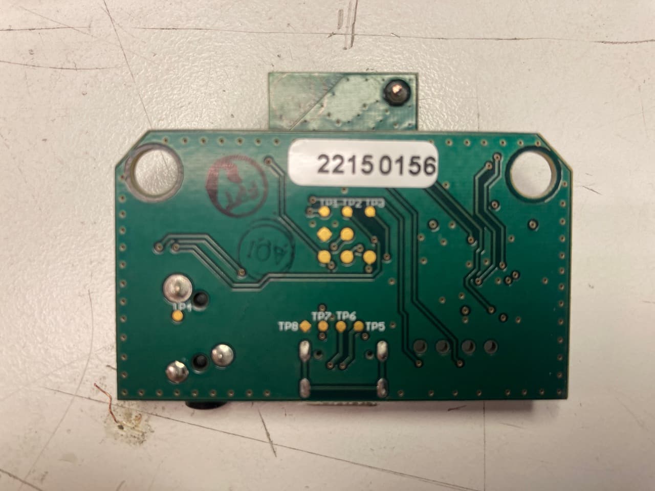
Click to zoom
Application Details
- Equipment Class
- DTS - Digital Transmission System
- Date of Grant
- Jan 15, 2023
- Application Purpose
- Original Equipment
- Date of Application
- Jan 15, 2023
- Equipment Note
- Wireless Transceiver
- Frequency Range
- 2402.00000000 - 2480.00000000
- Company
- Drum Workshop, Inc.
- Country
- United States
Documents & Files
Document Text
Text extracted from the exhibit documents filed with the FCC. Open a document above to read the original.
Users Manual
DW Drums 3450 Lunar Ct Oxnard, CA 93030 800-453-7867 www.dwdrums.com DRUM WORKSHOP INC Module Integration Instructions for Module DWE-DLM-1 FCC ID: 2A9KBDLM191695 & IC ID:29868-191695 Regulatory Compliance This section summarizes the responsibilities and actions required of the manufacturer (Drum Workshop) to incorporate the DWE-DLM-1 module device into their products. In certain situations, and applications, these “Host” products will require additional FCC, ISED or other regulatory approvals prior to sale or operation. Appropriate instructions, documentation and labels are required for all products. For more information concerning regulatory requirements, please contact Drum Workshop and or a regulatory test lab. FCC Certification and Important Information for the Integration of Module This module has been granted limited modular approval. Drum Workshop is the only authorized manufacture that can use this module for integration in to the following final DWe products, DWE-DT1, DWE-CT1 & DWE-DH1, if they meet the following conditions; • The host product with the module installed must be evaluated for simultaneous transmission requirements. • The user’s manual for the host product must clearly indicate the operation requirements and conditions that must be observed to ensure compliance with current FCC/ISED RF exposure guidelines. • A label must be affixed to the outside of the host product that includes the following statement o “Contains FCC ID: 2A9KBDLM191695” o “Contains IC ID: 29868-191695” o Along with the appropriate host name The DWE-DLM1 module has been tested under FCC Part 15 Subpart C 15.247 for Intentional Radiator, FCC CFR 47 Part 15 Subpart B for Unintentional Radiators, FCC CFR 47 Part 1.1310 for MPE/RF Exposure and KDB 558074 D01 v05r02 for compliance on DTS, FHSS, HSD operating under section 15.247. All testing has confirmed compliance with the above stated regulations. Drum Workshop has not approved any changes or modifications to this device by the end user. Any changes or modifications could void the user’s authority to operate the device/host. FCC Module Labeling If the FCC ID of the module is not visible when installed in the host platform, then a permanently attached or marked label must be displayed on the host unit it’s self-referring to the module as; • “Contains FCC ID: 2A9KBDLM191695” DW Drums 3450 Lunar Ct Oxnard, CA 93030 800-453-7867 www.dwdrums.com Also listed in the end user manual the following statement should be placed. This device complies with Part 15 of the FCC Rules. Operation is subject to the following two conditions: (1) This device may not cause harmful interference, and (2) This device must accept any interference received, including interference that may cause undesired operation. End Product Labeling for FCC: When the module is installed in the host device, the FCC/IC ID label must be visible through a window on the final device or it must be visible when an access panel, door or cover is easily re-moved. If not, a second label must be placed on the outside of the final device that contains the following text: “Contains FCC ID: 2A9KBDLM191695” FCC Part 15 Statement (Only Include if FCC Part 15 is Required on the End Product): Note: This equipment has been tested and found to comply with the limits for a (OEM to insert device type: Class A or Class B) digital device, pursuant to Part 15 of the FCC Rules. (OEM must follow Part 15 guidelines (§15.105 and §15.19) to determine additional statements required in this section for their device class) Radiation Exposure Statement for FCC: This device complies with FCC radiation exposure limits set forth for an uncontrolled environment. In order to avoid the possibility of exceeding the FCC radio frequency exposure limits, human proximity to the antenna shall not be less than 20cm (8 inches) during normal operation. This transmitter must not be co-located or operating in conjunction with any other antenna or transmitter. This device complies with Part 15 of the FCC Rules. Operation is subject to the following two conditions: (1) This device may not cause harmful interference, and (2) this device must accept any interference received, including interference that may cause undesired operation. ISED Statement and Labeling: This device complies with ISED’s license-exempt RSSs. Operation is subject to the following two conditions: (1) This device may not cause harmful interference, and (2) this device must accept any interference received, including interference that may cause undesired operation. Le présent appareil est conforme aux CNR d’ ISED applicables aux appareils radio exempts de licence. L’exploitation est autorisée aux deux conditions suivantes : (1) le dispositif ne doit pas produire de brouillage préjudiciable, et (2) ce dispositif doit accepter tout brouillage reçu, y compris un brouillage susceptible de provoquer un fonctionnement indésirable. A label containing the ISED Certification number must be permanently affixed to the exterior of the host device into which the DWE-DLM1 module device is installed. The label may also be under a panel or battery pack if it is readily accessible and cannot be separated from the host device itself. The label must contain a statement similar to the following; “Contains IC: 29868-191695” and show appropriate host name. DW Drums 3450 Lunar Ct Oxnard, CA 93030 800-453-7867 www.dwdrums.com Important Safety Information The following information applies to the devices described in this manual. Always observe all standard and accepted safety precautions and guidelines when handling any electrical device. • Save this manual: it contains important safety information. • Do not expose the DWE-DLM1product to open flames. • Ensure that liquids do not spill on to the devices. • Do not attempt to disassemble the product: Doing so will void the warranty. This product does not contain consumer-serviceable components. Product Overview The DWE-DLM1 transceiver module can …
Text truncated - open the document above for the full version.
Cover Letter(s)
DW Drums 3450 Lunar Ct Oxnard, CA 93030 800-453-7867 www.dwdrums.com Agent Authorization Company: Drum Workshop Address:3450 Lunar Ct Oxnard, CA 93030 Product Name: DWe Model Number(s): DWE-DLM1 Product Description: Wireless Module We authorize MiCOM Labs Inc., 575 Boulder Court, Pleasanton, California 94566, USA, to act on our behalf on all matters concerning the certification of above named equipment. We declare that MiCOM Labs Inc. is allowed to forward all information related to the approval and certification of equipment to the regulatory agencies as required and to discuss any issues concerning the approval application. Any and all acts carried out by MiCOM Labs on our behalf shall have the same effect as acts of our own. Signature: Date: Name: Dave Coons Title: VP of Technology Development Company: Drum Workshop
Cover Letter(s)
DW Drums 3450 Lunar Ct Oxnard, CA 93030 800-453-7867 www.dwdrums.com Federal Communications Commission Equipment Authorization Division 7435 Oakland Mills Road Columbia, MD 21046 USA Date: November 23, 2022 Subject; Modular Transmitter Application Company name: Drum Workshop FCC ID: 2A9KBDLM191695 Dear Sir/Madam, This letter includes the FCC application requirements for Modular Transmitter Approval Request for;- FCC KDB 996369 D01 ‘Module Certification Guide v02; and FCC KDB 996369 D03 OEM Manual v01 In accordance with 47CFR 15.212 Modular Transmitters and KDB 996369 D01 ‘Module Equip Auth Guide v02’. FCC ID 2A9KBDLM191695 has been examined against the following requirements. Requirement per 15.212 and KDB 996369 D01 Explanation from Grantee (do not write yes/no, but explain why product complies/how it is achieved) The radio elements must have the radio frequency circuitry shielded. Physical components and tuning capacitor(s) may be located external to the shield, but must be on the module assembly. The RF Section of the module is under a sealed metal shield and can be viewed in the Assembly Documentation for the DWE-DLM1 PCBA to Host PCBA instructions. The module must have buffered modulation/data inputs to ensure that the device will comply with Part 15 requirements with any type of input signal. The input data signals connect to an MCU and is further described in the Theory of Operation and Block Diagram The module must contain power supply regulation on the module. The RFIC has a built-in regulator The module must contain a permanently attached antenna, or contain a unique antenna connector, and be marketed and operated only with specific antenna(s), per §§ 15.203, 15.204(b), 15.204(c), 15.212(a), 2.929(b). This module has 2 antennas. One is a chip antenna and the second antenna is a wire antenna Pictures of these antenna can be seen on page 2 of the DWE-DLM1 PCBA assembly instructions The module must demonstrate compliance in a stand-alone configuration. Module was tested with external input from host device The module must be labeled with its permanently affixed FCC ID label, or use an electronic display (see KDB Publication 784748). Each host product will contain the words “Contains FCC ID 2A9KBDLM191695” and be affixed with a permanent label. A sample of this label can be seen as a sample document that was submitted as part of the FCC application paperwork. A letter of exemption DW Drums 3450 Lunar Ct Oxnard, CA 93030 800-453-7867 www.dwdrums.com for labeling has also been submitted due to the size and location of the module. The module must comply with all specific rules applicable to the transmitter, including all the conditions provided in the integration instructions by the grantee. The module does not allow any access to the MCU that contains the RF parameters The module must comply with RF exposure requirements Please see RFXP01-U3 DLM FCC MPE report that meets the RF exposure requirements Integration Instructions for host product manufacturers The following items are submitted in support of application for Modular Transmitter FCC ID as noted above as required by the FCC KDB 996369 D03 OEM Manual v01. These items are provided as integration instructions for host product manufacturers (e.g., OEM instruction manual) to use when integrating a module in a host product. Any requirements that are not applicable to the Module are as indicated below. Summary of requirements and Checklist. Refer to the KDB for description of the complete requirements; KDB Ref Sect Requirements of KDB 996369 D03 User Manual Page Number reference 2.2 List of applicable FCC rules Page 1 of the DWE Host User Guide and page 1 of DWE- DLM1 PCBA assembly instruction to the Host PCBA. 2.3 Summarize the specific operational use conditions Page 1 of the DWE-DLM1 PCBA assembly instruction. This module is only approved for use by the grantee in its own products and is not intended for sale to third parties. 2.4 Limited module procedures Same as stated above 2.5 Trace antenna designs N/A 2.6 RF exposure considerations MPE reports were completed 2.7 Antennas Page 2 of the DWE-DLM1 PCBA assembly instruction 2.8 Label and compliance information Labels will be placed in a visible area on the host that will have “Contains Module FCC ID 2A9KBDLM191695” This label will also be listed in the final product manual. 2.9 Information on test modes and additional testing requirements This module is only approved for use by the grantee in its own products and is not intended for sale to third parties. All compliance testing has been done at an approved lab for all intended DW Drums 3450 Lunar Ct Oxnard, CA 93030 800-453-7867 www.dwdrums.com host of this module. 2.10 Additional testing, Part 15 Subpart B disclaimer Page 1 of the DWE Host User Guide. Name: Dave Coons Date: Title: VP of Technology Development Signature of applicant
Cover Letter(s)
DW Drums DW Drums 3450 Lunar Ct Oxnard, CA 93030 800-453-7867 www.dwdrums.com Office of Engineering Technology Federal Communications Commission 7435 Oakland Mills Road Columbia, MD 21046 USA Date: November 28, 2022 Subject; Request for Confidentiality FCC ID: 2A9KBDLM191695 To Whom It May Concern, Pursuant to the provisions of the Commission’s rules Title 47 Sections §0.457 and §0.459, we are requesting the Commission to withhold the following attachment(s) as confidential documents from public disclosure indefinitely. These documents contain detailed system and equipment descriptions and are considered as proprietary information in operation of the equipment. The public disclosure of these documents might be harmful to our company and would give competitors an unfair advantage in the market. Schematic Diagram Block Diagram Parts List Operational Description In additional to above mentioned documents, in order to comply with the marketing regulations in Title 47 CFR §2.803 and the importation rules in Title 47 CFR §2.1204, while ensuring that business sensitive information remains confidential until the actual marketing of newly authorized devices, we request Short Term Confidentiality of the following attachment(s); External Photos Test Setup Photos Internal Photos User Manual For 45 days, pursuant to Public Notice DA 04-1705. OR For 180 days pursuant to KDB 726920 D01. It is our understanding that all measurement test reports, FCC ID label format and correspondence during the certification review process cannot be granted as confidential documents and this information will be available for public review once the grant of equipment authorization is issued. Sincerely, Signature: Name: Dave Coons Title: VP of Technology Development
Cover Letter(s)
DW Drums DW Drums 3450 Lunar Ct Oxnard, CA 93030 800-453-7867 www.dwdrums.com December 7, 2022 MiCOM Labs Inc. 575 Boulder Ct. Pleasanton, CA 94566 RE: FCC Labeling Attestation for Module DWE-DLM1 FCC ID: 2A9KBDLM191695 To Whom It May Concern: We, the grantee, attest that RF module is extremely small in size and there is no space to include a physical label bearing the FCC ID as outlined in Title 47 CFR §2.925 and KDB 784748 D01. Therefore, the FCC ID information for module DWE-DLM1 will be placed in the manual and [either be placed on the device packaging or on a removable label attached to the device]. Additionally, when the RF module is integrated into host devices, the FCC ID will be printed in the product manual of all host devices and will also be labeled on each host device accordingly with “Contains FCC ID 2A9KBDLM191695” along with listed trade name and model number. Sincerely, Dave Coons, VP of Technology Development
External Photos
DWE-DLM1 Module + DWE-DH1 Host Top (DWE-DLM1 module with shield): DWE-DH1 Host PCBA DWE-DLM1 Module Bottom:
External Photos
DWE-DLM1 Module + DWE-DT1 and DWE-CT1 Hosts Top (DWE-DLM1 module with shield): Bottom:
ID Label/Location Info
REV: B DATE: DRAWN: Adobe Illustrator 26.5 DRUM WORKSHOP, INC TITLE: Cymbal Trigger Compliance Label JEFF IVESTER je @dwdrums.com 10/11/2022 MATERIAL: 4 mil White Vinyl w/aggressive adhesive MFG PROCESS: O set Printed/One Color/Black FINISH: Gloss Lamination P/N: 09DEMCLAB000004 PROPRIETARY AND CONFIDENTIAL THE INFORMATION CONTAINED IN THIS DRAWING IS THE SOLE PROPERTY OF DRUM WORKSHOP, INC. ANY REPORODUCTION IN PART OR AS A WHOLE WITHOUT THE WRITTEN PERMISSION OF DRUM WORKSHOP, INC. IS PROHIBITED. SCALE: 1:1 66.6 mm 21 mm R XXX - ABCEF Contains FCC ID: 2A9KBDLM191695 CONTAINS IC ID: 29868-191695 Model DWE-CT1 GREEN LINE INDICATES CUT/DIE LINE - DOES NOT PRINT
ID Label/Location Info
REV: B DATE: DRAWN: Adobe Illustrator 26.5 DRUM WORKSHOP, INC TITLE: Hub Trigger Compliance Label JEFF IVESTER je @dwdrums.com 10/11/2022 MATERIAL: 4 mil White Vinyl w/aggressive adhesive MFG PROCESS: O set Printed/One Color/Black FINISH: Gloss Lamination P/N: 09DEMCLAB000005 PROPRIETARY AND CONFIDENTIAL THE INFORMATION CONTAINED IN THIS DRAWING IS THE SOLE PROPERTY OF DRUM WORKSHOP, INC. ANY REPORODUCTION IN PART OR AS A WHOLE WITHOUT THE WRITTEN PERMISSION OF DRUM WORKSHOP, INC. IS PROHIBITED. SCALE: 1:1 25 mm 32 mm R XXX - ABCEF Contains FCC ID: 2A9KBDLM191695 DWE-DH1 CONTAINS IC ID: 29868-191695 GREEN LINE INDICATES CUT/DIE LINE - DOES NOT PRINT
ID Label/Location Info
REV: B DATE: DRAWN: Adobe Illustrator 26.5 DRUM WORKSHOP, INC JEFF IVESTER je @dwdrums.com 10/11/2022 MATERIAL: 4 mil White Vinyl w/aggressive adhesive MFG PROCESS: O set Printed/One Color/Black FINISH: Gloss Lamination P/N: 09DEMCLAB000001 PROPRIETARY AND CONFIDENTIAL THE INFORMATION CONTAINED IN THIS DRAWING IS THE SOLE PROPERTY OF DRUM WORKSHOP, INC. ANY REPORODUCTION IN PART OR AS A WHOLE WITHOUT THE WRITTEN PERMISSION OF DRUM WORKSHOP, INC. IS PROHIBITED. SCALE: 1:1 R XXX - ABCEF Contains FCC ID: 2A9KBDLM191695 CONTAINS IC ID: 29868-191695 Model DWE-DT1 GREEN LINE INDICATES CUT/DIE LINE - DOES NOT PRINT 68 mm 39 mm TITLE: Drum Trigger Compliance Label
Internal Photos
DWE-DLM1 Module + DWE-DH1 Host Top (DWE-DLM1 module without shield): DWE-DLM1 Module
Internal Photos
DWE-DLM1 Module + DWE-DT1 and DWE-CT1 Hosts Top (DWE-DLM1 module without shield): DWE-DLM1 Module
RF Exposure Info
MPE/RF EXPOSURE REPORT FCC CFR 47 Part 1.1310 Report No.: RFXP01-U3 Rev A Company: Drum Workshop Model: DWE-DLM-1 MPE/RF EXPOSURE REPORT Company: Drum Workshop Model: DWE-DLM-1 To: FCC CFR 47 Part 1.1310 Test Report Serial No.: RFXP01-U3 Rev A This report supersedes: NONE Applicant: Drum Workshop 3450 Lunar Ct Oxnard, California 93030 USA Issue Date: 21st November 2022 This Report is Issued Under the Authority of: MiCOM Labs, Inc. 575 Boulder Court Pleasanton California 94566 USA Phone: +1 (925) 462-0304 Fax: +1 (925) 462-0306 www.micomlabs.com MiCOM Labs is an ISO 17025 Accredited Testing Laboratory Title: Drum Workshop DWE-DLM-1 To: FCC CFR 47 Part 1.1310 Serial #: RFXP01-U3 Rev A Issue Date: 21st November 2022 Page: 3 of 4 This test report may be reproduced in full only. The document may only be updated by MiCOM Labs personnel. All changes will be noted in the Document History section of the report. MiCOM Labs, 575 Boulder Court, Pleasanton, California 94566 USA, Phone: +1 (925) 462 0304, Fax: +1 (925) 462 0306, www.micomlabs.com 1. MAXIMUM PERMISSABLE EXPOSURE Calculations for Maximum Permissible Exposure Levels Power Density = Pd (mW/cm 2 ) = EIRP/(4*π*d 2 ) EIRP = P * G P = Peak output power (mW) G = Antenna numeric gain (numeric) d = Separation distance (cm) Numeric Gain = 10 ^ (G (dBi)/10) The calculations in the table below use the highest conducted power values together with the highest antenna gain specified for the EUT. These calculations represent worst case in terms of the exposure levels. The following technologies never operate simultaneously Freq. Band (MHz) Ant Gain (dBi) Numeric Gain (numeric) Peak Output Power (dBm) Peak Output Power (mW) Calculated Power Density (mW/cm 2 ) @ 20cm Power Density Limit (mW/cm 2 ) Min Calculated safe distance for Limit (cm) 2400.0 - 2483.5 2.82 1.91 8.35 6.84 0.003 1.00 1.02 NOTE: for mobile or fixed location transmitters the minimum separation distance is 20cm, even if calculations indicate the MPE distance to be less. Specification - Maximum Permissible Exposure Limits The Limit is defined in Table 1 of FCC §1.1310. FCC CFR 47 Part 1.1310 Power Density Limits for General Population/Uncontrolled Exposure: 300-1,500 MHz; Power Density = f/1500 mW/cm 2 1,500-100,000 MHz; Power Density = 1.0 mW/cm 2 f = frequency in MHz. 575 Boulder Court Pleasanton, California 94566, USA Tel: +1 (925) 462 0304 Fax: +1 (925) 462 0306 www.micomlabs.com
RF Exposure Info
MPE/RF EXPOSURE REPORT FCC CFR 47 Part 1.1310 Report No.: RFXP01-U3 Rev A Company: Drum Workshop Model: DWE-DLM-1 MPE/RF EXPOSURE REPORT Company: Drum Workshop Model: DWE-DLM-1 To: FCC CFR 47 Part 1.1310 Test Report Serial No.: RFXP01-U3 Rev A This report supersedes: NONE Applicant: Drum Workshop 3450 Lunar Ct Oxnard, California 93030 USA Issue Date: 21st November 2022 This Report is Issued Under the Authority of: MiCOM Labs, Inc. 575 Boulder Court Pleasanton California 94566 USA Phone: +1 (925) 462-0304 Fax: +1 (925) 462-0306 www.micomlabs.com MiCOM Labs is an ISO 17025 Accredited Testing Laboratory Title: Drum Workshop DWE-DLM-1 To: FCC CFR 47 Part 1.1310 Serial #: RFXP01-U3 Rev A Issue Date: 21st November 2022 Page: 3 of 4 This test report may be reproduced in full only. The document may only be updated by MiCOM Labs personnel. All changes will be noted in the Document History section of the report. MiCOM Labs, 575 Boulder Court, Pleasanton, California 94566 USA, Phone: +1 (925) 462 0304, Fax: +1 (925) 462 0306, www.micomlabs.com 1. MAXIMUM PERMISSABLE EXPOSURE Calculations for Maximum Permissible Exposure Levels Power Density = Pd (mW/cm 2 ) = EIRP/(4*π*d 2 ) EIRP = P * G P = Peak output power (mW) G = Antenna numeric gain (numeric) d = Separation distance (cm) Numeric Gain = 10 ^ (G (dBi)/10) The calculations in the table below use the highest conducted power values together with the highest antenna gain specified for the EUT. These calculations represent worst case in terms of the exposure levels. The following technologies never operate simultaneously Freq. Band (MHz) Ant Gain (dBi) Numeric Gain (numeric) Peak Output Power (dBm) Peak Output Power (mW) Calculated Power Density (mW/cm 2 ) @ 20cm Power Density Limit (mW/cm 2 ) Min Calculated safe distance for Limit (cm) 2400.0 - 2483.5 2.82 1.91 8.35 6.84 0.003 1.00 1.02 NOTE: for mobile or fixed location transmitters the minimum separation distance is 20cm, even if calculations indicate the MPE distance to be less. Specification - Maximum Permissible Exposure Limits The Limit is defined in Table 1 of FCC §1.1310. FCC CFR 47 Part 1.1310 Power Density Limits for General Population/Uncontrolled Exposure: 300-1,500 MHz; Power Density = f/1500 mW/cm 2 1,500-100,000 MHz; Power Density = 1.0 mW/cm 2 f = frequency in MHz. 575 Boulder Court Pleasanton, California 94566, USA Tel: +1 (925) 462 0304 Fax: +1 (925) 462 0306 www.micomlabs.com
Test Report
REGULATORY COMPLIANCE TEST REPORT FCC Part 15 Subpart C 15.247 (DTS), ISED RSS-247 Issue 2 Report No.: RFXP01-U2 Rev A Company: Drum Workshop Model Name: DWE-DLM1 REGULATORY COMPLIANCE TEST REPORT Company Name: Drum Workshop Model Name: DWE-DLM1 To: FCC CFR 47 Part 15 Subpart C 15.247 (DTS) & IC RSS-247 Issue 2 Test Report Serial No.: RFXP01-U2 Rev A This report supersedes: NONE Applicant: Drum Workshop 3450 Lunar Ct Oxnard, California 93030 USA Issue Date: 21st November 2022 This Test Report is Issued Under the Authority of: MiCOM Labs, Inc. 575 Boulder Court Pleasanton California 94566 USA Phone: +1 (925) 462-0304 Fax: +1 (925) 462-0306 www.micomlabs.com MiCOM Labs is an ISO 17025 Accredited Testing Laboratory Title: Drum Workshop DWE-DLM1 To: FCC 15.247 (DTS), ISED 15-247 Issue 2 Serial #: RFXP01-U2 Rev A Issue Date: 21st November 2022 Page: 3 of 60 This test report may be reproduced in full only. The document may only be updated by MiCOM Labs personnel. All changes will be noted in the Document History section of the report. MiCOM Labs, 575 Boulder Court, Pleasanton, California 94566 USA, Phone: +1 (925) 462 0304, Fax: +1 (925) 462 0306, www.micomlabs.com Table of Contents 1. ACCREDITATION, LISTINGS & RECOGNITION ................................................................................ 4 1.1. TESTING ACCREDITATION ........................................................................................................ 4 1.2. RECOGNITION ............................................................................................................................. 5 1.3. PRODUCT CERTIFICATION ........................................................................................................ 6 1. DOCUMENT HISTORY ......................................................................................................................... 7 2. TEST RESULT CERTIFICATE ............................................................................................................. 8 3. REFERENCES AND MEASUREMENT UNCERTAINTY ..................................................................... 9 3.1. Normative References .................................................................................................................. 9 3.2. Test and Uncertainty Procedure ................................................................................................. 10 4. PRODUCT DETAILS AND TEST CONFIGURATIONS ..................................................................... 11 4.1. Technical Details ......................................................................................................................... 11 4.2. Scope Of Test Program .............................................................................................................. 12 4.3. Equipment Model(s) and Serial Number(s) ................................................................................. 13 4.4. Antenna Details ........................................................................................................................... 13 4.5. Cabling and I/O Ports .................................................................................................................. 13 4.6. Test Configurations ..................................................................................................................... 13 4.7. Equipment Modifications ............................................................................................................. 13 4.8. Deviations from the Test Standard ............................................................................................. 13 5. TEST SUMMARY ................................................................................................................................ 14 6. TEST EQUIPMENT CONFIGURATION(S) ......................................................................................... 15 6.1. Conducted RF ............................................................................................................................. 15 6.2. Radiated Emissions .................................................................................................................... 17 7. MEASUREMENT AND PRESENTATION OF TEST DATA ............................................................... 19 8. TEST RESULTS .................................................................................................................................. 20 8.1. 6 dB & 99% Bandwidth ............................................................................................................... 20 8.2. Conducted Output Power ............................................................................................................ 22 8.3. Power Spectral Density ............................................................................................................... 25 8.4. Emissions .................................................................................................................................... 27 8.4.1. Conducted Emissions ........................................................................................................... 27 8.4.1.1. Conducted Spurious Emissions ..................................................................................... 27 8.4.1.2. Conducted Band-Edge Emissions ................................................................................. 29 8.4.2. Radiated Emissions .............................................................................................................. 32 8.4.2.1. TX Spurious & Restricted Band Emissions ................................................................... 32 Antenna 1 .................................................................................................................................... 34 Antenna 2 .................................................................................................................................…
Text truncated - open the document above for the full version.
Test Report
ANTENNA REPORT Report No.: RFXP01-U2A Rev A Company: Drum Workshop Model Name: DWE-DLM1 ANTENNA REPORT Company Name: Drum Workshop Model Name: DWE-DLM1 Test Report Serial No.: RFXP01-U2A Rev A This report supersedes: NONE Applicant: Drum Workshop 3450 Lunar Ct Oxnard, California 93030 USA Issue Date: 30th November 2022 This Test Report is Issued Under the Authority of: MiCOM Labs, Inc. 575 Boulder Court Pleasanton California 94566 USA Phone: +1 (925) 462-0304 Fax: +1 (925) 462-0306 www.micomlabs.com MiCOM Labs is an ISO 17025 Accredited Testing Laboratory Title: Drum Workshop DWE-DLM1 Report Type: Antenna Report Serial #: RFXP01-U2A Rev A Issue Date: 30th November 2022 Page: 3 of 24 This test report may be reproduced in full only. The document may only be updated by MiCOM Labs personnel. All changes will be noted in the Document History section of the report. MiCOM Labs, 575 Boulder Court, Pleasanton, California 94566 USA, Phone: +1 (925) 462 0304, Fax: +1 (925) 462 0306, www.micomlabs.com Table of Contents 1. ACCREDITATION, LISTINGS & RECOGNITION ................................................................................ 4 1.1. TESTING ACCREDITATION ........................................................................................................ 4 1.2. RECOGNITION ............................................................................................................................. 5 1.3. PRODUCT CERTIFICATION ........................................................................................................ 6 1. DOCUMENT HISTORY ......................................................................................................................... 7 2. REFERENCES AND MEASUREMENT UNCERTAINTY ..................................................................... 8 2.1. Normative References .................................................................................................................. 8 2.2. Test and Uncertainty Procedure ................................................................................................... 9 3. PRODUCT DETAILS AND TEST CONFIGURATIONS ..................................................................... 10 3.1. Technical Details ......................................................................................................................... 10 3.2. Scope Of…
Text truncated - open the document above for the full version.
Contact Information
Applicant
Dave Coons(VP of Technology Development)
Technical Contact
Test Firm
MiCOM LabsGordon Hurst
Technical Specifications
| # | Rule Parts | Frequency Range | Power Output |
|---|---|---|---|
| 1 | 15C | 2.40 GHz - 2.48 GHz | 6.90 mW |