2A9LP-CEGP002Gamepad
NANJING HUAHONG OUTDOOR EQUIPMENT CO.,LTD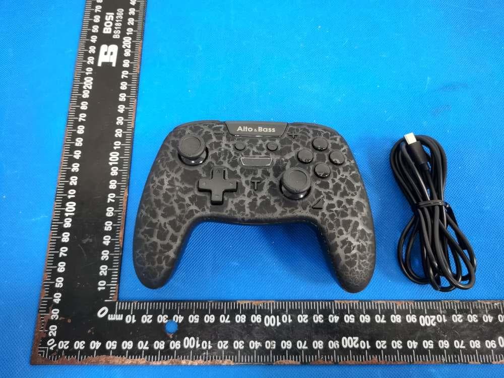
Click to zoom
Application Details
- Equipment Class
- DXX - Part 15 Low Power Communication Device Transmitter
- Date of Grant
- Dec 06, 2022
- Application Purpose
- Original Equipment
- Date of Application
- Dec 06, 2022
- Equipment Note
- Gamepad
- Frequency Range
- 2402.00000000 - 2480.00000000
- Country
- China
Documents & Files
Document Text
Text extracted from the exhibit documents filed with the FCC. Open a document above to read the original.
Users Manual
Questions, problems, missing parts? Before returning to the store, please contact our Customer Service [email protected] THANK YOU We appreciate the trust and confidence you have placed in Alto & Bass through the purchase of our product. We strive to continually create quality products designed to enhance your home. Visit us online to see our full line of products available for your home improvement needs. Thank you for choosing Alto & Bass! User Manual CE-GP002/CE-GP003/HY-9013 Switch / Switch Lite / Switch OLED / PC / PC360 / Android Alto & Product layout and Packing Contents User Manual *Package includes wireless gamepad*1, type-C charging cable*1,User Manual*1. The controller consists of several function buttons (D-PAD, A, B, X, Y, L1, R1, L2, R2, L3, R3, -, +, Turbo, Capture, Home) and two 3D analog sticks. Application Instruction Product Parameters 1.Wireless connection:BT5.0 2.Transmission distance:8m 3.Working current: 40mA 4.Charging voltage:5V 5.Charging current:400mA 6.Charging time:2~3H 7.Battery capacity:600mAHh Connect to Switch Connection Instruction 1.The controller supports Switch, Switch Lite and Switch OLED, while also compatible with PC, PC360, and Android. User can transfer between platforms by pressing different key combination. .The controller supports following functions: 6-axis, double motor vibration, channel instruction LED light, and decorative LED display. 3.The controller can receive signal up to 8 meters. -Wireless Connection: (First-time connection) 1.Press “Home” button to enter the main interface, choose: “Controller and Sensors” > “Change Grip/Order”; 2.Long press “Home” button for 2-3 seconds to power on the controller and start pairing. While pairing, the LED indicator lights 1 to 4 flash circularly. 3.If pairing succeeds, the console will distribute channel automatically and the corresponding indicator light will keep on. -Wired Communication: (First-time connection) 1.Make sure the Switch console has allowed controller to build wired communication in “Settings”: (“Settings” > “Controller and Sensors” > ”Pro Controller Wired Communication” > “On”; 2.Put the Switch console on the Switch Dock, use appendant Type-C cable to connect to the USB port on the dock, and then the controller will build communi cation with the console automatically. -Wake up & Reconnection: After building the first connection, the controller will be allowed to wake up from sleeping mode by pressing “Home” button for 1 second, and it will automatically reconnect to the console without pairing again. Press “A” button. 1.Turn on Bluetooth on Android device and search for the controller; 2.Press “B”+”Home” to power on the controller and enter pairing mode; 3.While the indicator light LED2 and LED3 are flashing circularly, find “Gamepad” on Bluetooth interface of the device, click it to start pairing. If pairing succeeds, the LED2 and LED3 will keep on. 4.The controller supports mouse function by pressing “L3”+”R3”. Screenshot, 6-axis and motor vibration are not supported on phone. 1.While power-off, connect the controller to the USB port on computer by Type-C cable; 2.When connection succeeds, it defaults to XINPUT mode; 3.Long press button combination (“+” and “-”) to switch between DINPUT mode and XINPUT mode: XINPUT mode: LED1 and LED2 on DINPUT mode: LED3 and LED3 on Connect to Android device Connect to PC Bluetooth Connection 1.It requires the computer to support Bluetooth function or with Bluetooth receiver; 2.Turn on the Bluetooth and choose “add a device” (“Settings > “Devices” > “Bluetooth and other devices” >“Add Bluetooth & other device”) 3.Press “R1”+“Home” to power on the controller and enter Bluetooth pairing status. While pairing, the indicator light LED1 and LED4 will flash. 5.Find “Xbox Wireless Controller” on computer, click it to pair. If pairing succeeds, the LED1 and LED4 will keep on. It supports HID device. PS: Screenshot and vibration adjustment function are not supported on computer or Steam; Press “Home” button for 1 second to power on the controller, it will automatically reconnect to the device paired last time. Controller Function Instruction Display LED adjustment (Press LED switch button ) Change the color: Red, yellow, light green, dark green, blue, and purple (6 colors) 1.After power on, the display light defaults to be breathing mode and the colors will circular automatically. If user presses the LED switch button while displaying one color, it will change to single-color breathing mode. Press the LED switch button again to cancel the setting and go back to several-color breathing circularly. 2.Switch on/off: double click the LED switch button; 3.Switch breathing light to keep-on status: (Short press) LED switch button + “X”; 4.Change the displayed light color: color cannot be changed when in breathing light mode; click the LED switch button to change the color when in light-keep-on mode; 5.Increase brightness: long press LED switch button + “up” in D-pad; 6.Decrease brightness: long press LED switch button + “down” in D-pad. Motor vibration Turbo function Four level strength can be adjusted: 100% > 60% (default) > 30% > 0% 1.Increase strength: long press “Turbo” button + “up” in D-pad; 2.Decrease strength: long press “Turbo” button + “down” in D-pad; Three grades can be adjusted: Manual > Automatic > Cancel Buttons can be set up turbo function: A, B, X, Y, L1, L2, R1, R2; -Manual Turbo: Press Turbo and any action button can set up Turbo function for that button. -Automatic Turbo: Repeat the previous operation (Turbo + action button) can set up automatic Turbo function for that button. -Cancel Turbo: Repeat the operation again (Turbo +action button) can cancel the Turbo function setup. -Remove Turbo: Long press “Turbo” button for 3 seconds and then press “-” button to remove all the Turbo function set up before. -Turbo speed adjustment: Three speed levels can be switched: 5 shot/second > 12 shot/second (default) > 20 shot/second 1.Speed up: Pr…
Text truncated - open the document above for the full version.
Cover Letter(s)
NANJING HUAHONG OUTDOOR EQUIPMENT CO.,LTD Agent Authorization Company: NANJING HUAHONG OUTDOOR EQUIPMENT CO.,LTD Address: Room 1607, No.49, North Yunnan Road, Gulou District, Nanjing Product Name: Gamepad Model Number(s): CE-GP002, CE-GP003, HY-9013 Product Description: Gamepad FCC ID: 2A9LP-CEGP002 We authorize MiCOM Labs Inc., 575 Boulder Court, Pleasanton, California 94566, USA, to act on our behalf on all matters concerning the certification of above named equipment. We declare that MiCOM Labs Inc. is allowed to forward all information related to the approval and certification of equipment to the regulatory agencies as required and to discuss any issues concerning the approval application. Any and all acts carried out by MiCOM Labs on our behalf shall have the same effect as acts of our own. Signature: Date: 2022-12-01 Name: Wanghuirong Title: Manager Company: NANJING HUAHONG OUTDOOR EQUIPMENT CO.,LTD
Cover Letter(s)
NANJING HUAHONG OUTDOOR EQUIPMENT CO.,LTD Model Difference Product Name: Gamepad Model Number: CE-GP002, CE-GP003, HY-9013 FCC Identifier: 2A9LP-CEGP002 All the models are the same circuit and RF module, except the model names. Regards Sincerely Client’s signature Client’s name / title : Wanghuirong / Manager Contact information / address: Room 1607, No.49, North Yunnan Road, Gulou District, Nanjing
Cover Letter(s)
NANJING HUAHONG OUTDOOR EQUIPMENT CO.,LTD Office of Engineering Technology Federal Communications Commission 7435 Oakland Mills Road Columbia, MD 21046 USA Date: 2022-12-01 Subject; Request for Confidentiality FCC ID: 2A9LP-CEGP002 To Whom It May Concern, Pursuant to the provisions of the Commission’s rules Title 47 Sections §0.457 and §0.459, we are requesting the Commission to withhold the following attachment(s) as confidential documents from public disclosure indefinitely. These documents contain detailed system and equipment descriptions and are considered as proprietary information in operation of the equipment. The public disclosure of these documents might be harmful to our company and would give competitors an unfair advantage in the market. Schematic Diagram Block Diagram Parts List Operational Description Tune-up Procedure It is our understanding that all measurement test reports, FCC ID label format and correspondence during the certification review process cannot be granted as confidential documents and this information will be available for public review once the grant of equipment authorization is issued. Sincerely, Signature: Name: Wanghuirong Title: Manager
ID Label/Location Info
Size:4*1.8cm M/N: CE-GP002 FCC ID: 2A9LP-CEGP002 Label location
Internal Photos
ANT
Test Report
Summary Antenna Specification ITEMANT SPEC Model Name2.4G ANT MAX. Gain 1.08dBi PolarizationHorizontal and Vertical Azimuth Beam Pattern Omni-directional Impedance50 Ohm Antenna Length38.20mm Manufacture NANJING HUAHONG OUTDOOR EQUIPMENT CO.,LTD ÏÚ 2 ‹ Œøº∑ø ̈∑±≤ Ω∏øÆøΩ ̈ªÆ∑≠ ̈∑Ω≠ ±∫ ø≤ ̈ª≤≤ø PHI 0° PHI90° THETA90 ° Frequency VNA (MHz) Gain (Peak) (dBi) 2400MHz0.0403503 2410MHz0.0886264 2420MHz0.267381 2430MHz0.193012 2440MHz0.26366 2450MHz0.0723139 2460MHz0.36895 2470MHz0.551525 2480MHz0.640702 2490MHz1.05232 2500MHz1.08443 Unit:dB
Test Report
Shenzhen DL Testing Technology Co., Ltd. Report No.: DL-20221129025E Test Report Tel: 400-688-3552 Web:www.dl-cert.com Email: [email protected] Page 1 of 34 FCC Part 15C Test Report FCC ID: 2A9LP-CEGP002 Applicant: NANJING HUAHONG OUTDOOR EQUIPMENT CO.,LTD Address: Room 1607, No.49, North Yunnan Road, Gulou District, Nanjing Manufacturer: NANJING HUAHONG OUTDOOR EQUIPMENT CO.,LTD Address: Room 1607, No.49, North Yunnan Road, Gulou District, Nanjing EUT: Gamepad Trade Mark: Alto&Bass Model Number: CE-GP002 CE-GP003, HY-9013 Date of Receipt: Nov. 22, 2022 Test Date: Nov. 22, 2022 - Nov. 29, 2022 Date of Report: Nov. 29, 2022 Prepared By: Shenzhen DL Testing Technology Co., Ltd. Address: 101-201, Building C, Shuanghuan, No.8, Baoqing Road, Baolong Industrial Zone, Baolong Street, Longgang District, Shenzhen, Guangdong, China Applicable Standards: FCC PART 15 C 15.249 ANSI C63.10:2013 Test Result: Pass Report Number: DL-20221129025E Prepared (Test Engineer): Pxing Huang Reviewer (Supervisor): Jack Bu Approved (Manager): Jade Yang This test report is based on a single evaluation of one sample of above mentioned products. It is not permitted to be duplicated in extracts without written approval of Shenzhen DL Testing Technology Co., Ltd. Shenzhen DL Testing Technology Co., Ltd. Report No.: DL-20221129025E Test Report Tel: 400-688-3552 Web:www.dl-cert.com Email: [email protected] Page 2 of 34 Table of Contents Page 1 . SUMMARY OF TEST RESULTS 4 1.1 MEASUREMENT UNCERTAINTY 4 2 . GENERAL INFORMATION 5 2.1 GENERAL DESCRIPTION OF EUT 5 2.2 DESCRIPTION OF TEST MODES 6 2.3 BLOCK DIGRAM SHOWING THE CONFIGURATION OF SYSTEM TESTED 7 2.4 DESCRIPTION OF SUPPORT UNITS(CONDUCTED MODE) 7 2.5 TABLE OF PARAMETERS OF TEST SOFTWARE SETTING 7 2.6 EQUIPMENTS LIST FOR ALL TEST ITEMS 8 3 . EMC EMISSION TEST 9 3.1 CONDUCTED EMISSION MEASUREMENT 9 3.1.1 POWER LINE CONDUCTED EMISSION LIMITS 9 3.1.2 TEST PROCEDURE 9 3.1.3 DEVIATION FROM TEST STANDARD 9 3.1.4 TEST SETUP 10 3.1.5 EUT OPERATING CONDITIONS 10 3.1.6 TEST RESULTS 10 3.2 RADIATED EMISSION MEASUREMENT 13 3.2.1 RADIATED EMISSION LIMITS 13 3.2.2 TEST PROCEDURE 14 3.2.3 DEVIATION FROM TEST STANDARD 14 3.2.4 TEST SETUP 14 3.2.5 EUT OPERATING CONDITIONS 15 3.2.6 TEST RESULTS (BETWEEN 9KHZ – 30 MHZ) 16 3.2.7 TEST RESULTS (BETWEEN 30MHZ – 1GHZ) 17 3.2.8 TEST RESULTS (1GHZ~25GHZ) 19 3.3 RADIATED BAND EMISSION MEASUREMENT 20 3.3.1 TEST REQUIREMENT: 20 3.3.2 TEST PROCEDURE 20 3.3.3 DEVIATION FROM TEST STANDARD 20 3.3.4 TEST SETUP 21 3.3.5 EUT OPERATING CONDITIONS 21 4 . BANDWIDTH TEST 23 4.1 APPLIED PROCEDURES / LIMIT 23 4.1.1 TEST PROCEDURE 23 4.1.2 DEVIATION FROM STANDARD 23 4.1.3 TEST SETUP 23 4.1.4 EUT OPERATION CONDITIONS 23 Shenzhen DL Testing Technology Co., Ltd. Report No.: DL-20221129025E Test Report Tel: 400-688-3552 Web:www.dl-cert.com Email: [email protected] Page 3 of 34 Table of Contents Page 4.1.5 TEST RESULTS 24 5 . ANTENNA REQUIREMENT 25 5.1 STANDARD REQUIREMENT 25 5.2 EUT ANTENNA 25 6 . TEST SEUUP PHOTO 26 7 . EUT PHOTO 28 Shenzhen DL Testing Technology Co., Ltd. Report No.: DL-20221129025E Test Report Tel: 400-688-3552 Web:www.dl-cert.com Email: [email protected] Page 4 of 34 1. SUMMARY OF TEST RESULTS Test procedures according to the technical standards: FCC Part15 (15.249) , Subpart C Standard Section Test Item Judgment Remark 15.207 Conducted Emission PASS 15.205(a), 15.209(a) 15.249(a), 15.249(c) Fundamental &Radiated Spurious Emission Measurement PASS 15.249(d) Band Edge Emission PASS 15.215(c) 20dB Bandwidth PASS 15.203 Antenna Requirement PASS NOTE: (1)” N/A” denotes test is not applicable in this Test Report 1.1 MEASUREMENT UNCERTAINTY The reported uncertainty of measurement y ± U, where expended uncertainty U is based on a standard uncertainty multiplied by a coverage factor of k=2,providing a level of confidence of approximately 95 %. No. Item Uncertainty 1 Conducted Emission Test ±2.56dB 2 RF power,conducted ±0.42dB 3 Spurious emissions,conducted ±2.76dB 4 All emissions,radiated(<1G) ±3.65dB 5 All emissions,radiated(>1G) ±4.89dB 6 Temperature ±0.5°C 7 Humidity ±2% Shenzhen DL Testing Technology Co., Ltd. Report No.: DL-20221129025E Test Report Tel: 400-688-3552 Web:www.dl-cert.com Email: [email protected] Page 5 of 34 2. GENERAL INFORMATION 2.1 GENERAL DESCRIPTION OF EUT Product Name: Gamepad Trademark Alto&Bass Model No.: CE-GP002 CE-GP003, HY-9013 Model Difference The product's different for model number. Operation Frequency: 2402~2480MHz Channel numbers: 40 Channels Channel separation: 2M Modulation technology: GFSK Antenna Type: Internal Antenna Antenna gain: 1.08dBi Power supply: DC 3.7V from battery DC 5V from charger Note: 1.For a more detailed features description, please refer to the manufacturer’s specifications or the User's Manual. 2.The EUT’s all information provided by client. Shenzhen DL Testing Technology Co., Ltd. Report No.: DL-20221129025E Test Report Tel: 400-688-3552 Web:www.dl-cert.com Email: [email protected] Page 6 of 34 3. Channel List Channel Frequency (MHz) Channel Frequency (MHz) Channel Frequency (MHz) 00 2402 14 2430 27 2456 01 2404 15 2432 28 2458 02 2406 16 2434 29 2460 03 2408 17 2436 30 2462 04 2410 18 2438 31 2464 05 2412 19 2440 32 2466 06 2414 20 2442 33 2468 07 2416 21 2444 34 2470 08 2418 22 2446 35 2472 09 2420 23 2448 36 2474 10 2422 24 2450 37 2476 11 2424 25 2452 38 2478 12 2426 26 2454 39 2480 13 2428 / / / / 2.2 DESCRIPTION OF TEST MODES Note: (1) The measurements are performed at the highest, middle, lowest available channels. (2) A new fully charged battery was used for testing during the test. To investigate the maximum EMI emission characteristics generates from EUT, the test system was pre-scanning tested base on the consideration of following EUT operation mode or test configuration mode which possible have effect on EMI emission level. Each of these EUT operation mode(s) or test configuration mode(s) mentioned above was evaluated respectively. Pretest Mode Description Mode 1 CH0…
Text truncated - open the document above for the full version.
Test Setup Photos
Radiated Measurement Photos Conducted Measurement Photos
Contact Information
Applicant
Wang huirong
Technical Contact
Test Firm
Shenzhen DL Testing Technology Co., Ltd.Jade Yang
[email protected]400-688-3552
Technical Specifications
| # | Rule Parts | Frequency Range | Power Output |
|---|---|---|---|
| 1 | 15C | 2.40 GHz - 2.48 GHz | - |