2A9NA-LD-M4Wireless charger
Ningbo Lede Computer Technology Co., Ltd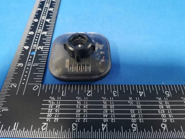
Click to zoom
Application Details
- Equipment Class
- DCD - Part 15 Low Power Transmitter Below 1705 kHz
- Date of Grant
- Dec 08, 2022
- Application Purpose
- Original Equipment
- Date of Application
- Dec 08, 2022
- Equipment Note
- Wireless charger
- Frequency Range
- 0.11000000 - 0.20500000
- Country
- China
Documents & Files
Document Text
Text extracted from the exhibit documents filed with the FCC. Open a document above to read the original.
Users Manual
Standard of execution:Q/NBLD001 - 2017 Place of origin:China Time of warranty:18 months Model:F-M4 Size:65.5*65.5*85.5mm Manufacturer:Ningbo Lede Computer Technology Co., LTD Address:12 Jiahe Road, Fengshan Street, Yuyao City, Ningbo City, Zhejiang Province Weight:71.4g 400-889-2826 www.ledetek.com LD-M4 Magnetic suction mobile phone vehicle support 1 Product components Precautions Limit of hazardous substances: Lead, copper, hexavalent chromium, polybrominated biphenyls and polybrominated diphenyl ethers content not more than 0.1% (mass fraction), The content of cadmium should not exceed 0.01% (mass fraction). Use a power adapter of 20W or higher Input:5V 3A or 9V 2A or 12V 2A(Max) Output:5 W/15W(Max) iPhone/Output:7.5W(Max) Installation Procedure Tighten the knob cap 3 Installation Complete 4 Place the knob cap into the ball tip 2 Insert the tip into the ball tip Instruction manual Suitable for mobile phones that support wireless charging and have magnetic absorption function FCC statement: This device complies with Part 15 of the FCC rules. Operation is subject to the following two conditions: 1) this device may not cause harmful interference, and 2) this device must accept any interference received, including interference that may cause undesired operation. Note: This equipment has been tested and found to comply with the limits for a Class B digital device, pursuant to part 15 of the FCC Rules. These limits are designed to provide reasonable protection against harmful interference in a residential installation. This equipment generates uses and can radiate radio frequency energy and, if not installed and used in accordance with the instructions, may cause harmful interference to radio communications. However, there is no guarantee that interference will not occur in particular installation. If this equipment does cause harmful interference to radio or television reception, which can be determined by turning the equipment off and on, the user is encouraged to try to correct the interference by one or more of the following measures: --Reorient or relocate the receiving antenna. --Increase the separation between the equipment and receiver. --Connect the equipment into an outlet on a circuit different from that to which the receiver is connected. --Consult the dealer or an experienced radio/TV technician for help. Changes or modifications not expressly approved by the party responsible for compliance could void the user’s authority to operate the equipment. Radiation Exposure Statement This device complies with FCC RF radiation exposure limits set forth for an uncontrolled environment. This transmitter must not be co-located or operating in conjunction with any other antenna or transmitter. During the operation of device a distance of 15 cm surrounding the device and 20 cm above the top surface of thedevice must be respected.
Cover Letter(s)
Sincerely, Name/Title: Yuman Lou/PM Company: Ningbo Lede Computer Technology Co., Ltd Address: NO.12 Jiahe Road, Fengshan Street, Yuyao City, Zhejiang Province China Phone: 13705848444 Fax: N/A E-Mail: [email protected]
External Photos
FCC ID: 2A9NA-LD-M4 External Photos of the EUT Photo 1 Photo 2 Photo 3 FCC ID: 2A9NA-LD-M4 Photo 4 Photo 5 Photo 6
ID Label/Location Info
Label and Location Size: L: 2.0cm*W: 1.5cm Label and Location Model: LD-M4 FCC ID : 2A9NA-LD-M4
Internal Photos
FCC ID: 2A9NA-LD-M4 Internal Photos of the EUT Photo 1 Photo 2 Photo 3 Loop coil antenna FCC ID: 2A9NA-LD-M4 Photo 4 Photo 5
RF Exposure Info
Page 1 of 5 RF Exposure Evaluation FCC ID: 2A9NA-LD-M4 1 Measuring Standard KDB 680106 D01 RF Exposure Wireless Charging Apps v03 2 Requirements According to the item 5 of KDB 680106 D01v03: Inductive wireless power transfer applications that meet all of the following requirements are excluded from submitting an RF exposure evaluation. (1) Power transfer frequency is less than 1MHz. (2) Output power from each primary coil is less than or equal to 15 watts. (3) The system may consist of more than one source primary coils, charging one or more clients. If more than one primary coil is present, the coil pairs may be powered on at the same time. (4) Client device is placed directly in contact with the transmitter. (5) Mobile exposure conditions only (portable exposure conditions are not covered by this exclusion). (6) The aggregate H-field strengths anywhere at or beyond 15 cm surrounding the device,and 20 cm away from the surface from all coils that by design can simultaneously transmit,and while those coils are simultaneously energized, are demonstrated to be less than 50% of the applicable MPE limit. Limits The criteria listed in the following table shall be used to evaluate the environment impact of human exposure to radio frequency (RF) radiation as specified in 1.1307(b) Limits for Maximum Permissible Exposure (MPE) Page 2 of 5 3 Test Setup 4 Test Procedure 1) The RF exposure test was performed in anechoic chamber. 2) The measurement probe was placed at test distance (15 cm from all sides and 20 cm from the top) which is between the edge of the charger and the geometric center of probe. 3) The highest emission level was recorded and compared with limit as soon as measurement of each points (A, B, C, D, E) were completed. 4) The EUT was measured according to the dictates of KDB 680106 D01v03. Remark:The EUT’s test position A, B, C, D and E is valid for the E and H field measurements. 5 Equipment Approval Considerations The EUT does comply with KDB 680106 D01 as follow table. Requirements of KDB 680106 D01 Yes / No Description Power transfer frequency is less than 1 MHz Yes The device operate in the frequency range 110KHz~205KHz Output power from each primary coil is less than 15 watts Yes The maximum output power for each primary coil is 15W. The system may consist of more than one source primary coils, charging one or more clients. If more than one primary coil is present, the coil pairs may be powered on at the same time. Yes The transfer system includes only one primary coils. Client device is placed directly in contact with the transmitter. Yes Client device is placed directly in contact with the transmitter. Mobile exposure conditions only (portable exposure conditions are not covered by this exclusion). Yes Mobile exposure conditions only The aggregate H-field strengths anywhere at or beyond 15 cm surrounding the device, and 20 cm away from the surface from all coils that by design can simultaneously transmit, Yes The EUT H-field strengths at 15 cm surrounding the device and 20 cm above the top surface from all simultaneous transmitting coils are demonstrated to be less than 50% of Page 3 of 5 and while those coils are simultaneously energized, are demonstrated to be less than 50% of the applicable MPE limit. the MPE limit. 6 Description of the test mode Equipment under test was operated during the measurement under the following conditions: Charging and communication mode Test Modes: Mode 1 AC/DC Adapter (5V/3.0A) + EUT + Full Load Pre-tested Mode 2 AC/DC Adapter (5V/3.0A) + EUT + Half Load Pre-tested Mode 3 AC/DC Adapter (5V/3.0A) + EUT + Empty Load Pre-tested Mode 4 AC/DC Adapter (9V/2.0A) + EUT + Full Load Pre-tested Mode 5 AC/DC Adapter (9V/2.0A) + EUT + Half Load Pre-tested Mode 6 AC/DC Adapter (9V/2.0A) + EUT + Empty Load Pre-tested Mode 4 AC/DC Adapter (12V/2.0A) + EUT + Full Load Record Mode 5 AC/DC Adapter (12V/2.0A) + EUT + Half Load Record Mode 6 AC/DC Adapter (12V/2.0A) + EUT + Empty Load Record Note: All test modes were pre-tested, but we only recorded the worst case in this report. 7 Description of Support Units Follow auxiliary equipment(s) test with EUT that provided by the manufacturer or laboratory is listed as follow: Description Manufacturer Model Technical Parameters Certificate Provided by Adapter / EP-TA20CBC / SDOC Lab. Page 4 of 5 8 Test Instruments list Test Equipment Manufacturer Model No. SN. Cal.Date (mm-dd-yy) Cal.Due date (mm-dd-yy) Exposure Level Tester Narda ELT-400 N-0231 June 27 2022 June 26 2023 Magnetic field probe 100cm 2 Narda ELT probe 100cm 2 M0675 June 27 2022 June 26 2023 9 Test Result H-Field Strength at 15 cm from the edges surrounding the EUT and 15cm from the top surface of the EUT Chargin g Battery Level Unit Frequency Range (MHz) Measured E-Field Strength Values (A/m) FCC H-Field Strength 50% Limits (A/m) FCC H-Field Strength Limits (A/m) Test Position A Test Position B Test Position C Test Position D Test Position E 1% uT 0.125 0.415 0.386 0.403 0.401 0.398 -- -- 1% A/m 0.125 0.332 0.309 0.322 0.321 0.318 0.815 1.63 50% uT 0.125 0.280 0.276 0.290 0.281 0.286 -- -- 50% A/m 0.125 0.224 0.221 0.232 0.225 0.229 0.815 1.63 99% uT 0.125 0.151 0.159 0.158 0.161 0.164 -- -- 99% A/m 0.125 0.121 0.127 0.126 0.129 0.131 0.815 1.63 E-Field Strength at 15 cm from the edges surrounding the EUT and 15cm from the top surface of the EUT Chargin g Battery Level Unit Frequency Range (MHz) Measured E-Field Strength Values (V/m) FCC E-Field Strength 50% Limits (V/m) FCC E-Field Strength Limits (V/m) Test Position A Test Position B Test Position C Test Position D Test Position E 1% V/m 0.125 125.164 116.493 121.394 121.017 119.886 307.0 614.0 50% V/m 0.125 84.448 83.317 87.464 84.825 86.333 307.0 614.0 99% V/m 0.125 45.617 47.879 47.502 48.633 49.387 307.0 614.0 Note: V/m= A/m *377 Page 5 of 5 H-Field Strength at 20cm from the top surface of the EUT Charging Battery Level Unit Frequency Range (MHz) Measured E-Field Strength Values (A/m) FCC H-Field Str…
Text truncated - open the document above for the full version.
Test Report
1. Antenna Description: Antenna type Loop coil antenna Model LD-M4 Frequency range From 110KHz~205KHz Manufacturer Ningbo Lede Computer Technology Co., Ltd 2. Antenna Photo: Length:41.10mm diameter:10.27mm
Test Report
Shenzhen CTA Testing Technology Co., Ltd. Room 106, Building 1, Yibaolai Industrial Park, Qiaotou Community, Fuhai Street, Bao’an District, Shenzhen, China Shenzhen CTA Testing Technology Co., Ltd. Room 106, Building 1, Yibaolai Industrial Park, Qiaotou Community, Fuhai Street, Bao’an District, Shenzhen, China Tel:+86-755 2322 5875 E-mail:[email protected] Web:http://www.cta-test.cn FCC PART 15 SUBPART C TEST REPORT Report Reference No. ..................... : FCC ID............................................. : CTA22112901401 2A9NA-LD-M4 Compiled by ( position+printed name+signature) . : File administrators Zoey Cao Supervised by ( position+printed name+signature) . : Project Engineer Amy Wen Approved by ( position+printed name+signature) . : RF Manager Eric Wang Date of issue .................................... : Dec. 06, 2022 Testing Laboratory Name .............. : Shenzhen CTA Testing Technology Co., Ltd. Address............................................ : Room 106, Building 1, Yibaolai Industrial Park, Qiaotou Community, Fuhai Street, Bao‘an District, Shenzhen, China Applicant’s name ............................ : Ningbo Lede Computer Technology Co., Ltd Address............................................ : NO.12 Jiahe Road, Fengshan Street, Yuyao City, Zhejiang Province, China Test specification ........................... : Standard ........................................... : FCC Rules and Regulations Part 15 Subpart C (Section 15.209), ANSI C63.10: 2013 Shenzhen CTA Testing Technology Co., Ltd. All rights reserved. This publication may be reproduced in whole or in part for non-commercial purpses as long as the Shenzhen CTA Testing Technology Co., Ltd. is acknowledged as copyright owner and source of the material. Shenzhen CTA Testing Technology Co., Ltd. takes no responsibility for and will not assume liability for damages resulting from the reader's interpretation of the reproduced material due to its placement and context. Test item description ..................... : Wireless charger Trade Mark ....................................... : N/A Manufacturer .................................... : Ningbo Lede Computer Technology Co., Ltd Model/Type reference ...................... : LD-M4 Listed Models .................................. : N/A Modulation Type ............................... : ASK Operation Frequency ........................ : From 110KHz~205KHz Rating ............................................... : Input: 5V/3A, 9V/2A, 12V2A Output: 7.5W/15W(Max) iPhone/Output:7.5W Result ............................................... : PASS Report No.: CTA22112901401 Page 2 of 22 Shenzhen CTA Testing Technology Co., Ltd. Room 106, Building 1, Yibaolai Industrial Park, Qiaotou Community, Fuhai Street, Bao’an District, Shenzhen, China Tel:+86-755 2322 5875 E-mail:[email protected] Web:http://www.cta-test.cn T E S T R E P O R T Equipment under Test : Wireless charger Model /Type : LD-M4 Listed Models : N/A Applicant : Ningbo Lede Computer Technology Co., Ltd Address : NO.12 Jiahe Road, Fengshan Street, Yuyao City, Zhejiang Province, China Manufacturer : Ningbo Lede Computer Technology Co., Ltd Address : NO.12 Jiahe Road, Fengshan Street, Yuyao City, Zhejiang Province, China Test Result: PASS The test report merely corresponds to the test sample. It is not permitted to copy extracts of these test result without the written permission of the test laboratory. Report No.: CTA22112901401 Page 3 of 22 Shenzhen CTA Testing Technology Co., Ltd. Room 106, Building 1, Yibaolai Industrial Park, Qiaotou Community, Fuhai Street, Bao’an District, Shenzhen, China Tel:+86-755 2322 5875 E-mail:[email protected] Web:http://www.cta-test.cn Contents 1 T E S T S T A N D A R D S ................................................................. 4 2 S U M M A R Y ............................................................................ 5 2.1 General Remarks 5 2.2 Product Description 5 2.3 Description of the test mode 5 2.4 Special Accessories 5 2.5 Modifications 5 3 T E S T E N V I R O N M E N T .............................................................. 6 3.1 Address of the test laboratory 6 3.2 Test Facility 6 3.3 Environmental conditions 6 3.4 Summary of measurement results 7 3.5 Statement of the measurement uncertainty 7 3.6 Equipments Used during the Test 8 4 T E S T C O N D I T I O N S A N D R E S U L T S ............................................. 9 4.1 AC Power Conducted Emission 9 4.2 Radiated Emission 12 4.3 The 20dB bandwidth 16 4.4 Antenna Requirement 17 5 T E S T S E T U P PH O TOS OF T H E E U T ......................................... 18 6 PH O T O S O F T H E E U T ........................................................... 19 Report No.: CTA22112901401 Page 4 of 22 Shenzhen CTA Testing Technology Co., Ltd. Room 106, Building 1, Yibaolai Industrial Park, Qiaotou Community, Fuhai Street, Bao’an District, Shenzhen, China Tel:+86-755 2322 5875 E-mail:[email protected] Web:http://www.cta-test.cn 1 T E S T S T A N D A R D S The tests were performed according to following standards: FCC Rules and Regulations Part 15 Subpart C (Section 15.207): Conducted limits. FCC Rules and Regulations Part 15 Subpart C (Section 15.209): Radiated emission limits; general requirements. ANSI C63.10: 2013: American National Standard for Testing Unlicensed Wireless Devices Report No.: CTA22112901401 Page 5 of 22 Shenzhen CTA Testing Technology Co., Ltd. Room 106, Building 1, Yibaolai Industrial Park, Qiaotou Community, Fuhai Street, Bao’an District, Shenzhen, China Tel:+86-755 2322 5875 E-mail:[email protected] Web:http://www.cta-test.cn 2 S U M M A R Y 2.1 General Remarks Date of receipt of test sample : Nov. 29, 2022 Testing commenced on : Nov. 29, 2022 Testing concluded on : Dec. 06, 2022 2.2 Product Description Product Name: Wireless charger Model/Type reference: LD-M4 Hardware version: V1.0 Software version: V1.0 Test samples ID: CTA221129014-1# (Engineer sample), CTA221129014-2# (Normal sample) Power supp…
Text truncated - open the document above for the full version.
Test Setup Photos
FCC ID: 2A9NA-LD-M4 Test Setup Photos of the EUT
Contact Information
Applicant
Yuman Lou
Test Firm
SHENZHEN CTA TESTING TECHNOLOGY CO., LTD.Eric Wang
[email protected]+86 755 2322 5875
Technical Specifications
| # | Rule Parts | Frequency Range | Power Output |
|---|---|---|---|
| 1 | 15C | 0.11 MHz - 0.205 MHz | - |