2A9PK-P2000Auto Video adapter kit
MR12VOLT DIGITAL LIMITED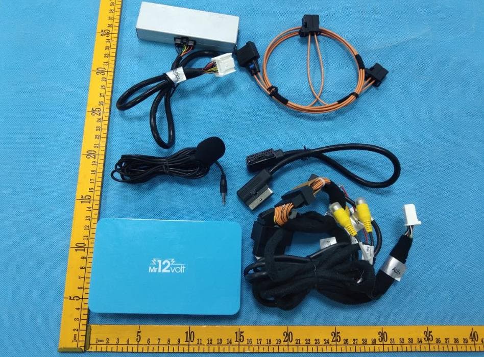
Click to zoom
Application Details
- Equipment Class
- DTS - Digital Transmission System
- Date of Grant
- Dec 14, 2022
- Application Purpose
- Original Equipment
- Date of Application
- Dec 14, 2022
- Equipment Note
- Auto Video adapter kit
- Frequency Range
- 2412.00000000 - 2462.00000000
- Company
- MR12VOLT DIGITAL LIMITED
- Country
- China
Documents & Files
Document Text
Text extracted from the exhibit documents filed with the FCC. Open a document above to read the original.
Users Manual
User Manual Common problem 1、How to connect the device with the original car? Connect the device to the USB / type-c socket of the original car through the data cable. The device's running light turns on and enters the blue breathing state to indicate successful startup. When the original car display enters the device interface, it indicates that the connection with the original car is successful. Note: The USB interface of the original car is generally located in the front storage compartment or in the armrest box. Android phones: Please search for happycast in the app store and download the app, connect the phone to the same Wi-Fi as the current device, open the app and start casting 5、How to use the U disk media of the device? Insert the U disk into the USB interface of the device, and then open the [U disk] function in the device system interface, click to enter to view the audio and video files in the U disk (supported formats: music support WAV, AAC, WMA, AMR, MP3, FLAC format; video temporarily supports MP4, AVI format), click to play. 6 、 After returning to the original car system, how to switch back to the equipment system? Find the USB device management function in the original car system menu (or display as "Apple CarPlay" / "mobile phone interconnection"), you can enter the device system interface 7 、 How to return to the original car from the system interface? On the homepage of the device, click the Home button, and it will prompt "Whether to return to the original car system", click OK to switch back to the original car system interface. Find the return to the original car icon in the device interface, click to switch back to the original car system interface. 8、How to upgrade? You can upgrade through the U disk, copy the upgraded version to the U disk, then insert the U disk into the USB interface of the device, and the upgrade will be automatically detected 9 、 After clicking to start the upgrade immediately, how to judge the upgrade is complete? The upgrade uses a silent upgrade method. No screen will be displayed during the upgrade process. The upgrade will take 3 to 5 minutes. When you click to upgrade immediately, please do not 2、How to connect to a wireless network? Open the hotspot of the mobile phone or other network devices that can be shared, click the [Control-WLAN] on the central control screen to enter the network list interface, select the network and enter the password Note: The non-touch central control screen needs to change the hotspot password of the mobile phone or other shareable network device to 12345678. Enter the network list interface through the original car touchpad or knob, select the hotspot connection unplug the device or turn o ff the vehicle to avoid damage. The upgrade will be successful. After that, it will automatically enter the AI box interface, indicating that the upgrade has been completed. 10、What should I do if I unplug the device during the upgrade? Please try don't interrupt the upgrade during the upgrade process. If the incorrect operation causes the upgrade to be unsuccessful and cannot enter the equipment system normally, please contact the dealer. Packing list 3、How to use the device's Bluetooth phone? Find and open the [Bluetooth phone] in the AI box system interface to enter the Bluetooth connection page. Please find the corresponding device name in the Bluetooth settings of the phone to select and connect. After the connection is successful, you can use the function of making / receiving calls 4 、 How to use the device's mobile phone to cast screen? Open [PhoneCast] in the system interface to enter the tutorial page. Please keep the device and mobile phone in the same network environment. IPhone: Open the [Control Center] on the phone, click [Screen Mirror], find and click the name of the device to cast the screen, and the screen will be successfully screened. Host1 set Instruction Manual 1 piece Data cable1 piece Certificate of conformity 1 piece Separate GPS kit Optional Warning: Changes or modifications to this unit not expressly approved by the party responsible for compliance could void the user’s authority to operate the equipment. NOTE: This device complies with part 15 of the FCC Rules. Operation is subject to the following two conditions: (1) This device may not cause harmful interference, and (2) this device must accept any interference received, including interference that may cause undesired operation. FCC Statement: This equipment has been tested and found to comply with the limits for a Class B digital device, pursuant to part 15 of the FCC Rules. These limits are designed to provide reasonable protection against harmful interference in a residential installation. This equipment generates, uses and can radiate radio frequency energy and, if not installed and used in accordance with the instructions, may cause harmful interference to radio communications. However, there is no guarantee that interference will not occur in a particular installation. If this equipment does cause harmful interference to radio or television reception, which can be determined by turning the equipment off and on, the user is encouraged to try to correct the interference by one or more of the following measures: —Reorient or relocate the receiving antenna. —Increase the separation between the equipment and receiver. —Connect the equipment into an outlet on a circuit different from that to which the receiver is connected. —Consult the dealer or an experienced radio/TV technician for help. The equipment complies with FCC Radiation exposure limit set forth for uncontrolled environment. This equipment should be installed and operated with minimum distance 20cm between the radiator and your body.
Cover Letter(s)
MR12VOLT DIGITAL LIMITED Agent Authorization Company: MR12VOLT DIGITAL LIMITED Address: RM D FLAT 101,1/F INT'L PLAZA 20 SHEUNG YUET RD KOWLOON BAY KLN HONGKONG Product Name: Auto Video adapter kit Model Number(s): 2G26M0, P2000 Product Description: Auto Video adapter kit We authorize MiCOM Labs Inc., 575 Boulder Court, Pleasanton, California 94566, USA, to act on our behalf on all matters concerning the certification of above named equipment. We declare that MiCOM Labs Inc. is allowed to forward all information related to the approval and certification of equipment to the regulatory agencies as required and to discuss any issues concerning the approval application. Any and all acts carried out by MiCOM Labs on our behalf shall have the same effect as acts of our own. Signature: Date: Dec. 08, 2022 Name: Lin Ye Title: manager Company: MR12VOLT DIGITAL LIMITED
Cover Letter(s)
MR12VOLT DIGITAL LIMITED Date: Dec. 08, 2022 Office of Engineering Technology Federal Communications Commission 7435 Oakland Mills Road Columbia, MD 21046 USA Subject; Request for Confidentiality FCC ID: 2A9PK-P2000 To Whom It May Concern, Pursuant to the provisions of the Commission’s rules Title 47 Sections §0.457 and §0.459, we are requesting the Commission to withhold the following attachment(s) as confidential documents from public disclosure indefinitely. These documents contain detailed system and equipment descriptions and are considered as proprietary information in operation of the equipment. The public disclosure of these documents might be harmful to our company and would give competitors an unfair advantage in the market. In additional to above mentioned documents, in order to comply with the marketing regulations in Title 47 CFR §2.803 and the importation rules in Title 47 CFR §2.1204, while ensuring that business sensitive information remains confidential until the actual marketing of newly authorized devices, we request Short Term Confidentiality of the following attachment(s); External Photos Test Setup Photos Internal Photos User Manual For 45 days, pursuant to Public Notice DA 04-1705. OR For 180 days pursuant to KDB 726920 D01. It is our understanding that all measurement test reports, FCC ID label format and correspondence during the certification review process cannot be granted as confidential documents and this information will be available for public review once the grant of equipment authorization is issued. Sincerely, Signature: Name:Lin Ye Title:manager Schematic Diagram Block Diagram Parts List Operational Description Tune-up Procedure FCC Software Security Requirements for UNII devices
Cover Letter(s)
Project No.: ZKT-221114L8448-01 FCC ID: 2A9PK-P2000 MR12VOLT DIGITAL LIMITED Model Confirmation Letter We, (MR12VOLT DIGITAL LIMITED) certify the product: Auto Video adapter kit, models: 2G26M0, P2000 Their electrical circuit design, layout, components used and internal wiring are identical, Only the name will be different . Signiture: Grantee Contact: Lin Ye Company Name: MR12VOLT DIGITAL LIMITED Date: 2022-12-08
External Photos
Project No.: ZKT-221114L8448-01 FCC ID: 2A9PK-P2000 External photos Project No.: ZKT-221114L8448-01 FCC ID: 2A9PK-P2000 Project No.: ZKT-221114L8448-01 FCC ID: 2A9PK-P2000
ID Label/Location Info
Project No.: ZKT-221114L8448-01 FCC ID: 2A9PK-P2000 Label place SIZE: 70*50mm Auto Video adapter kit 1 2 3 4 5 A6/A8(a) OFF OFF OFF OFF OFF A6/A8(b) OFF OFF OFF ON OFF Q7(a) ON OFF OFF OFF OFF Q7(b) ON OFF OFF ON OFF Model Serials: P2000 FCC ID: 2A9PK-P2000 2022-03 MPN: 2G26MD
Internal Photos
Project No.: ZKT-221114L8448-01 FCC ID: 2A9PK-P2000 Internal photos ANT Project No.: ZKT-221114L8448-01 FCC ID: 2A9PK-P2000 Project No.: ZKT-221114L8448-01 FCC ID: 2A9PK-P2000
Test Report
Project No.: ZKT-221114L8448-01 Page 1 of 68 FCC TEST REPORT FCC ID: 2A9PK-P2000 Report Number. .............................. : ZKT-221114L8448-01 Date of Test ...................................... : Oct. 17, 2022 -- Nov. 25, 2022 Date of issue .................................... : Nov. 25, 2022 Total number of pages ..................... : 68 Test Result ....................................... : PASS Testing Laboratory. ........................ : Shenzhen ZKT Technology Co., Ltd. Address .......................................... : 1/F, No. 101, Building B, No. 6, Tangwei Community Industrial Avenue, Fuhai Street, Bao'an District, Shenzhen, China Applicant's name ......................... : MR12VOLT DIGITAL LIMITED Address .......................................... : RM D FLAT 101,1/F INT'L PLAZA 20 SHEUNG YUET RD KOWLOON BAY KLN HONGKONG Manufacturer's name ................... : MR12VOLT DIGITAL LIMITED Address .......................................... : RM D FLAT 101,1/F INT'L PLAZA 20 SHEUNG YUET RD KOWLOON BAY KLN HONGKONG Test specification: Standard .......................................... : FCC CFR Title 47 Part 15 Subpart C Section 15.247 ANSI C63.10:2013 Test procedure ................................. : KDB558074 D0115.247 Meas Guidance v 05r02 Non-standard test method ............. : N/A Test Report Form No. .................... : TRF-EL-110_V0 Test Report Form(s) Originator .... : ZKT Testing Master TRF .................................... : Dated: 2020-01-06 This device described above has been tested by ZKT, and the test results show that the equipment under test (EUT) is in compliance with the FCC requirements. And it is applicable only to the tested sample identified in the report. This report shall not be reproduced except in full, without the written approval of ZKT, this document may be altered or revised by ZKT, personal only, and shall be noted in the revision of the document. Product name ................................. : Auto Video adapter kit Trademark ...................................... : N/A Model/Type reference ...................... : 2G26M0, P2000 Ratings ............................................. : DC12V 500mA from car-battery Project No.: ZKT-221114L8448-01 Page 2 of 68 Testing procedure and testing location: Testing Laboratory ................................... : Shenzhen ZKT Technology Co., Ltd. Address ...................................................... : 1/F, No. 101, Building B, No. 6, Tangwei Community Industrial Avenue, Fuhai Street, Bao'an District, Shenzhen, China Alen He Tested by (name + signature) .................... : Joe Liu Reviewer (name + signature) ..................... : Lake Xie Approved (name + signature) .................... : Project No.: ZKT-221114L8448-01 Page 3 of 68 Table of Contents Page 1. VERSION 5 2. SUMMARY OF TEST RESULTS 6 2.1 TEST FACILITY 6 2.2 MEASUREMENT UNCERTAINTY 6 3. GENERAL INFORMATION 7 3.1 GENERAL DESCRIPTION OF EUT 7 3.2 DESCRIPTION OF TEST MODES 8 3.3 BLOCK DIGRAM SHOWING THE CONFIGURATION OF SYSTEM TESTED 9 3.4 DESCRIPTION OF SUPPORT UNITS(CONDUCTED MODE) 9 3.5EQUIPMENTS LIST FOR ALL TEST ITEMS 11 4. EMC EMISSION TEST 12 4.1 CONDUCTED EMISSION MEASUREMENT 12 4.1.1 POWER LINE CONDUCTED EMISSION LIMITS 12 4.1.2 TEST PROCEDURE 12 4.1.3 DEVIATION FROM TEST STANDARD 12 4.1.4 TEST SETUP 13 4.1.5 EUT OPERATING CONDITIONS 13 4.1.6 TEST RESULT 13 4.2 RADIATED EMISSION MEASUREMENT 14 4.2.1 RADIATED EMISSION LIMITS 14 4.2.2 TEST PROCEDURE 14 4.2.3 DEVIATION FROM TEST STANDARD 15 4.2.4 TEST SETUP 15 4.2.5 EUT OPERATING CONDITIONS 16 4.2.6 TEST RESULTS 16 5.RADIATED BAND EMISSIONMEASUREMENT 23 5.1 TEST REQUIREMENT: 23 5.2 TEST PROCEDURE 23 5.3 DEVIATION FROM TEST STANDARD 23 5.4 TEST SETUP 24 5.5 EUT OPERATING CONDITIONS 24 5.6 TEST RESULT 25 6.POWER SPECTRAL DENSITY TEST 27 6.1 APPLIED PROCEDURES / LIMIT 27 6.2 TEST PROCEDURE 27 6.3 DEVIATION FROM STANDARD 27 6.4 TEST SETUP 27 6.5 EUT OPERATION CONDITIONS 27 Project No.: ZKT-221114L8448-01 Page 4 of 68 6.6 TEST RESULT 27 7. CHANNEL BANDWIDTH 28 7.1 APPLIED PROCEDURES / LIMIT 28 7.2 TEST PROCEDURE 28 7.3 DEVIATION FROM STANDARD 28 7.4 TEST SETUP 28 7.5 EUT OPERATION CONDITIONS 28 7.6 TEST RESULT 28 8. OUTPUT POWER TEST 29 8.1 APPLIED PROCEDURES/LIMIT 29 8.2 TEST PROCEDURE 29 8.3 DEVIATION FROM STANDARD 29 8.4 TEST SETUP 29 8.5 EUT OPERATION CONDITIONS 29 8.6 TEST RESULT 29 9. CONDUCTED BAND EDGE AND SPURIOUS EMISSION 30 9.1 APPLICABLE STANDARD 30 9.2 TEST PROCEDURE 30 9.3 DEVIATION FROM STANDARD 30 9.4 TEST SETUP 30 9.5 EUT OPERATION CONDITIONS 30 9.6 TEST RESULTS 30 10. ANTENNA REQUIREMENT 31 11.1. -6DB BANDWIDTH 32 11.2. BANDEDGE 39 11.3. MAX. OUTPUT POWER 43 11.4. POWER SPECTRAL DENSITY 44 11.5. SPURIOUS EMISSION 50 12. TEST SETUP PHOTO 62 13. EUT CONSTRUCTIONAL DETAILS 63 Project No.: ZKT-221114L8448-01 Page 5 of 68 1. VERSION Report No. Version Description Approved ZKT-221114L8448-01 Rev.01 Initial issue of report Nov. 25, 2022 Project No.: ZKT-221114L8448-01 Page 6 of 68 2. SUMMARY OF TEST RESULTS Test procedures according to the technical standards: FCC Part15 (15.247) , Subpart C Standard Section Test Item Result Remark FCC part 15.203/15.247 (c) Antenna requirement PASS FCC part 15.207 AC Power Line Conducted Emission N/A FCC part 15.247 (b)(3) Conducted Peak Output Power PASS FCC part 15.247 (a)(2) Channel Bandwidth& 99% OCB PASS FCC part 15.247 (e) Power Spectral Density PASS FCC part 15.247(d) Band Edge PASS FCC part 15.205/15.209 Spurious Emission PASS NOTE: (1)” N/A” denotes test is not applicable in this Test Report 2.1 TEST FACILITY Shenzhen ZKT Technology Co., Ltd. Add. : 1/F, No. 101, Building B, No. 6, Tangwei Community Industrial Avenue, Fuhai Street, Bao'an District, Shenzhen, China FCC Test Firm Registration Number: 692225 Designation Number: CN1299 IC Registered No.: 27033 2.2 MEASUREMENT UNCERTAINTY The reported uncertainty of measurement y ± U, where expended uncertainty U is based on a standard uncertainty multiplied by a cover…
Text truncated - open the document above for the full version.
Test Report
List of recognition items 内容 页数 页码 NO. ( Number ( Page ( Contents ) ofPage ) Code ) 1 承认书封面(Spec Cover) 11 2 承认书项目表(Spec Item) 12 3 工程成品图(Drawing) 13 4 电性测试报告(Test Reports) 14 5 S参数测试(S Parameter) 15 6 增益测试 (Gain Test) 16 7 8 9 10 --- 11--- 12 --- Tel:15818375487 Dongguan Subo Electronics Co., Ltd. DESCRIPTIONSIGNDATEAPPROVER D C B YD 2015-11-06 SCALE: 1/1 UNITS: mm REVISION: A APPROVED BY Tolerance D C A E 7 6 5 4 32 1 D C B A E 7 5 6 4 3 1 2 TITLE: 2.4GHz 5GHz 5.8GHz Antenna PART NO.:WP9514-113B-120LX-IPEX DWG NAME: NB0200-113B-120LX-IPEX.DWG 4 32 1 C B A B CHECKED BYDESIDNED BY 8 8 ±3°X° X.X ±0.20 X.XX ±0.10 PCB 95*13.5*T0.6mm SHOWA-O.D. 1.13mm Black Mini Connector Part Number Name NB0200 PCB R-CB-113B Coaxial Cable Connector CI-113 1 No. 2 3 1 1 Q'ty 1 Material leon 2015-11-06 jeff 2015-11-06 Dongguan Subo Electronics Co., Ltd. 电性测试报告 TestReports Impedance500hmNominal ReturnLoss-10dBMax RadiationOmni-directional CableLoss4.9dB/mMax@5000MHz PolarizationLinear,Vertical AdmittedPower1W ConnectorIPEX PhysicalProperties AntennaMaterialPCB CableTypeO.D.1.8mm//150mm OperatingTemp. -10~+60 ̊C StorageTemp.-10~+70 ̊C SamplePhoto A.ElectricalCharacteristics Frequency 2400~2500MHz 4900~5900MHz S.W.R.<=2 Tel:15818375487 S参数测试 SParameterTest AgilentE5071C Tel:15818375487 增益测试 GainTest Antenna Radiation Pattern VS Gain 0 Tel:15818375487
Test Setup Photos
Project No.: ZKT-221114L8448-01 FCC ID: 2A9PK-P2000 Spurious Emission
Contact Information
Applicant
lin Ye
Technical Contact
Test Firm
Shenzhen ZKT Technology Co., Ltd.Lake Xie
[email protected]0086-13620010775
Technical Specifications
| # | Rule Parts | Frequency Range | Power Output |
|---|---|---|---|
| 1 | 15C | 2.41 GHz - 2.46 GHz | 40.30 mW |
Other Applications from MR12VOLT DIGITAL LIMITED
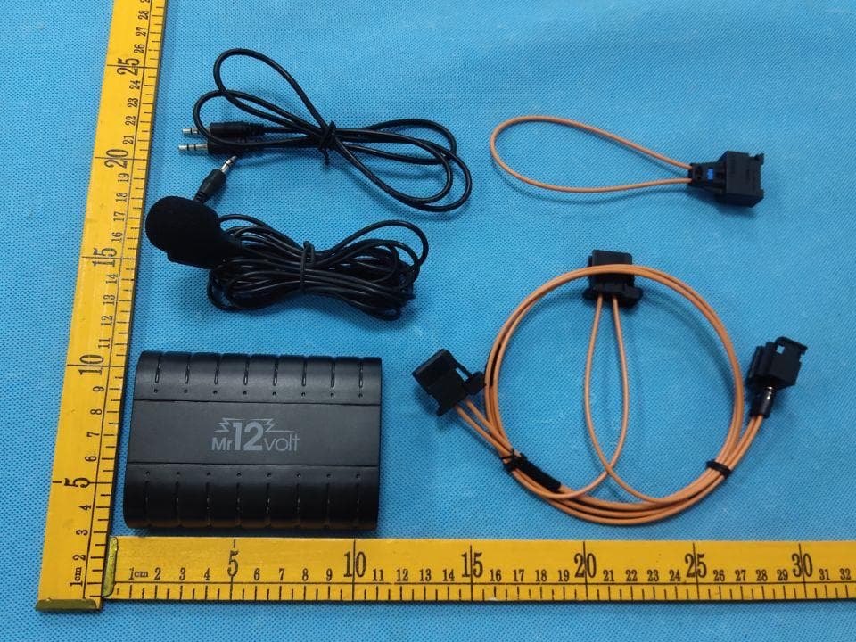
2A9PK-P600
Dec 13, 2022Car Radio MP3 Bluetooth adapter with Fiber Optic output
Equipment Class
DSS - Part 15 Spread Spectrum Transmitter