2A9TV-STFP2KHK1ROPureflo
DS Services of America, Inc. dba Primo Water North America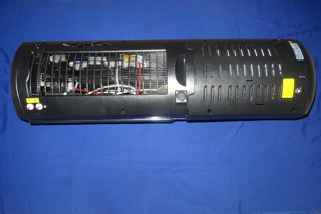
Click to zoom
Application Details
- Equipment Class
- PCB - PCS Licensed Transmitter
- Date of Grant
- May 07, 2023
- Application Purpose
- Original Equipment
- Date of Application
- May 07, 2023
- Equipment Note
- Pureflo
- Frequency Range
- 700.50000000 - 713.50000000
- Country
- United States
Documents & Files
Document Text
Text extracted from the exhibit documents filed with the FCC. Open a document above to read the original.
Users Manual
PureFlo ® Bright Reverse-Osmosis Filtration Solution CONVENIENT ·· EFFICIENT ·· ECO-FRIENDLY User’s Manual IMPORTANT: This manual includes important safety material; please read all instructions before using. 2 SAFETY PRECAUTIONS Follow basic safety precautions when using this appliance, including: • Keep all gasoline or other flammable vapors and liquids away from this filtration unit and other appliances. • Unplug the unit before cleaning. • The unit heats water to a temperature above 190º F (88º C). Water temperatures above 125º F (52º C) can cause severe burns or death from scalding. Most at risk of being scalded are children, people with disabilities and the elderly. • Follow proper grounding safety precautions and instructions prior to plugging in the unit (see GROUNDING SAFETY PRECAUTIONS AND INSTRUCTIONS below). • Supervise children when using the unit (see CHILD SAFETY below). GROUNDING SAFETY PRECAUTIONS AND INSTRUCTIONS WARNING: The dispenser must be grounded. If the appliance is improperly grounded, the result could be electric shock. Ensure that the available power supply matches the unit’s voltage specifications indicated on the nameplate label (located at the rear). Ensure that the unit is set up so access to the power outlet and plug is unobstructed. IMPORTANT: To provide additional protection from the risk of shock, the dispenser must be connected to a ground fault circuit interrupter (GFCI) outlet at all times. Use of an extension cord will void any warranties. See warranty document for complete terms and conditions. CHILD SAFETY CAUTION: Supervise children when using the dispenser. The hot faucet is equipped with a child safeguard that reduces the risk of hot water being dispensed accidentally or by small children. To dispense hot water, press the hot water safety button. Do not allow children to hang, climb or stand on the unit; the unit could fall over and the child could be injured. INSTALLATION AND HOW TO USE This filtration unit must be installed and maintained by a water filtration service technician. • To dispense cold water, place a cup under the cold water faucet and press the lever. • To dispense hot water, place a cup under the hot water faucet and press the hot water safety button. Be careful not to get burned by the hot water. When you release the button, the lever and safety button will return to its original state. 3 CLEANING Before you start cleaning, wash your hands thoroughly with soap and water for at least 20 seconds. WHAT YOU’LL NEED: • 70% rubbing alcohol or disinfecting wipes • Dishwashing soap • Clean cloth • Disposable non-latex gloves 1. Unplug the unit before cleaning (Fig 1). 2. Wearing disposable non-latex gloves, clean the cabinet exterior and spigots with 70% rubbing alcohol or disinfecting wipes (Fig 2). Dry with a soft cloth. Vacuum or wipe the grill on the back of the dispenser to remove any dust (Fig 3). TIP: We recommend cleaning the exterior, grill and drip tray monthly. WARNING: Always use caution when handling hot water. 3. To clean the drip tray, pull up the cover (Fig 4), empty the tray and clean it with dishwashing soap. Dry with a soft cloth (Fig 5). 4. Replace the cover and tray by slightly pushing down on them. Fig 1 Fig 3Fig 2 Fig 5Fig 4 4 TROUBLETHINGS TO CHECKTROUBLESHOOTING Hot water is not hotIs the power supply unplugged?Insert the plug into a grounded outlet. Is the hot water switch off? Turn on the hot water switch, located behind the top right side of the access door. Is there no water in the tank?Wait until the tank is filled with water. Did you dispense a lot of water continuously? The temperature may get low if you continuously dispense hot water. Wait about 20 minutes. Cold water is not coldIs the power supply unplugged?Insert the plug into a grounded outlet. Is there no water in the tank?Wait until the tank is filled with water. Did you dispense a lot of water continuously? The temperature may go up if you continuously dispense cold water. Wait about 20 minutes. Is the dispenser well ventilated? Ensure that the dispenser is at least 4 inches from the wall to provide sufficient ventilation. Noise Do you hear liquid flowing when the compressor is operating? This is not a problem — it is the sound of refrigerant flowing. Do you hear harsh beating sounds from inside the unit? This is not a problem — it is due to a temperature change as the compressor operates and stops. Do you hear a light tapping noise when water is dispensed? This is not a problem — it is the sound of the valve working. TROUBLESHOOTING 5 FCC ID 2A9TV-STFP2KHK1RO COMPLIANCE STATEMENTS This device complies with Part 15 of the FCC Rules. Operation is subject to the following two conditions: 1. This device may not cause harmful interference. 2. This device must accept any interference received, including, an interference that may cause undesired operation. CAUTION STATEMENTS • Any changes or modifications not expressly approved by the party responsible for compliance could void the user’s authority to operate this equipment. • This equipment should be installed and operated with a minimum distance of 20 cm between the radiator and your body. INFORMATION TO THE USER For Class A and Class B digital devices, information to the user is required to include the following statements (Section 15.105): For a Class A digital device or peripheral, the instructions furnished to the user shall include the following or similar statement, placed in a prominent location in the text of the manual: NOTE: This equipment has been tested and found to comply with the limits for a Class A digital device, pursuant to part 15 of the FCC Rules. These limits are designed to provide reasonable protection against harmful interference when the equipment is operated in a commercial environment. This equipment generates, uses, and can radiate radio frequency energy and, if not installed and used in accordance with the instruction manual, may cause harmful interference to radio comm…
Text truncated - open the document above for the full version.
Cover Letter(s)
Antenna YF0006DA Datasheet Antenna Services Version: 1.1 Date: 2021-06-17 Status: Released Antenna Services YF0006DA Datasheet Antenna_Datasheet 1 / 15 Our aim is to provide customers with timely and comprehensive service. For any assistance, please contact our company headquarters: Quectel Wireless Solutions Co., Ltd. Building 5, Shanghai Business Park Phase III (Area B), No.1016 Tianlin Road, Minhang District, Shanghai 200233, China Tel: +86 21 5108 6236 Email: [email protected] Or our local office. For more information, please visit: http://www.quectel.com/support/sales.htm. For technical support, or to report documentation errors, please visit: http://www.quectel.com/support/technical.htm Or email to [email protected]. General Notes Quectel offers the information as a service to its customers. The information provided is based upon customers’ requirements. Quectel makes every effort to ensure the quality of the information it makes available. Quectel does not make any warranty as to the information contained herein, and does not accept any liability for any injury, loss or damage of any kind incurred by use of or reliance upon the information. All information supplied herein is subject to change without prior notice. Disclaimer While Quectel has made efforts to ensure that the functions and features under development are free from errors, it is possible that these functions and features could contain errors, inaccuracies and omissions. Unless otherwise provided by valid agreement, Quectel makes no warranties of any kind, implied or express, with respect to the use of features and functions under development. To the maximum extent permitted by law, Quectel excludes all liability for any loss or damage suffered in connection with the use of the functions and features under development, regardless of whether such loss or damage may have been foreseeable. Duty of Confidentiality The Receiving Party shall keep confidential all documentation and information provided by Quectel, except when the specific permission has been granted by Quectel. The Receiving Party shall not access or use Quectel’s documentation and information for any purpose except as expressly provided herein. Furthermore, the Receiving Party shall not disclose any of the Quectel's documentation and information to any third party without the prior written consent by Quectel. For any noncompliance to the above requirements, unauthorized use, or other illegal or malicious use of the documentation and information, Quectel will reserve the right to take legal action. Antenna Services YF0006DA Datasheet Antenna_Datasheet 2 / 15 Copyright The information contained here is proprietary technical information of Quectel. Transmitting, reproducing, disseminating and editing this document as well as using the content without permission are forbidden. Offenders will be held liable for payment of damages. All rights are reserved in the event of a patent grant or registration of a utility model or design. Copyright © Quectel Wireless Solutions Co., Ltd. 2021. All rights reserved. Antenna Services YF0006DA Datasheet Antenna_Datasheet 3 / 15 About the Document Revision History Version Date Author Note - 2021-02-20 Kenny YIN Creation of the document 1.0 2021-02-20 Kenny YIN First official release 1.1 2021-06-17 Kenny YIN Updated working temperature in Chapter 3. Antenna Services YF0006DA Datasheet Antenna_Datasheet 4 / 15 Contents About the Document ................................................................................................................................... 3 Contents ....................................................................................................................................................... 4 1 Product Description ............................................................................................................................. 5 2 Product Features ................................................................................................................................. 5 3 Product Specifications ........................................................................................................................ 6 4 Overall Performance ............................................................................................................................ 7 4.1. Test Environment ........................................................................................................................ 7 4.2. VSWR .......................................................................................................................................... 8 4.3. Efficiency ..................................................................................................................................... 9 4.4. Gain ........................................................................................................................................... 10 4.5. Radiation Pattern ...................................................................................................................... 12 5 Product Size ....................................................................................................................................... 15 Antenna Services YF0006DA Datasheet Antenna_Datasheet 5 / 15 1 Product Description The antenna is designed for superior performance, and can be widely used for wireless applications. We provide comprehensive antenna design support such as simulation, testing and manufacturing for custom antenna solutions to meet your specific application needs. 2 Product Features ⚫ Cellular LTE ⚫ High efficiency ⚫ Excellent performance Antenna Services YF0006DA Datasheet Antenna_Datasheet 6 / 15 3 Product Specifications Passive Electrical Specifications Frequency Range 690–2700 MHz Input Impendence 50 Ω VSWR ≤ 3.0 Gain ≤ 6.0 dBi Polarization Type Linear Mechanical Specifications Antenna Size 50 mm × 25 mm Casing FPC Connector Type IPEX MHF I Working Te…
Text truncated - open the document above for the full version.
Cover Letter(s)
Building 5, Shanghai Business Park Phase III (Area B), No.1016 Tianlin Road, Minhang District, Shanghai 200233, China Email: [email protected] Website: www.quectel.com page 1 Clarification for Radio performance of BG95-M5 Module For the BG95-M5 module, disabling the NB-IoT function via AT command will not affect the module’s radio performance of GSM and eMTC. Quectel Wireless Solutions May 4, 2023
External Photos
Produkte Products www.tuv.com EUT External Photos IN22Y7T9 001 Seite 1 von 3 Page 1 of 3 EUT External Photos Figure 1: Front view of the EUT Figure 2: Rear view of the EUT Produkte Products www.tuv.com EUT External Photos IN22Y7T9 001 Seite 2 von 3 Page 2 of 3 Figure 3: EUT with enclosure open view Figure 4: Dimensional view of the EUT Produkte Products www.tuv.com EUT External Photos IN22Y7T9 001 Seite 3 von 3 Page 3 of 3 Figure 5: Dimensional view of the EUT ****End of EUT External Photos****
ID Label/Location Info
Recommended size 80mm x 28mm Pantone: Yellow C Location of label FCC ID: 2A9TV-STFP2KHK1RO HVIN: Pureflo Bright Model: STFP2KHK1RO This device complies w ith part 15 of the FCC Rules. Operation is subject to the f ollow ing tw o conditions: (1) This device may not cause harmf ul interf erence, and (2) this device must accept any interf erence received, including interf erence that may cause undesired operation Primo Water North America 1150 Assembly Drive, Ste 800 Tampa, Florida 33607 w w w.w ater.com
Internal Photos
Produkte Products www.tuv.com EUT Internal Photos IN22Y7T9 001 Seite 1 von 3 Page 1 of 3 EUT Internal Photos Figure 1: Front view of the PCB Figure 2: Rear view of PCB Produkte Products www.tuv.com EUT Internal Photos IN22Y7T9 001 Seite 2 von 3 Page 2 of 3 Figure 3: Dimensional view of PCB Figure 4: Dimensional view of PCB Produkte Products www.tuv.com EUT Internal Photos IN22Y7T9 001 Seite 3 von 3 Page 3 of 3 Figure 5: Module View Figure 6: Without Shielding View ****End of EUT Internal Photos****
RF Exposure Info
Prüfbericht – Produkte Test Report - Products Prüfbericht-Nr.: Test report no.: IN22Y7T9 001 Auftrags-Nr.: Order no.: 146733111 010 Seite 1 von 7 Page 1 of 7 Kunden-Referenz-Nr.: Client reference no.: 2455720 Auftragsdatum: Order date: 2022-10-18 Auftraggeber: Client: DS Services of America, Inc. dba Primo Water North America 1150 Assembly Drive, Ste 800 Tampa, Florida 33607 Prüfgegenstand: Test item: Pureflo Product Type Wi-Fi BT Module Bezeichnung.: Identification .: STFP2KHK2RO STFP2KHK1CA Auftrags-Inhalt: Order content: Maximum Permissible Expsoure Prüfgrundlage: Test specification: FCC 1.1310 and RSS 102, Issue 5 KDB 447498 D01 Wareneingangsdatum: Date of sample receipt: 2022-11-04 Prüfmuster-Nr & Serien-Nr.: Test sample no & serial no.: A003366433-001 A003415430-001 Prüfzeitraum: Testing period: 2022-11-04 - 2022-11-28 Ort der Prüfung: Place of testing: Wireless laboratory, Bangalore Prüflaboratorium: Testing laboratory: TÜV Rheinland (India) Pvt.Ltd., 27/B, 2nd Cross, Electronic City Phase1 Bangalore -560 100, India FCC Test site registration number: 496599 ISED Test site registration number: 3466E-1 Prüfergebnis*: Test result*: Pass geprüft von: tested by: genehmigt von: authorized by: Datum: Date: 2022-12-15 Ausstellatum: Issue date: 2023-03-24 Stellung / Position: Likhithesh M D Senior Engineer Stellung / Position: Madhu K.N Senior Engineer Sonstiges / Other: FCC ID: 2A9TV-STFP2KHK1RO Zustand des Prüfgegenstandes bei Anlieferung: Condition of the test item at delivery: Prüfmuster vollständig und unbeschädigt Test item complete and undamaged * Legende: 1 = sehr gut 2 = gut 3 = bef riedigend 4 = ausreichend 5 = mangelhaf t P(ass) = entspricht o.g. Prüfgrundlage(n) F(ail) = entspricht nicht o.g. Prüfgrundlage(n) N/A = nicht anwendbar N/T = nicht getestet * Legend: 1 = very good 2 = good 3 = satisfactory 4 = sufficient 5 = poor P(ass) = passed a.m. test specification(s) F(ail) = failed a.m. test specification(s) N/A = not applicable N/T = not tested Dieser Prüfbericht bezieht sich nur auf das o.g. Prüfm uster und darf ohne Genehm igung der Prüfstelle nicht auszugsw eise vervielfältigt w erden. Dieser Bericht berechtigt nicht zur Verwendung eines Prüfzeichens. This test report only relates to the a. m. test sample. Without permission of the test center this test report is not permitted to be duplicated in extracts. This test report does not entitle to carry any test mark. T ÜV Rheinland (India) Pvt. Ltd, Plot No.27/B, 2nd Cross, Electronic city, Industrial Area, Phase I, Hosur Road Bangalore-560 100, India Mail: [email protected] ∙ Web: www.ind.tuv.com Produkte Products www.tuv.com Prüfbericht - Nr.: Test Report No.: Refrence Test Report No: IN22Y7T9 001 Seite 2 von 7 Page 2 of 7 1 RF Exposure Report 1.1 RF Exposure Measurement The limit for Maximum Permissible Exposure (MPE) specified in FCC 1.1310 and RSS 102, Issue 5, Section 2.5.2 is followed. The gain of the antennas used in the product is extracted from the Antenna data sheets provided and also the maximum total power input to the antenna is measured. Through the Friis transmission formula and the maximum gain of the antenna, we can calculate the distance, away from the product, where the limit of MPE is reached. Although the Friis Transmission formula is far field assumption, the calculated result of that is an over- prediction for near field power density. It is taken as worst case to specify the safety range. 1.2 RF Exposure Limit According to FCC 1.1310: The criteria listed in the following table shall be used to evaluate the environmental impact of the human exposure to radio-frequency (RF) radiation as specified in 1.1307 (b) showed in Table 1. And as per the RSS 102, Issue 5, Section 2.5.2 the MPE limits mentioned in Table 2. Table 1: Limits for Maximum Permissible Exposure (MPE) as per FCC Frequency Range (MHz) Electric Field Strength (V/m) Magnetic Field Strength (A/m) Power Density (mW/cm²) Limits for Occupational / controlled Exposures 300 - 1500 -- -- F/300 1500 – 100000 -- -- 5.0 Limits for General population / Uncontrolled Exposure 300 - 1500 -- -- F/1500 1500 – 100000 -- -- 1.0 F or ƒ = Frequency in MHz Table 2: Limits for Maximum Permissible Exposure (MPE) as per ISED Canada Frequency Range (MHz) Electric Field (V/m rms) Magnetic Field (A/m rms) Power Density (W/m²) Limits for Occupational / controlled Exposures 100-6000 15.60ƒ^0.25 0.04138ƒ^0.25 0.6455ƒ^0.5 Limits for General population / Uncontrolled Exposure 300-6000 3.142 ƒ^0.3417 0.008335ƒ^0.3417 0.02619ƒ^0.6834 F or ƒ = Frequency in MHz Produkte Products www.tuv.com Prüfbericht - Nr.: Test Report No.: Refrence Test Report No: IN22Y7T9 001 Seite 3 von 7 Page 3 of 7 1.2.1 Friss Formula Friss Transmission Formula: Pd = (Pout * G) / (4*pi*r²) Where Pd = power density in mW/cm² Pout = output power to antenna in mW G = gain of antenna in linear scale Pi = 3.1416 R = Distance between observation point and the center of radiator in cm If we know the maximum gain of the antenna and the total output power to the antenna, through calculation, we will know MPE value at distance 20cm. 1.2.2 EUT Operation condition EUT was enabled to transmit and receive at lowest, middle and highest channels. 1.2.3 Classification The antenna of this product, under normal use condition, is at least 20cm away from the body of the user. Warning statement to the user for keeping at least 20cm or more separation distance from the antenna should be included in the User manual. So, this device is classified as fixed device. Produkte Products www.tuv.com Prüfbericht - Nr.: Test Report No.: Refrence Test Report No: IN22Y7T9 001 Seite 4 von 7 Page 4 of 7 Test Results 1. Protocol: LTE Band-4_Cell Bandwith-1.4MHz Antenna Gain (dBi) Antenna gain in linear scale Channel Frequency (MHz) Maximum output power (dBm) Tune up Value in (dB) Maximum output power incuding Tune-up value (mW) Power Density (mW/cm²) FCC Limit (mW/cm 2 ) 2.53 1.7906 1710.7 21.92 1 195.8844 0.0697 1 2. Protocol: LTE Band-4_Cell B…
Text truncated - open the document above for the full version.
Test Report
Prüfbericht – Produkte Test Report - Products Prüfbericht-Nr.: Test report no.: IN22Y7T9 001 Auftrags-Nr.: Order no.: 146733111 010 Seite 1 von 94 Page 1 of 94 Kunden-Referenz-Nr.: Client reference no.: 2455720 Auftragsdatum: Order date: 2022-10-18 Auftraggeber: Client: DS Services of America, Inc. dba Primo Water North America 1150 Assembly Drive, Ste 800 Tampa, Florida 33607 Prüfgegenstand: Test item: Pureflo Product Type Pureflo Bezeichnung.: Identification .: STFP2KHK2RO STFP2KHK1CA Auftrags-Inhalt: Order content: Testing and issue of Test Report and Grant Certificate Prüfgrundlage: Test specification: FCC Part 2, Part 22H, Part 24E & Part 27 Wareneingangsdatum: Date of sample receipt: 2022-11-04 Prüfmuster-Nr : Test sample no: A003366433-001 A003415430-001 Prüfzeitraum: Testing period: 2022-11-04 - 2022-11-28 Ort der Prüfung: Place of testing: Wireless laboratory, Bangalore Prüflaboratorium: Testing laboratory: TÜV Rheinland (India) Pvt.Ltd., 27/B, 2nd Cross, Electronic City Phase1 Bangalore -560 100, India FCC Test site registration number: 496599 ISED Test site registration number: 3466E-1 Prüfergebnis*: Test result*: Pass geprüft von: tested by: genehmigt von: authorized by: Datum: Date: 2022-12-15 Ausstellatum: Issue date: 2023-04-18 Stellung / Position: Likhithesh M D Senior Enigneer Stellung / Position: Madhu K N Senior Enigneer Sonstiges / Other: FCC ID: 2A9TV-STFP2KHK1RO Zustand des Prüfgegenstandes bei Anlieferung: Condition of the test item at delivery: Prüfmuster vollständig und unbeschädigt Test item complete and undamaged * Legende: 1 = sehr gut 2 = gut 3 = befriedigend 4 = ausreichend 5 = mangelhaft P(ass) = entspricht o.g. Prüfgrundlage(n) F(ail) = entspricht nicht o.g. Prüfgrundlage(n) N/A = nicht anwendbar N/T = nicht getestet * Legend: 1 = very good 2 = good 3 = satisfactory 4 = sufficient 5 = poor P(ass) = passed a.m. test specification(s) F(ail) = failed a.m. test specification(s) N/A = not applicable N/T = not tested Dieser Prüfbericht bezieht sich nur auf das o.g. Prüfmuster und darf ohne Genehmigung der Prüfstelle nicht auszugsweise vervielfältigt werden. Dieser Bericht berechtigt nicht zur Verwendung eines Prüfzeichens. This test report only relates to the a. m. test sample. Without permission of the test center this test report is not permitted to be duplicated in extracts. This test report does not entitle to carry any test mark. TÜV Rheinland (India) Pvt. Ltd, Plot No.27/B, 2nd Cross, Electronic city, Industrial Area, Phase I, Hosur Road Bangalore-560 100, India Mail: [email protected] ∙ Web: www.ind.tuv.com Produkte Products www.tuv.com Prüfbericht - Nr.: Test Report No.: IN22Y7T9 001 Seite 2 von 94 Page 2 of 94 1 Alle eingesetzten Prüfmittel waren zum angegebenen Prüfzeitraum gemäß eines festgelegten Kalibrierungsprogramms unseres Prüfhauses kalibriert. Sie entsprechen den in den Prüfprogrammen hinterlegten Anforderungen. Die Rückverfolgbarkeit der eingesetzten Prüfmittel ist durch die Einhaltung der Regelungen unseres Managementsystems gegeben. Detaillierte Informationen bezüglich Prüfkonditionen, Prüfequipment und Messunsicherheiten sind im Prüflabor vorhanden und können auf Wunsch bereitgestellt werden. The equipment used during the specified testing period was calibrated according to our test laboratory calibration program. The equipment fulfils the requirements included in the relevant standards. The traceability of the test equipment used is ensured by compliance with the regulations of our management system. Detailed information regarding test conditions, equipment and measurement uncertainty is available in the test laboratory and could be provided on request. 2 Wie vertraglich vereinbart, wurde dieses Dokument nur digital unterzeichnet. Der TÜV Rheinland hat nicht überprüft, welche rechtlichen oder sonstigen diesbezüglichen Anforderungen für dieses Dokument gelten. Diese Überprüfung liegt in der Verantwortung des Benutzers dieses Dokuments. Auf Verlangen des Kunden kann der TÜV Rheinland die Gültigkeit der digitalen Signatur durch ein gesondertes Dokument bestätigen. Diese Anfrage ist an unseren Vertrieb zu richten. Eine Umweltgebühr für einen solchen zusätzlichen Service wird erhoben. As contractually agreed, this document has been signed digitally only. TUV Rheinland has not verified and unable to verify which legal or other pertaining requirements are applicable for this document. Such verification is within the responsibility of the user of this document. Upon request by its client, TUV Rheinland can confirm the validity of the digital signature by a separate document. Such request shall be addressed to our Sales department. An environmental fee for such additional service will be charged. 3 Prüfklausel mit der Note * wurden an qualifizierte Unterauftragnehmer vergeben und sind unter der jeweiligen Prüfklausel des Berichts beschrieben. Abweichungen von Prüfspezifikation(en) oder Kundenanforderungen sind in der jeweiligen Prüfklausel im Bericht aufgeführt. Test clauses with remark of * are subcontracted to qualified subcontractors and descripted under the respective test clause in the report. Deviations of testing specification(s) or customer requirements are listed in specific test clause in the report. 4 Die Entscheidungsregel für Konformitätserklärungen in diesem Prüfbericht basiert auf der "Null-Grenzwert- Regel" und der "Einfachen Akzeptanz" gemäß ILAC G8:2019 und IEC Guide 115:2021, es sei denn, in der auf Seite 1 dieses Berichts genannten angewandten Norm ist etwas anderes festgelegt oder vom Kunden gewünscht. Dies bedeutet, dass die Messunsicherheit nicht berücksichtigt wird und daher auch nicht im Prüfbericht angegeben wird. The decision rule for statements of conformity in this test report is based on the “Zero Guard Band Rule” and “Simple Acceptance” in accordance with ILAC G8:2019 and IEC Guide 115:2021, unless otherwise specified in the applied standard mentioned on Page 1 of this report or requested by the customer. This means th…
Text truncated - open the document above for the full version.
Test Report
RF TEST REPORT Applicant Quectel Wireless Solutions Co., Ltd FCC ID XMR202005BG95M5 Product LTE Cat M1 & Cat NB2 & EGPRS Module Brand Quectel Model BG95-M5 Report No. R2005A0283-R1V1 Issue Date July 23, 2020 TA Technology (Shanghai) Co., Ltd. tested the above equipment in accordance with the requirements in FCC CFR47 Part 2 (2019)/ FCC CFR 47 Part 22H (2019). The test results show that the equipment tested is capable of demonstrating compliance with the requirements as documented in this report. Performed by: Peng Tao Approved by: Kai Xu TA Technology (Shanghai) Co., Ltd. No.145, Jintang Rd, Tangzhen Industry Park, Pudong Shanghai, China TEL: +86‐021‐50791141/2/3 FAX: +86‐021‐50791141/2/3‐8000 RF Test Report Report No.: R2005A0283-R1V1 TA Technology (Shanghai) Co., Ltd. TA-MB-05-001R Page 2 of 67 This report shall not be reproduced except in full, without the written approval of TA Technology (Shanghai) Co., Ltd. TABLE OF CONTENT 1. Test Laboratory ...................................................................................................................................... 4 1.1. Notes of the Test Report ............................................................................................................... 4 1.2. Test facility ..................................................................................................................................... 4 1.3. Testing Location ............................................................................................................................ 4 2. General Description of Equipment under Test ....................................................................................... 5 2.3. Applicant and Manufacturer Information ....................................................................................... 5 2.4. General Information ....................................................................................................................... 5 3. Applied Standards .................................................................................................................................. 7 4. Test Configuration .................................................................................................................................. 8 5. Test Case Results ................................................................................................................................ 10 5.1. RF Power Output and Effective Radiated Power ........................................................................ 10 5.2. Occupied Bandwidth ................................................................................................................... 14 5.3. Band Edge Compliance ............................................................................................................... 21 5.4. Peak-to-Average Power Ratio (PAPR) ....................................................................................... 35 5.5. Frequency Stability ...................................................................................................................... 38 5.6. Spurious Emissions at Antenna Terminals ................................................................................. 46 5.7. Radiates Spurious Emission ....................................................................................................... 59 6. Main Test Instruments ......................................................................................................................... 67 RF Test Report Report No.: R2005A0283-R1V1 TA Technology (Shanghai) Co., Ltd. TA-MB-05-001R Page 3 of 67 This report shall not be reproduced except in full, without the written approval of TA Technology (Shanghai) Co., Ltd. Summary of measurement results No. Test Case Clause in FCC rules Verdict 1 RF Power Output and Effective Radiated Power 2.1046 22.913(a)(5) PASS 2 Occupied Bandwidth 2.1049 PASS 3 Band Edge Compliance 2.1051 / 22.917(a) PASS 4 Peak-to-Average Power Ratio 22.913(d)/ KDB 971168 D01(5.7) PASS 5 Frequency Stability 2.1055 / 22.355 PASS …
Text truncated - open the document above for the full version.
Contact Information
Applicant
Luis Saldana
Technical Contact
DS Services of America, Inc. dba Primo Water NorthJason Wearley
[email protected]818-313-1735
1150 Assembly Drive · Tampa, Florida · United States
Test Firm
TUV Rheinland (India) Pvt. Ltd.B R Guruprasad
[email protected]+91 8046498000
Technical Specifications
| # | Rule Parts | Frequency Range | Power Output | Emission | Tolerance |
|---|---|---|---|---|---|
| 24 | 27 | 700.5 MHz - 713.5 MHz | 27.00 mW | 958KW7D | 0.00957 ppm |
Other Applications from DS Services of America, Inc. dba Primo Water North America
2A9TV-JLSPR2
Jul 10, 2026Water Filtration with Touch Controls
Equipment Class
DTS - Digital Transmission System