2A9W2SBAA-AIR-BLUESMARTBREATHE-AIR
ADD ABLE Co.,Ltd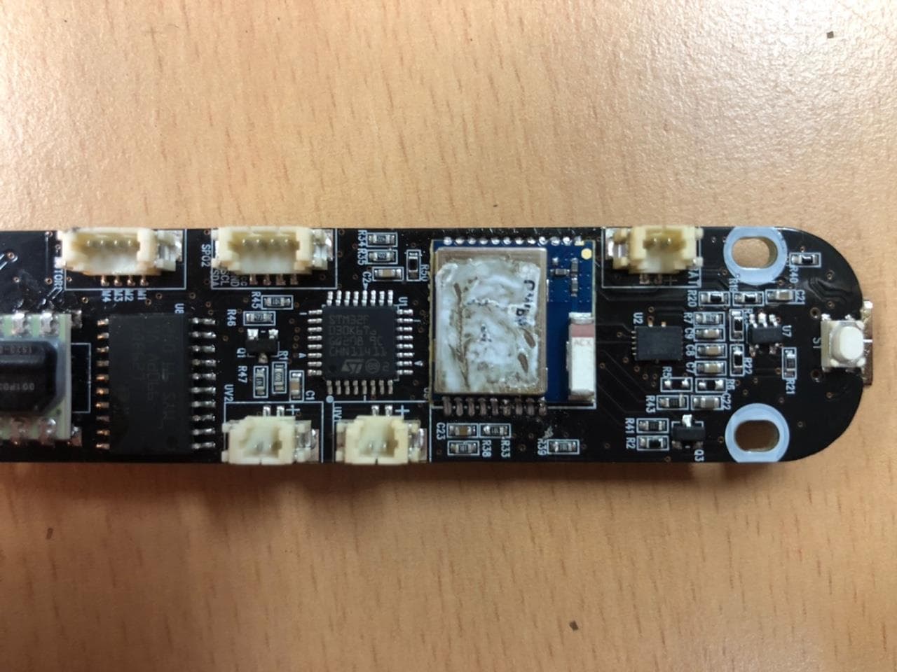
Click to zoom
Application Details
- Equipment Class
- DTS - Digital Transmission System
- Date of Grant
- Jan 16, 2023
- Application Purpose
- Original Equipment
- Date of Application
- Jan 16, 2023
- Equipment Note
- SMARTBREATHE-AIR
- Frequency Range
- 2402.00000000 - 2480.00000000
- Company
- ADD ABLE Co.,Ltd
- Country
- South Korea
Documents & Files
Document Text
Text extracted from the exhibit documents filed with the FCC. Open a document above to read the original.
Users Manual
Smart Breathe Air Detail Manual - 1 - Contents User Guide 2 Before Use 2 Precautions for using Smart Breathe Air About Smart Breathe Air 4 Components 5 Part Name 6 Function of each part How to use Smart Breathe Air 8 Bluetooth Connection Smart Breathe Air Management 9 Mouthpiece 9 Body About Smart Breathe Application 10 Sign up 11 Data 11 Training 12 Measurement 13 Measurement Records Appendix 14 Product Specifications and Characteristics 14 Service & Support 14 Copyright - 2 - User Guide Before use Please read this User Manual before use to ensure safe and use of the product. ž The contents of this User Manual may differ from the actual ones depending on the software version of the product, the circumstances of the service provider, and the specifications of the model, and the images in this User Manual may differ from the actual ones. Some of the contents are subject to change without notice to users to improve performance. ž Bluetooth connection is required to use some services in the application. ž If the product software provided by the Company is arbitrarily changed or obtained through an unofficial route and downloaded to the product the product may malfunction or an error may occur. This infringes on the rights of the Company and the software licensor and is not covered by warranty service. ž Works and contents such as software, images, etc. used in this product are copyrighted works permitted for limited use in accordance with the agreement between the Company and the respective copyright holders. Extracting them arbitrarily and using it for other purposes, such as commercial purposes, constitutes an act of infringing the copyright of the copyright holders, and the user will be responsible for this infringement. ž The basic applications or services provided with this product are subject to change or suspension without notice due to unavoidable circumstances. In this case, please contact the customer service center. We will respond sincerely. Precautions for using Smart Breathe Air This product is not intended to be a substitute for professional medical advice, diagnosis, treatment, or care. Before you make any decision or take an action that may affect your health, please consult with a doctor or other qualified health care provider. ž If you experience any abnormal symptoms such as chest pain or vomiting while using the product, stop using it immediately. ž We recommend that those with severe underlying medical conditions and those with diseases fully understand how to use it before using it. ž Do not use this product while driving. This may be illegal in some countries or regions. And lack of attention may lead to a risk of accidents. ž Do not shock or damage the product or battery. ž Be careful not to let any conductive material (metal, liquid, etc.) come into contact with the charger connector. ž If the product is damaged or has a problem, stop using it immediately and contact the customer service. - 3 - ž The optimum operating temperature for this product is 85°C to 40°C. Higher or lower temperatures than the optimum one may damage the product or shorten the battery life. ž Place the product in a dry place away from moisture. ž Using uncertified software may cause damage to the product or mobile device. In this case, the Company and the place of purchase are not responsible for the damage. - 4 - About Smart Breathe Air The Smart Breathe Air is a wellness device that connects to your mobile device to help you breathe properly and healthily in your daily life. It records your breathing data and visually presents them to you through a dedicated application. Components Please check the simple user manual for the components provided at the time of purchase. ž Components are for Smart Breathe Air only and may not be compatible with other devices. ž Supplied components, separately sold items, and images are subject to change depending on region and head office circumstances. ž Product appearance and specifications are subject to change without notice for performance improvement. ž You can purchase optional items on the sales website. When purchasing an optional accessory, first check whether it is compatible with the model you are using. ž For optional products, be sure to purchase genuine products provided by the company. The use of non-genuine accessories may cause deterioration or malfunction of the product, which will not be covered under warranty. - 5 - Part Name Mouthpiece UV Germicidal Lamp Control Fan Oxygen Saturation Contact Part Power Button Auto load button Manual load control button Battery LED UV Sterilization LED Reset button - 6 - Function of each part Mouthpiece ž The basic component mouthpiece can be used, and a disposable paper mouthpiece sold separately can also be used. ž The mouthpiece (pc material) can be reused after washing with water, but disposable paper mouthpieces are recommended to be discarded after use once. Oxygen saturation contact part ž Oxygen saturation can be measured only in individual training, and on/off operation of oxygen saturation measurement is possible in the personal training setting window. ž To measure oxygen saturation, you should touch the contact part with your finger for at least 5 seconds on average, and measurement may not be possible due to movement or surrounding environment during measurement. ※ Oxygen saturation numerical range Oxygen saturation is not data for medical diagnosis. Please use it for simple reference only. Oxygen SaturationState 80% or lessDangerous, Severe hypoxia 81% - 90%Warning, hypoxia alert 91% - 100%Normal range Load Level ž The load level is divided into a total of 15 levels. ž The load gets stronger as you go from level 1 to level 15. In level 15, the control fan is fully open. Automatic load button ž The user can operate it through a button, and the function turns on automatically according to the situation when using the software. ž When using the spirometry and level test functions in the dedicat…
Text truncated - open the document above for the full version.
Cover Letter(s)
ADD ABLE Co.,Ltd 314, Industry-Academic Cooperation Center, Kongju national university, 1223-24, Cheonan-daero, Seobuk-gu, Cheonan-si, Chungcheongnam-do, Republic of Korea Tel. +82-41-587-5030 Jan , Vista Laboratories, Inc. 1261 Puerta Del Sol San Clemente, Ca 92673 Family Model Letter The difference between SMARTBREATHE-AIR(Blue) and SMARTBREATHE-AIR(Gold) is the color difference of the product. Basic model name SMARTBREATHE-AIR(Blue) Variant model name SMARTBREATHE-AIR(Glod) Sicerely, Applicant’s company name: ADD ABLE Co.,Ltd Applicant’s company address: 314, Industry-Academic Cooperation Center, Kongju national university, 1223-24, Cheonan-daero, Seobuk-gu, Cheonan-si, Chungcheongnam-do, Republic of Korea Applicant’s signature: Applicant’s name / title: Jae-ho, Son / General Manager Email: [email protected] 202309
Cover Letter(s)
Date: 04/17/2018 VCB_F-01: Operating Procedures Form – FCC Authorization v02 Page 1 of 1 ADD ABLE Co.,Ltd Federal Communications Commission Authorization and Evaluation Division 1435 Oakland Mills Road Columbia, MD 21046 Date: 2023-01-09 SUBJECT: FCC Application for (FCC ID: 2A9W2SBAA-AIR-BLUE) To Whom It May Concern: We, the undersigned, hereby authorize David Zhang in Vista Laboratories, Inc. on our behalf, to apply to the Federal Communications Commission on our equipment. Any and all acts carried out by Vista Laboratories, Inc. on our behalf shall have the same effect as acts of our own. This is to advise that we are in full compliance with the Anti- Drug Abuse Act. We, the applicant, are not subject to a denial of federal benefits pursuant to Section 5301 of the Anti-Drug Act of 1988, 21 USC853a, and no party to the application is subject to a denial of federal benefits pursuant to that section. Sincerely, (Must be signed by the person that is listed on the FCC Website) Client’s signature: Client’s name & title: Jae-ho, Son / General Manager Contact information / address: +82-41-587-5030 / 314, Industry-Academic Cooperation Center, Kongju national university, 1223-24, Cheonan-daero, Seobuk-gu, Cheonan-si, Chungcheongnam-do, Republic of Korea
Cover Letter(s)
Date: 04/17/2018 VCB_F-01: Operating Procedures Form – FCC Confidentiality v03 Page 1 of 1 ADD ABLE Co.,Ltd Federal Communications Commission Authorization and Evaluation Division Confidentiality Request regarding application for certification of FCC ID: 2A9W2SBAA- AIR-BLUE Pursuant to Sections 0.457 and 0.459 of the Commission’s Rules, we hereby request confidential treatment of information accompanying this application as outlined below: Type of Confidentiality Requested Exhibit Type ☐Short Term ☒Permanent Block Diagrams ☒Short Term External Photos ☒Short Term ☐Permanent* Internal Photos ☐Short Term ☒Permanent Operation Description ☐Short Term ☒Permanent Parts List/BOM ☐ Short Term ☒Permanent Schematics ☒Short Term Test Setup Photos ☒Short Term ☐Permanent* User manual *Requires further justification before permanent confidentiality will be allowed. The above materials contain trade secrets and proprietary information not customarily released to the public. The public disclosure of these materials may be harmful to the applicant and provide unjustified benefits to its competitors. Permanent Confidentiality: The applicant requests the exhibits listed above as permanently confidential be withheld from public review due to materials that contain trade secrets and proprietary information not customarily released to the public. Short-Term Confidentiality: Pursuant to DA04-1705 June 15, 2004 of the Commission’s public notice, we also request temporary confidential treatment of information accompanying this application as outlined below for an initial period of 180 days. Sincerely, Client’s signature: Client’s name & title: Jae-ho, Son / General Manager Contact information / address: : : +82-41-587-5030 / 314, Industry-Academic Cooperation Center, Kongju national university, 1223-24, Cheonan-daero, Seobuk-gu, Cheonan-si, Chungcheongnam-do, Republic of Korea
External Photos
FCC ID: 2A9W2SBAA-AIR-BLUE Page 1 of 4 Upper Lower FCC ID: 2A9W2SBAA-AIR-BLUE Page 2 of 4 Side 1 Side 2 FCC ID: 2A9W2SBAA-AIR-BLUE Page 3 of 4 Side 3 Side 4 FCC ID: 2A9W2SBAA-AIR-BLUE Page 4 of 4 Ant □
ID Label/Location Info
FCC ID: 2A9W2SBAA-AIR-BLUE Copyright Ⓒ 2022, KRL Co., Ltd. SAMPLE LABEL & LOCATION ^
Internal Photos
FCC ID: 2A9W2SBAA-AIR-BLUE Page 1 of 3 Main Board Main Board FCC ID: 2A9W2SBAA-AIR-BLUE Page 2 of 3 Sub Board Sub Board FCC ID: 2A9W2SBAA-AIR-BLUE Page 3 of 3 Sub Board Sub Board
RF Exposure Info
FCC ID: 2A9W2SBAA-AIR-BLUE * SAR evaluation - Min. transmitting frequency = 2402 MHz - Min. test separation distance = 5 mm -Max. Power with tune-up tolerance = - 0.11 dBm = 0.97 mW (Measured Maximum power = - 0.61 dBm ± 0.5dB) Step 1) SAR Test exclusion thresholds for 100MHz to 6GHz at test separation distance ≤ 50 mm = Used [(max.power of channel, including tune-up torelance, mW)/(min. test separation distance, mm)] * [√f(GHz)] = [ 0.97 / 5 ] * [ √ 2.402 ] = 0.301 ≤ 3, for 1g SAR Thus, SAR for this device is not required. Step 2) SAR Test exclusion thresholds for 100MHz to 1500MHz at test separation distance > 50 mm = N/A [Threshold at 50mm in step 1) + (test separation distance - 50 mm) * (√f(MHz)/150] mW Step 3) SAR Test exclusion thresholds for 1500MHz to 6GHz at test separation distance > 50 mm = N/A [Threshold at 50mm in step 1) + (test separation distance - 50 mm) * 10] mW
Test Report
AT7020-E3R0HBAT/LF REV:4 PAGE:1/10 ACX Advanced Ceramic X Features Monolithic SMD with small, low-profile and light-weight type. Wide bandwidth Applications 2.4GHz WLAN, Home RF, Bluetooth Modules, etc. Specifications Part Number Operating Frequency (MHz) Peak Gain (dBi typ.) Average Gain (dBi typ.) VSWR Impedance AT7020 -E3R0HBA_ 2400~2500 1.3dBi (XZ-V) -0.5dBi (XZ-V)2 max. 50 Q’ty/Reel (pcs) : 1,000 pcs Operating Temperature Range : -40 ~ +85 o C Storage Temperature Range : -40 ~ +85 o C Storage Period : 12 months max. Power Capacity : 2W max. Part Number Type AT : Antenna Dimensions ( L × W ) 7.0× 2.0 mm Material Code E Initial center frequency 3R0=3000MHz Specification Code HBA Packaging T: Tape & Reel B: Bulk Soldering =lead-containing /LF=lead-free Terminal Configuration No. Terminal Name No. Terminal Name Feeding Point NC NC NC AT7020 Series Multilayer Chip Antenna A CX AT 7020 - E 3R0 HBA AT7020-E3R0HBAT/LF REV:4 PAGE:2/10 ACX Advanced Ceramic X Dimnsions and Recommended PC Board Pattern Mark L W L1 W1 T a Dimensions 7.0±0.2 2.0±0.2 2.6±0.2 0.5±0.2 2.0+ 0.1/-0.2 0.5±0.3 With Matching Circuits (Unit in mm) *Line width should be designed to match 50 characteristic impedance, depending on PCB material and thickness. Unit : mm a T L1 W1 L W ACX Top view Bottom view Side view (Matching circuit and component values will be different, depending on PCB layout) 0.83 2.8 1 1.6 1.6 1 0.8 1.83 0.8 1 2 2 2 10 4.87 2.7 nH A CX 1.8 nH AT7020-E3R0HBAT/LF REV:4 PAGE:3/10 ACX Advanced Ceramic X Typical Electrical Characteristics (T=25 o C) Test Board (Unit in mm) Return Loss/With Matching Circuits 4.87 40 20 Ground No Ground 10 Antenna AT7020-E3R0HBAT/LF REV:4 PAGE:4/10 ACX Advanced Ceramic X Radiation Patterns XZ cut @2.45GHz Vertical Horizontal YZ cut @2.45GHz Vertical Horizontal XZ-V/XZ-H YZ-V/YZ-H XY cut @2.45GHz Vertical Horizontal XY-V/XY-H 180 o 270 o 0 o 90 o X Z Y XY-cut scanning direction 180 o 270 o 0 o 90 o X Z Y XZ-cut scanning direction 180 o 270 o 0 o 90 o X Z Y YZ-cut scanning direction AT7020-E3R0HBAT/LF REV:4 PAGE:5/10 ACX Advanced Ceramic X AT7020-E3R0HBA on mobile phone layout Evaluation board (Unit in mm) Return Loss/With Matching Circuits 2 40 100 5 9 Ground No ground Via Antenna 3.3 nH 1.5 nH AT7020-E3R0HBAT/LF REV:4 PAGE:6/10 ACX Advanced Ceramic X Radiation Patterns XZ cut @2.45GHz Vertical Horizontal YZ cut @2.45GHz Vertical Horizontal XZ-V/XZ-H YZ-V/YZ-H XY cut @2.45GHz Vertical Horizontal XY-V/XY-H 180 o 270 o 0 o 90 o X Z Y XY-cut scanning direction 180 o 270 o 0 o 90 o X Z Y XZ-cut scanning direction 180 o 270 o 0 o 90 o X Z Y YZ-cut scanning direction AT7020-E3R0HBAT/LF REV:4 PAGE:7/10 ACX Advanced Ceramic X Taping Specifications Tape & Reel Dimensions (Unit: mm) vs. Quantity (pcs) Type A A’ B C D E F T Quantity/per reelTape material AT7020 4.0± 0.1 4.0± 0.1 2.3± 0.1 7.3± 0.1 2.0± 0.05 5.5± 0.1 12.0± 0.1 2.20± 0.1 1,000pcs Plastic (Embossed) Reel Dimensions (Unit: mm) Leader and Trailer Tape Type W2 W3 W4 W5 AT5020 178±1 60±0.5 1.485±0.5 13±0.5 F A’ D E 1.75 ± 0.1 AB EMBOSS TA P E T C ∣ Trailer End Trailer (160 mm min.) Leader End Empty Compartments with Cover Tape (500 mm min.) W2 13.5±0.5 2.5±0.5 Label Label: Customer’s Name, ACX P/N, Q’ty, Date, ACX Corp. W4 W5 W3 AT7020-E3R0HBAT/LF REV:4 PAGE:8/10 ACX Advanced Ceramic X Peel-off Force Peel-off force should be in the range of 0.2 – 1.20 N at a peel-off speed of 300±10 mm/min . Storage Conditions (1) Temperature: 5 ~35°C, relative humidity (RH): 45~75%. (2) Non-corrosive environment Notes The contents of this data sheet are subject to change without notice. Please confirm the specifications and delivery conditions when placing your order. Peeling Direction Top Cover Tape Carrier Tape <10 0 AT7020-E3R0HBAT/LF REV:4 PAGE:9/10 ACX Advanced Ceramic X Mechanical & Environmental Characteristics Item Requirements Procedure Solderability 1. No apparent damage 2. More than 95% of the terminal electrode shall be covered with new solder 1. Preheat: 120 5 o C 2. Solder: 245 5 o C for 5 1 sec Soldering strength (Termination Adhesion) 1. 1kg minimum 1. Solder specimen onto test jig. 2. Apply push force at 0.5mm/s until electrode pads are peeled off or ceramic are broken. Pushing force is applied to longitude direction Deflection (Substrate Bending) 1. No apparent damage 1. Solder specimen onto test jig (FR4, 0.8mm) using the recommend soldering profile. 2. Apply a bending force of 1mm deflection ` Heat/Humidity Resistance 1. No apparent damage 2. Fulfill the electrical specification after test 1. Temperature: 85 2 o C 2. Humidity: 90% ~ 95% RH 3. Duration: 1000±48hrs 4. Recovery: 1-2hrs Thermal shock (Temperature Cycle) 1. No apparent damage 2. Fulfill the electrical specification after test 1. One cycle/step 1:125 ± 5C for 30 min step 2:- 40 ± 5C for 30 min 2. No of cycles:100 3. Recovery:1-2 hrs Low Temperature Resistance 1. No apparent damage 2. Fulfill the electrical specification after test 1. Temperature: -40 o 5 o C 2. Duration: 500 ±24hrs 3. Recovery: 1-2hrs 90mm Pressure Rod R230 AT7020-E3R0HBAT/LF REV:4 PAGE:10/10 ACX Advanced Ceramic X Soldering Conditions Typical Soldering Profile for Lead-free Process Reflow Soldering : Notes The contents of this data sheet are subject to change without notice. Please confirm the specifications and delivery conditions when placing your order. Temperature ( o C) Pre-heating 60-180s Time (s.) 20s max. 260 o C 150-200 o C 217 o C 60-150s. Advanced Ceramic X Corp. 16 Tzu Chiang Road, Hsinchu Industrial District Hsinchu Hsien 303, Taiwan TEL:886-3-5987008 FAX:886-3-5987001 E-mail: [email protected] http://www.acxc.com.tw
Test Report
R Report No.: KR0140-RF2301-001 EMCLabs-QPF-26-25 [Enactment_00 / 2022. 09. 07] Page 1 / 42 This test report shall not be reproduced except in full, Without the written approval. 본 시험성적서는 (주)ABCD의 서면 동의 없이 무단 전제 및 복사를 할 수 없습니다. Test Report 1. Client ᆞName : ADD ABLE Co.,Ltd ᆞAddress : 314ho,1223-24, Cheonan-daero, Seobuk-gu, Cheonan-si, Chungcheongnam-do, Republic of Korea 2. Use of Report : FCC Approval 3. Sample Description ᆞProduct Name : SMARTBREATHE-AIR ᆞModel Name : SMARTBREATHE-AIR(Blue) 4. Date of Receipt : 2022-11-02 5. Date of Test : 2022-12-01 ~ 2022-12-28 6. Test Method : FCC Part 15 Subpart C 15.247 RSS-247 Issue 2(2017-02), RSS-GEN Issue 5(2019-03) 7. Test Results : Refer to the test results This test report must not be reproduced or reproduced in any way. The results shown in this test report are the results of testing the samples provided. This test report is prepared according to the requirements of ISO / IEC 17025. Affirmation Tested by Dae-Seong, Choi (signature) Technical Manager Yong-Min, Won (signature) Jan 05, 2023 EMC Labs Co., Ltd. (seal) R Report No.: KR0140-RF2301-001 EMCLabs-QPF-26-25 [Enactment_00 / 2022. 09. 07] Page 2 / 42 This test report shall not be reproduced except in full, Without the written approval. 본 시험성적서는 (주)ABCD의 서면 동의 없이 무단 전제 및 복사를 할 수 없습니다. Contents 1. Applicant & Manufacturer & Test Laboratory Information··································· 4 2. Equipment under Test(EUT) Information······················································· 5 3. Test Summary······················································································· 6 4. Used equipment on test·········································································· 7 5. Antenna Requirement·············································································· 8 6. 6 dB Bandwidth····················································································· 9 7. Maximum Peak Output Power···································································· 13 8. Peak Power Spectral Density····································································· 16 9. TX Radiated Spurious Emission and Conducted Spurious Emission····················· 19 10. Conducted Emission··············································································· 36 APPENDIX APPENDIX I TEST SETUP············································································ 39 APPENDIX II UNCERTAINTY·········································································· 41 R Report No.: KR0140-RF2301-001 EMCLabs-QPF-26-25 [Enactment_00 / 2022. 09. 07] Page 3 / 42 This test report shall not be reproduced except in full, Without the written approval. 본 시험성적서는 (주)ABCD의 서면 동의 없이 무단 전제 및 복사를 할 수 없습니다. Version TEST REPORT NO. DATE DESCRIPTION KR0140-RF2301-001 Jan 05, 2023 Initial Issue R Report No.: KR0140-RF2301-001 EMCLabs-QPF-26-25 [Enactment_00 / 2022. 09. 07] Page 4 / 42 This test report shall not be reproduced except in full, Without the written approval. 본 시험성적서는 (주)ABCD의 서면 동의 없이 무단 전제 및 복사를 할 수 없습니다. 1. Applicant & Manufacturer & Test Laboratory Information 1.1 Applicant Information Applicant ADD ABLE Co.,Ltd Applicant Address 314ho,1223-24, Cheonan-daero, Seobuk-gu, Cheonan-si, Chungcheongnam-do, Republic of Korea Contact Person JaeHo Son Telephone No. +82-41-587-5030 Fax No. - E-mail [email protected] 1.2. Manufacturer Information Manufacturer ADD ABLE Co.,Ltd Manufacturer Address 314ho,1223-24, Cheonan-daero, Seobuk-gu, Cheonan-si, Chungcheongnam-do, Republic of Korea 1.3 Test Laboratory Information Laboratory EMC Labs Co., Ltd. Laboratory Address 100, Jangjateo-ro, Hobeop-myeon, Icheon-si, Gyeonggi-do, Republic of Korea Contact Person Yongmin Won Telephone No. +82-31-637-8895 Fax No. +82-505-116-8895 FCC Designation No. KR0140 FCC Registration No. 580000 IC Site Registration No. 28751 R Report No.: KR0140-RF2301-001 EMCLabs-QPF-26-25 [Enactment_00 / 2022. 09. 07] Page 5 / 42 This test report shall not be reproduced except in full, Without the written approval. 본 시험성적서는 (주)ABCD의 서면 동의 없이 무단 전제 및 복사를 할 수 없습니다. 2. Equipment under Test(EUT) Information 2.1 General Information Product Name SMARTBREATHE-AIR Model Name SMARTBREATHE-AIR(Blue) FCC ID 2A9W2SBAA-AIR-BLUE Rated Voltage DC 3.7 V 2.2 Additional Information Operating Frequency 2 402 MHz ~ 2 480 MHz Number of channel 40 Modulation Type GFSK Antenna Type Chip Antenna Antenna Gain 1.3 dBi Firmware Version 1.0 Hardware Version 1.0 Test software nRF_DTM 2.3 Test Frequency Test mode Test Frequency (MHz) Low Frequency Middle Frequency High Frequency BLE 2 402 2 442 2 480 2.4 Used Test Software Setting Value Test Mode Setting Item Power BLE 0 2.5 Mode of operation during the test - The EUT continuous transmission mode during the test with set at Low Channel, Middle Channel, and High Channel. To get a maximum radiated emission levels from the EUT, the EUT was moved throughout the XY, YZ, XZ planes. 2.6 Modifications of EUT - None R Report No.: KR0140-RF2301-001 EMCLabs-QPF-26-25 [Enactment_00 / 2022. 09. 07] Page 6 / 42 This test report shall not be reproduced except in full, Without the written approval. 본 시험성적서는 (주)ABCD의 서면 동의 없이 무단 전제 및 복사를 할 수 없습니다. 3. Test Summary Applied FCC Rule IC Rule Test Items Test Condition Result 15.203 - Antenna Requirement Conducted C 15.247(a) RSS-247 (5.2) 6 dB Bandwidth C - RSS GEN (6.7) Occupied Bandwidth (99%) C 15.247(b) RSS-247 (5.4) Maximum Peak Output Power C 15.247(e) RSS-247 (5.2) Peak Power Spectral Density C 15.247(d) RSS-247 (5.5) Conducted Spurious Emission C 15.247(d) 15.205 & 15.209 RSS-247 (5.5) RSS-GEN (8.9 & 8.10) Radiated Spurious Emission Radiated C 15.207 RSS-GEN (8.8) Conducted Emissions AC Line Conducted C Note 1: C=Complies NC=Not Complies NT=Not Tested NA=Not Applicable The sample was tested according to the following specification: ANSI C63.10:2013. Compliance was determined by specification limits of the applicable standard according to customer req…
Text truncated - open the document above for the full version.
Test Setup Photos
Below 30 MHz Below 1 GHz Above 1 GHz Conducted Emission
Contact Information
Applicant
Jae Ho Son(Manager)
Test Firm
EMC Labs Co., Ltd.Jong-Myoung Shin
Technical Specifications
| # | Rule Parts | Frequency Range | Power Output |
|---|---|---|---|
| 1 | 15C | 2.40 GHz - 2.48 GHz | 870.00 µW |