2A9X4A4832-01Proprietary secured wireless network
LTA Research and Exploration, LLC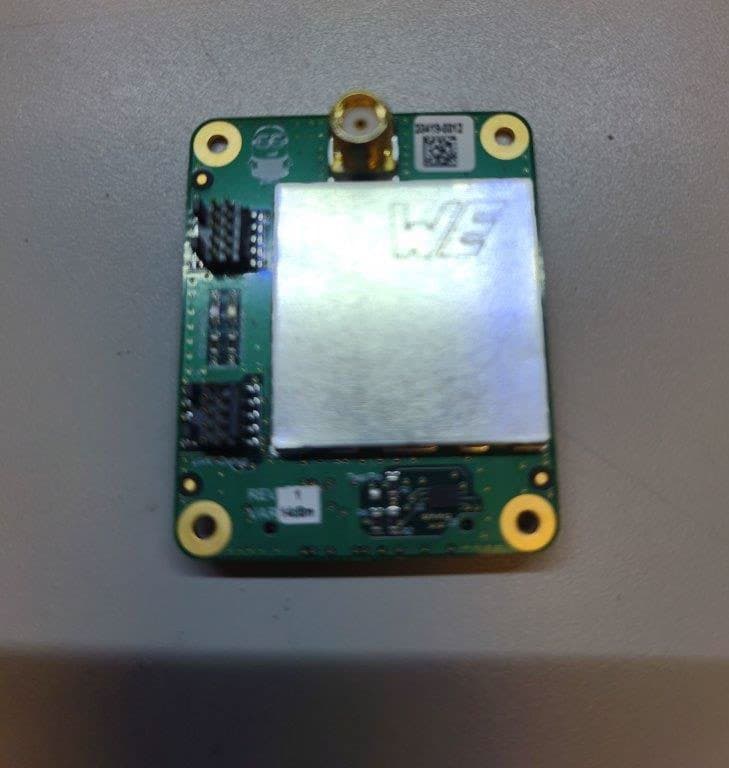
Click to zoom
Application Details
- Equipment Class
- DSS - Part 15 Spread Spectrum Transmitter
- Date of Grant
- Jul 23, 2023
- Application Purpose
- Original Equipment
- Date of Application
- Jul 18, 2023
- Equipment Note
- Proprietary secured wireless network
- Frequency Range
- 902.87500000 - 927.53500000
- Country
- United States
Documents & Files
Document Text
Text extracted from the exhibit documents filed with the FCC. Open a document above to read the original.
Users Manual
Version: V1.50 Title: Freeballooning Wireless Module Manual Subtitle Manual for FCC compliance for Wireless Module This document serves as a manual with FCC requirements for the freeballooning wireless module. Additional details on system operation can be found in the “DOC_00xxx_EDM Freeballooning Wireless System Theory of Operation Version 1.01a” Version Date Notes 1.00 01/11/2023 Initial Release 1.10 02/20/2023 Updated sections on antennas, rf connections, module labeling, testing specifications 1.20 05/01/2023 Added details on antenna installation to justify lack of unique connectors 1.30 06/10/2023 Added more details on module labeling and antenna installation. Added cover letter requesting professional installation 1.40 06/25/2023 Added details on RF exposure, and collocation of antennas Version: V1.50 Title: Freeballooning Wireless Module Manual Subtitle Manual for FCC compliance for Wireless Module 1. Applicable FCC Rules: 1.1. FCC Part 15 Subpart C, Section 15.247. 2. Operational Use Conditions (if applicable): 3. RF Exposure Considerations: 4. Antennas Approved for Use with this Module: 5. Module RF Connector Information Figure 1: Module RF Connector 6. Module Cabling 7. Label and Compliance Information Figure 2: Module Label Figure 3. Module Label Location 8. Manual Statements 9. Information on test modes and additional testing requirements 10. Additional testing, Part 15 subpart B disclaimer 11. FCC Warning Version: V1.50 Title: Freeballooning Wireless Module Manual Subtitle Manual for FCC compliance for Wireless Module 1. Applicable FCC Rules: 1.1. FCC Part 15 Subpart C, Section 15.247. 2. Operational Use Conditions (if applicable): 2.1. There is no power supply on the module and so the carrier board must have a conditioned power supply that meets the following specifications: 2.1.1. Input power shall be conditioned DC where transients induced in the system or by lightning are handled by the carrier board. 2.1.2. The operating voltage shall be +3VDC to +3.6VDC. 2.1.3. The maximum transient voltage supplied to device shall be no more than 4.1V for <10 milliseconds. 80% derating for 3.3V, upper bound 2.1.4. The minimum transient voltage supplied to device shall be no less than 2.6V for <10 milliseconds. 80% derating for 3.3V, lower bound 2.2. All IOs that are exposed to the carrier board are not protected via buffering or isolation in any way. The carrier board must ensure proper buffering and isolation is provided to signals that are routed from the board-board connector to the carrier board. Unused IO should be left open circuited. 2.3. Only use certified antennas described in this document and LTA Research and Exploration defined installation teams and processes when installing a module + RF cabling + RF antenna in an end application. 3. RF Exposure, Radio Collocation, and Installation Restrictions: 3.1. Use of this module is not authorized for portable configurations 3.2. Integration of the module into any enclosure requires approval of LTA 3.3. This module is approved only for integration into specific enclosures where separation distance between antennas and users is >20cm 3.4. Minimum installation distance between antennas of this system and other systems is 4.5m. This module is not approved for collocation with other radios; separate authorization may be required when module antennas are located near other antennas of other transmitters which operate simultaneously Version: V1.50 Title: Freeballooning Wireless Module Manual Subtitle Manual for FCC compliance for Wireless Module 4. Antennas Approved for Use with this Module: Approved antennas list: Manufacturer Antenna Description Type Peak Gain (dBI) Impedance (Ω) Connector Type Notes TE Connectivity TRAB8903N Phantom Radome Omnidirectional 3 50 NMO 1 TE Connectivity TRAB8903NP Phantom Radome Omnidirectional 3 50 N-TYPE 2 Notes: 1. Antenna was tested for compliance. 2. Antenna is approved by similarity with equivalent or lesser gain 5. Module RF Connector Information Figure 1: Module RF Connector 5.1. Connector Type: Surface Mount SMA Jack; Female Socket 5.2. Manufacturer: Amphenol RF 5.3. Manufacturer P/N: 132134-10 6. Module Cabling 6.1. Cabling is not sufficiently long at any location to require additional power output to compensate 6.2. Module will connect to the following cabling 6.2.1. Internal harness: 6.2.1.1. Type: RG195 Coaxial Cable 6.2.1.2. Quantity: 10 Locations 6.2.2. External Harness 6.2.2.1. Type: RG142 Coaxial Cable 6.2.2.2. Quantity: 1 Location Version: V1.50 Title: Freeballooning Wireless Module Manual Subtitle Manual for FCC compliance for Wireless Module 6.2.3. A statement signifying “the device, antenna assembly, and the antenna are not to be removed or handled by individuals unapproved by LTA” shall be clearly visible on the outside of the enclosure. 6.2.4. End product will only be accessed and/or removed by a Licensed A&P. 6.2.5. If the antenna needs to be removed, the same procedures for installing will be used to track name and time. 7. Label and Compliance Information 7.1. The module must be properly labeled with the text “FCC ID: 2A9X4A4832-01” 7.1.1. Module label design and dimensions are given in Figure 2 7.1.2. Module label location on module is given in Figure 3 7.2. The following statements must be included on the exterior of the finished product 7.2.1. “Contains FCC ID: 2A9X4A4832-01” 7.2.2. This device complies with Part 15 of the FCC Rules. Operation is subject to the following two conditions: (1) this device may not cause harmful interference, and (2) this device must accept any interference received, including any interference that may cause undesired operation. 7.2.3. External label design and dimensions are given in Figure 4 7.2.4. External label location on module is given in Figure 5 Version: V1.50 Title: Freeballooning Wireless Module Manual Subtitle Manual for FCC compliance for Wireless Module Figure 2: Module Label Figure 3. Module Label Location Version: V1.50 Title: Freeba…
Text truncated - open the document above for the full version.
Attestation Statements
CKC Certification Services, LLC CB: US0103; NB/AB: 0976 5046 Sierra Pines Drive Mariposa, CA 95338 Phone: 1 800-500-4EMC (4362) Fax: 209-787-5568 Email: [email protected] APP-FCC-A Page 1 of 2 Rev 2 APP-FCC-A Applicant Attestation Applicant Information Company Name: LTA Research and Exploration, LLC Contact Name: Max Fors Contact Title: Senior Mechanical Engineer Company Address: 642 N Pastoria Ave Sunnyvale, CA 94085 Telephone No: 650-213-6220 Facsimile No: N/A Email Address: [email protected] Certification Type / Equipment Identification Certification Program: Radio Certification Certification Number: 2A9X4A4832-01 The equipment identified above ☐ is / ☒ is not “covered” equipment prohibited from receiving an equipment authorization pursuant to 47 CFR Part 2, Subpart J, §2.903. The applicant identified above ☐ is / ☒ is not identified on the FCC’s “Covered List” as an entity, affiliate, or subsidiary which produces equipment on the “Covered List” or identified as an entity which has rebranded or relabeled equipment produced by entities identified on the “Covered List.” I hereby attest and certify that the above statements are true and correct. Signature of Authorized Individual: 1 Printed Name: Scott Nicholes Title of authorized signature: CFO Date 2-21-23 Note this attestation shall be signed by the applicant or their direct appointee within the same legal entity. A third party agent is not permitted to sign on behalf of the applicant. 1 Signature is not subject to the FCC’s authorized individual policy (KDB 852134) and may be signed by any appropriate company official. CKC Certification Services, LLC CB: US0103; NB/AB: 0976 5046 Sierra Pines Drive Mariposa, CA 95338 Phone: 1 800-500-4EMC (4362) Fax: 209-787-5568 Email: [email protected] APP-FCC-A Page 2 of 2 Rev 2 Attachment A – Additional Information The FCC’s “Covered List” includes certain “telecommunications equipment” and “video surveillance equipment” produced by specific manufacturers, their Affiliates or Subsidiaries and including any products produced by these entities which are rebranded or relabeled by other entities. (191, 184, 185, 188) 2 The FCC claims the identified equipment poses an unacceptable risk to United States national security. Telecommunications Equipment (195) : Any equipment used in fixed or mobile networks that provides advanced communications service, provided the equipment includes or uses electronic components, as defined under section 1.50001(c). Video Surveillance Equipment (205) : Any equipment that is used in fixed and mobile networks that provides advanced communications service in the form of a video surveillance service, provided the equipment includes or uses electronic components. Advanced Communications Service (195, 205) Any equipment that can be used in such a fixed or mobile broadband network to enable users to originate and receive high quality voice, data, graphics, and video telecommunications service using any technology with connection speeds of at least 200 kbps in either direction. Affiliate (183) : An entity that (directly or indirectly) owns or controls, is owned or controlled by, or is under common ownership or control with, another entity, where the term “own” means to have, possess, or otherwise control an equity interest (or the equivalent thereof) of more than 10 percent. Subsidiary (184) : Any entity in which such named entity directly or indirectly (1) holds de facto control or (2) owns or controls more than 50% of the total voting power of the entity’s outstanding voting stock. Useful Links: FCC Covered List https://www.fcc.gov/supplychain/coveredlist 47 CFR Part 2 Subpart J (including 2.903 and 2.911) https://www.ecfr.gov/current/title-47/chapter-I/subchapter-A/part-2/subpart-J FCC KDB System: https://apps.fcc.gov/oetcf/kdb/index.cfm FCC Report and Order 22-84 https://docs.fcc.gov/public/attachments/FCC-22-84A1.pdf 2 Parenthetical references are citations of paragraph numbers in FCC Report and Order FCC 22-84 (ET Docket 21.232).
Attestation Statements
Attestation For United States Agent for Service of Process Self-Designation for US Based Manufacturers Only CKC CS PUB FCC AFSOP Self Designation v3 Applicant / Equipment Manufacturer Information Company Name: LTA Research LLC Grantee Code: 2A9X4 FRN: 0033252016 Applicant Attestation The undersigned hereby consents: a) to self-designation as US Agent for Service of Process; and b) to accept responsibility and obligation to maintain self-designation for no less than one year after either all marketing and importation of the applicable equipment within the U.S has been permanently terminated, or the conclusion of any Commission-related administrative or judicial proceeding involving the equipment, whichever is later; and c) to accept service of process in the US for matters related to the applicable equipment and at the physical address and email address identified in the applicant’s grantee code registration for equipment authorization applications under certification pursuant to 47 CFR Part 2 Subpart J; and d) to maintain current grantee code information on file in accordance with 47 CFR Part 2.929. Signature Applicant: Daniel Morgan LTA Research LLC Date: 06/10/2023 Printed Name: Daniel Morgan
Cover Letter(s)
LTA Research 642 N. Pastoria Ave Sunnyvale, CA 94085 12/16/2022 To Whom It May Concern: We hereby delegate CKC Certification Services, LLC (CKC CS) power of attorney to act on our behalf in matters pertaining to certification of products, provided that CKC CS shall not take any action on our behalf without our prior written authorization. The actions of CKC CS shall be considered the same as our own. Sincerely, Scott Nicholes Chief Financial Officer
Cover Letter(s)
LTA Research 642 N. Pastoria Ave Sunnyvale, CA 94085 2/14/23 To Whom It May Concern: I hereby appoint Scott Nicholes to sign letters and applications for any filings with regulatory agencies on our behalf, and to receive and exchange data between our company, the agents company and the agency in connection with certification for any products that our company owns or manufactures. Sincerely, Daniel Morgan Vice President Engineering LTA Research LLC
Cover Letter(s)
LTA Research 642 N. Pastoria Ave Sunnyvale, CA 94085 06/28/2023 Federal Communications Commission Office of Engineering and Technology 7435 Oakland Mills Road Columbia, MD 21046 To Whom It May Concern: This letter is to request Limited Modular Approval in accordance with FCC Rule Part 15.212(b) for the certification request under FCC ID: 2A9X4A4832-01 This product is a Wireless MCU operating in the 902-928 MHz ISM band that provides a serial connection between up to 15 devices through a transparent wireless link and can be used in a rigid airship. Declaration of conditions. Y/N 15.212(a)(1) Condition Y (i) The radio elements of the module have their own shielding. The physical crystal and tuning capacitors may be located external to the shielded radio elements Y (ii) The module has buffered modulation/data inputs (if such inputs are provided) to ensure that the module will comply with part 15 requirements under conditions of excessive data rates or over-modulation. N (iii) The module has its own power supply regulation. N (iv) The module complies with the antenna and transmission system requirements of §§15.203, 15.204(b) and 15.204(c). The antennas will be professionally installed. Details on justification and request for professional installation are provided in the module manual. Y (v) The module was tested in a stand-alone configuration, i.e., the module was not inside another device during testing for compliance with part 15 requirements. Unless the transmitter module will be battery powered, it complies with the AC line conducted requirements found in §15.207. AC or DC power lines and data input/output lines connected to the module do not contain ferrites, unless they will be marketed with the module (see §15.27(a)). The length of these lines was the length typical of actual use or, if that length is unknown, at least 10 centimeters was used to ensure that there is no coupling between the case of the module and supporting equipment. Any accessories, peripherals, or support equipment connected to the module during testing were unmodified and commercially available (see §15.31(i)). Y (vi) The module is equipped with either a permanently affixed label or is capable of electronically displaying its FCC identification number. Y (vii) The module complies with any specific rules or operating requirements that ordinarily apply to a complete transmitter and the applicant has provided adequate instructions along with the module to explain any such requirements. Y (viii) The module complies with any applicable RF exposure requirements in its final configuration. The instructions provided with the module adequately explain any usage conditions or restrictions. LTA Research 642 N. Pastoria Ave Sunnyvale, CA 94085 Explanation of limitations for items not compliant with the above conditions. Section Detailed Explanations (if needed) (iii) There is no power supply regulation outside of some filtering. The carrier/mother board is expected to supply power within the specifications provided in the requirements specification for the radio module. (iv) Module antenna installation requires professional installation. List of additional restrictions or conditions of use for this module (optional). The radio module is to be used exclusively by the manufacturer, LTA. Methods used to address restrictions to ensure compliance for all finished products (optional). Internal analysis, review, and acceptance of the carrier/mother board meeting the radio module’s power supply specifications. I acknowledge on behalf of the applicant that compliance of this module in all final configurations is the responsibility of the applicant under the condition that the integrator follows all provided installation instructions. Sincerely, Daniel Morgan Daniel Morgan Vice President of Engineering LTA Research
Cover Letter(s)
LTA Research 642 N. Pastoria Ave Sunnyvale, CA 94085 12/6/2022 Federal Communications Commission 7435 Oakland Mills Road Columbia, MD 21046 Subject: Request for Permanent Confidentiality To whom it may concern: In accordance with 47CFR Section 0.457 and Section 0.459 pertaining to confidential material, we hereby request to hold permanently confidential all information contained within the below identified exhibits/document categories submitted pursuant to radio equipment certification requirements for FCC ID: 2A9X4A4832-01 1. Block Diagram 2. Operational Description 3. Schematics 4. Parts List / Tune-Up Procedure The above material contains trade secrets and proprietary information as specified by 47CFR 0.457(d) and technical data, which would customarily be guarded from competitors. The public disclosure of this information might be harmful to our company and provide unjustified benefits to our competitors. Sincerely, Scott Nicholes Chief Financial Officer LTA Research
Cover Letter(s)
Version: V1.50 Title: Freeballooning Wireless Module Manual Subtitle Manual for FCC compliance for Wireless Module COVER LETTER REQUESTING PROFESSIONAL INSTALLATION The following cover letter is to request professional installation of the installed antenna. In order to meet Section 15.203 Antenna Requirement this letter addresses the guidelines in KDB353028 D01 Antennas Part 15 Transmitters v01r01 Section A Part 2 Subpart (c) “Professional Installation” The section is copied below and each item addressed individually: c) Professional installation i) Professional installation must be justified in the filing, and grant condition must state “This device must be professionally installed.” This is written in the Limited Modular Application. ii) Professional installation does not permit use of any antenna with the transmitter; the permitted types of antenna must be specified. This is addressed in Section: ”Antennas Approved for Use with this Module” iii) The applicant should address the following items when justifying professional installation. (1) To qualify for professional installation, the applicant must explain why the hardware is not readily available to average consumer. This hardware is intended to be installed into a single experimental flight vehicle. This vehicle is not for consumers or the general public. Therefore, it will not be available to the average consumer. (2) Marketing—Device cannot be sold via retail to the general public or by mail order; it must be sold to authorized dealers or installers only. This hardware is intended to be installed into a single experimental flight vehicle. This vehicle is not for consumers or the general public. Therefore, it will not be sold to any person in any fashion. (3) Filing must show that intended use is not for consumers and general public; rather device is generally for industrial/commercial use. This hardware is intended to be installed into a single experimental flight vehicle. This vehicle is not for consumers or the general public. (4) Explain what is unique, sophisticated, complex, or specialized about the equipment that REQUIRES it to be installed by a professional installer? This hardware is intended to be installed into a single experimental flight vehicle. It will be used by personnel who will be required to enter and exit the vehicle, and will also need to be trained to interact with the hardware safely. Furthermore, this hardware is to be used as a specialized emergency system for the flight vehicle. Therefore Version: V1.50 Title: Freeballooning Wireless Module Manual Subtitle Manual for FCC compliance for Wireless Module controlled and trained interaction with the hardware is necessary in order to ensure its functionality is maintained. iv) Other professional installation requirements. (1) Installation must be controlled. (2) Installed by licensed professionals (e.g., device sold to dealer who hire installers). (3) Installation requires special training (e.g., special programming, access to keypad, field strength measurements made). Please see the below statements to address items (1) to (3) above - Certified radio modules are to be installed in an end product, carrier board + enclosure, by an LTA electrical engineer, LTA electronics technician, or a Licensed A&P. - End product will be installed into the aircraft by a Licensed A&P. - Only LTA electrical engineer, LTA electronics technician, or a Licensed A&P. who is approved by LTA will be permitted to install antennas onto the end product. - Only approved antennas may be installed onto the device. See “Section 4. Antennas Approved for Use with this Module” for approved antennas. - Installation must follow the restrictions listed in “Section 3: RF Exposure, Radio Collocation, and Installation Restrictions” - Approval to install antennas will follow training to perform at minimum the following process - The certified module’s antenna will be attached to the enclosure secured with loctite on the threaded connector - The installer name and date that it was installed along with module P/N and antenna P/N will be tracked. - A statement signifying “the device, antenna assembly, and the antenna are not to be removed or handled by individuals unapproved by LTA” shall be clearly visible on the outside of the enclosure. - End product will only be accessed and/or removed by a Licensed A&P. - If the antenna needs to be removed, the same procedures for installing will be used to track name and time.
External Photos
F2P28874A Page 1 of 1 2023-01-06 PHOTOGRAPHS: EXTERNAL LTA Research and Exploration, LLC - Model A4832_01 Test Assembly Bottom Module PCB with Shield
ID Label/Location Info
Sample ID Label: Sample ID Label Location:
Internal Photos
F2P28874A Page 1 of 7 2023-01-06 PHOTOGRAPHS: INTERNAL LTA Research and Exploration, LLC - Model A4832_01 Module PCB Top Order Number: F2P28874A Applicant: LTA Research and Exploration, LLC Model: A4832_01 F2P28874A Page 2 of 7 2023-01-06 Module PCB Bottom Order Number: F2P28874A Applicant: LTA Research and Exploration, LLC Model: A4832_01 F2P28874A Page 3 of 7 2023-01-06 Module PCB with Shield Order Number: F2P28874A Applicant: LTA Research and Exploration, LLC Model: A4832_01 F2P28874A Page 4 of 7 2023-01-06 Test Assembly Top Test Assembly Bottom Order Number: F2P28874A Applicant: LTA Research and Exploration, LLC Model: A4832_01 F2P28874A Page 5 of 7 2023-01-06 Test Fixture Top Order Number: F2P28874A Applicant: LTA Research and Exploration, LLC Model: A4832_01 F2P28874A Page 6 of 7 2023-01-06 U1 Order Number: F2P28874A Applicant: LTA Research and Exploration, LLC Model: A4832_01 F2P28874A Page 7 of 7 2023-01-06 U2 Radio Chip
RF Exposure Info
042216 Report Number: F2P28874A-C1-03E Page 1 of 8 Issue Date: 2023-07-18 F2 Labs 16740 Peters Road Middlefield, Ohio 44062 United States of America www.f2labs.com MPE TEST REPORT Manufacturer: LTA Research and Exploration, LLC 642 North Pastoria Avenue Sunnyvale, California 94085 USA Applicant: Same as Above Product Name: Freeballooning Wireless Module Model: A4832_01 FCC ID: 2A9X4A4832-01 Testing Commenced: 2022-12-01 Testing Ended: 2023-07-18 Test Results: In Compliance The EUT complies with the EMC requirements when manufactured identically as the unit tested in this report, including any required modifications. Any changes to the design or build of this unit subsequent to this testing may deem it non- compliant. Standards: • KDB447498 Order No(s): F2P28874A, F2P28874A-C1 Applicant: LTA Research and Exploration, LLC Model: A4832_01 042216 Report Number: F2P28874A-C1-03E Page 2 of 8 Issue Date: 2023-07-18 Evaluation Conducted by: Julius Chiller, Senior Wireless Project Engineer Report Reviewed by: Ken Littell, Vice President of Operations F2 Labs F2 Labs F2 Labs 26501 Ridge Road 16740 Peters Road 8583 Zionsville Road Damascus, MD 20872 Middlefield, OH 44062 Indianapolis, IN 46268 Ph 301.253.4500 Ph 440.632.5541 Ph 317.610.0611 This test report may be reproduced in full; partial reproduction only may be made with the written consent of F2 Labs. The results in this report apply only to the equipment tested. Order No(s): F2P28874A, F2P28874A-C1 Applicant: LTA Research and Exploration, LLC Model: A4832_01 042216 Report Number: F2P28874A-C1-03E Page 3 of 8 Issue Date: 2023-07-18 TABLE OF CONTENTS Section Title Page 1 ADMINISTRATIVE INFORMATION 4 2 SUMMARY OF TEST RESULTS/MODIFICATIONS 5 3 ENGINEERING STATEMENT 6 4 EUT INFORMATION AND DATA 7 5 RF EXPOSURE FOR DEVICE >20cm FROM HUMAN 8 Order No(s): F2P28874A, F2P28874A-C1 Applicant: LTA Research and Exploration, LLC Model: A4832_01 042216 Report Number: F2P28874A-C1-03E Page 4 of 8 Issue Date: 2023-07-18 1 ADMINISTRATIVE INFORMATION 1.1 Measurement Location: F2 Labs in Middlefield, Ohio. Site description and attenuation data are on file with the FCC's Sampling and Measurement Branch at the FCC Laboratory in Columbia, MD. 1.2 Measurement Procedure: All measurements were performed according to KDB558074. 1.4 Document History Document Number Description Issue Date Approved By F2P28874A- C1-03E First Issue 2023-07-18 K. Littell Order No(s): F2P28874A, F2P28874A-C1 Applicant: LTA Research and Exploration, LLC Model: A4832_01 042216 Report Number: F2P28874A-C1-03E Page 5 of 8 Issue Date: 2023-07-18 2 SUMMARY OF TEST RESULTS Test Name Standard(s) Results RF Exposure for Device >20cm from Human KDB447498 Complies Modifications Made to the Equipment None Order No(s): F2P28874A, F2P28874A-C1 Applicant: LTA Research and Exploration, LLC Model: A4832_01 042216 Report Number: F2P28874A-C1-03E Page 6 of 8 Issue Date: 2023-07-18 3 ENGINEERING STATEMENT This report has been prepared on behalf of LTA Research and Exploration, LLC to provide documentation for the testing described herein. This equipment has been tested and found to comply with KDB447498. The test results found in this test report relate only to the item(s) tested. Order No(s): F2P28874A, F2P28874A-C1 Applicant: LTA Research and Exploration, LLC Model: A4832_01 042216 Report Number: F2P28874A-C1-03E Page 7 of 8 Issue Date: 2023-07-18 4 EUT INFORMATION AND DATA 4.1 Equipment Under Test: Product: Freeballooning Wireless Module Model: A4832_01 Serial No.: 20419-0012 FCC ID: 2A9X4A4832-01 4.2 Trade Name: LTA Research and Exploration, LLC 4.3 Power Supply: 3.6VDC 4.4 Applicable Rules: KDB447498 4.5 Equipment Category: Radio Transmitter-FHSS 4.6 Antenna: Laird model TRAM8903NP, s/n 09 4.7 Accessories: N/A Order No(s): F2P28874A, F2P28874A-C1 Applicant: LTA Research and Exploration, LLC Model: A4832_01 042216 Report Number: F2P28874A-C1-03E Page 8 of 8 Issue Date: 2023-07-18 5. RF EXPOSURE FOR DEVICE >20cm FROM HUMAN 5.1 Requirements: Distance used is 20cm Limit: 1mW/cm 2 Antenna Gain Used for Calculation of E.I.R.P.: 3dB For mula used for result: E.I.R.P. 4 π R 2 Results: E.I.R.P. = 19.58mW 19.58mW at the 915.89 MHz Mid Channel in FHSS mode, which is the highest of all operating modes. 19.58mW = 19.58mW = 0.0039 mW/cm 2 4 π R 2 5026.55
Test Report
051816 Report Number: F2P28874A-C1-01E Page 1 of 66 Issue Date: 2023-07-18 F2 Labs 16740 Peters Road Middlefield, Ohio 44062 United States of America www.f2labs.com CERTIFICATION TEST REPORT Manufacturer: LTA Research and Exploration, LLC 642 North Pastoria Avenue Sunnyvale, California 94085 USA Applicant: Same a s Above Product Name: Freeballooning Wireless Module Product Description: Wireless MCU operating in the 902-928 MHz band that provides a serial connection between up to 15 devices through a transparent wireless link. Model: A4832_01 FCC ID: 2A9X4A4832-01 Testing Commenced: 2023-02-14 Testing Ended: 2023-07-18 Summary of Test Results: In Compliance The EUT complies with the EMC requirements when manufactured identically as the unit tested in this report, including any required modifications and/or manufacturer’s statement. Any changes to the design or build of this unit subsequent to this testing may deem it non-compliant. Rules: • FCC Part 15 Subpart C, Section 15.247 • FCC15.207 - Conducted Limits • FCC Part 15.31(e) • ANSI C63.10:2013 Order No(s): F2P28847A, F2P28847A-C1 Applicant: LTA Research and Exploration, LLC Model: A4832_01 051816 Report Number: F2P28874A-C1-01E Page 2 of 66 Issue Date: 2023-07-18 Evaluation Conducted by: Julius Chiller, Senior Wireless Project Engineer Report Reviewed by: Ken Littell, Vice President of Operations F2 Labs F2 Labs F2 Labs 26501 Ridge Road 16740 Peters Road 8583 Zionsville Road Damascus, MD 20872 Middlefield, OH 44062 Indianapolis, IN 46268 Ph 301.253.4500 Ph 440.632.5541 Ph 317.610.0611 This test report may be reproduced in full; partial reproduction only may be made with the written consent of F2 Labs. The results in this report apply only to the equipment tested. Order No(s): F2P28847A, F2P28847A-C1 Applicant: LTA Research and Exploration, LLC Model: A4832_01 051816 Report Number: F2P28874A-C1-01E Page 3 of 66 Issue Date: 2023-07-18 TABLE OF CONTENTS 1 ADMINISTRATIVE INFORMATION 2 SUMMARY OF TEST RESULTS/MODIFICATIONS 3 TABLE OF MEASURED RESULTS 4 ENGINEERING STATEMENT 5 EUT INFORMATION AND DATA 6 LIST OF MEASUREMENT INSTRUMENTATION 7 OCCUPIED BANDWIDTH 8 CONDUCTED OUTPUT POWER 9 CONDUCTED SPURIOUS EMISSIONS 10 RADIATED SPURIOUS EMISSIONS 11 PEAK POWER SPECTRAL DENSITY (PSD) 12 FREQUENCY SEPARATION 13 NUMBER OF CHANNELS 14 DWELL TIME 15 CONDUCTED EMISSIONS 16 VOLTAGE VARIATIONS 17 TEST SETUP PHOTOGRAPHS Order No(s): F2P28847A, F2P28847A-C1 Applicant: LTA Research and Exploration, LLC Model: A4832_01 051816 Report Number: F2P28874A-C1-01E Page 4 of 66 Issue Date: 2023-07-18 1 ADMINISTRATIVE INFORMATION 1.1 Measurement Location: F2 Labs in Middlefield, Ohio. Site description and attenuation data are on file with the FCC's Sampling and Measurement Branch at the FCC Laboratory in Columbia, MD. 1.2 Measurement Procedure: All measurements were performed according to ANSI C63.10 and recommended FCC procedure of measurement under Section 15.247 and in KDB558074. A list of the measurement equipment can be found in Section 6. 1.3 Uncertainty Budget: The uncertainty in EMC measurements arises from several factors which affect…
Text truncated - open the document above for the full version.
Contact Information
Applicant
Daniel Morgan(Vice President Engineering)
Technical Contact
Embedded Wizardry, LLCTrevor Parsh
[email protected]440-320-2954
151 Innovation Drive · Elyria · United States
Non-Technical Contact
LTA Research and Exploration, LLCMax Fors
[email protected]650-213-6220
Test Firm
F2 LabsWendy Fuster
Technical Specifications
| # | Rule Parts | Frequency Range | Power Output |
|---|---|---|---|
| 2 | 15C | 902.875 MHz - 927.535 MHz | 8.40 mW |