2A9XCSTL-01-BKSmarTooth Dental Healthcare Device
Smartooth Co.,Ltd.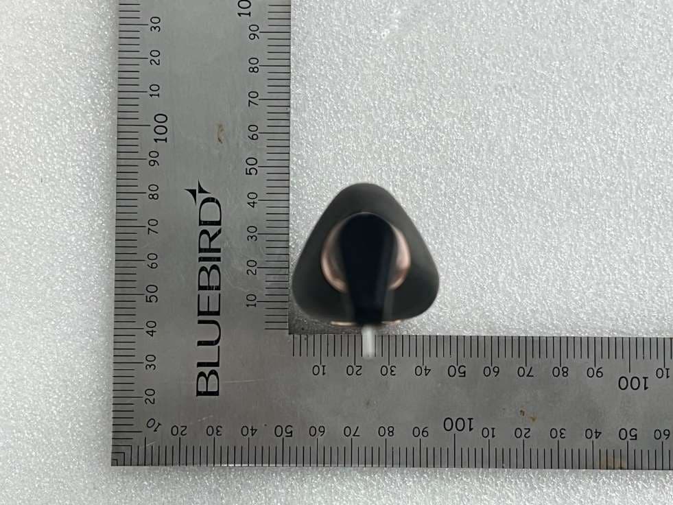
Click to zoom
Application Details
- Equipment Class
- DTS - Digital Transmission System
- Date of Grant
- Jan 24, 2023
- Application Purpose
- Original Equipment
- Date of Application
- Jan 24, 2023
- Equipment Note
- SmarTooth Dental Healthcare Device
- Frequency Range
- 2402.00000000 - 2480.00000000
- Company
- Smartooth Co.,Ltd.
- Country
- South Korea
Documents & Files
Document Text
Text extracted from the exhibit documents filed with the FCC. Open a document above to read the original.
Users Manual
Dental Monitoring Device STL-01-BK +82 02 518 2842 [email protected] https://smartooth.co/ Package Contents Package Functions ① Laser output ② Status LED ③ Power button ④ Measurement display LED ⑤ Battery holder cap · If any items are missing or damaged, please contact dealer. ① ② ③ ④ ⑤ Color ② Status LED ④ Measurement display LED Explanation Red Light Blinks green Blinks blue Red Light Yellow Light Green Light 20% or less of battery remaining Waiting for measurement Waiting for bluetooth connection Stage3 (Suspicion of caries) Stage2 (Needs care and attention) Stage1 (Normal) Smartooth body 1.5V AA Alkaline battery Base (Built-in Corrector in inner mirror) Disposable probe (6 pieces) Sold seperately × 6 Product Power Consumption Dimension · Model · Input · Weight SMARTOOTH 200mW 155.5 X 35.5 X 34.4(mm) W/O Probe STL-01-BK 1.5V 69.2g Installation & Synchronization Battery insertion & replacement Power On & Off 1) Remove the lid by turning it counterclockwise. 2) Insert the AA battery so that the (+) pole faces out. 3) Assemble the lid back by turning it clockwise. 1) To turn on the power, push the Power button for 1 second until beep sounds one time. 2) To turn off the power, push the Power button for 3 second until beep sounds one time. * If it is unused for more than 3 minutes, the power is turned off automatically. * When the Status LED displays red, please replace the battery since it means battery level is less than 20%. Probe Mount Attach the disposable Probe to the upper part of the body and fix it with the groove direction. Measurement may be affected if the probe is not mounted correctly. Application Installation 1) Access the Appstore. (Access the Play Store in case of Android) 2) Search for SmarTooth in the search bar and install the application. 1) Push the power button for 1 second to turn on the power. 2) Status LED blinks blue, which is remained until device and application are synchronized. 3) Run the application and log in. 4) When login is successful, the application scans and is synchronized with the device. 5) When synchronization is successful, the application screen changes as shown in the figure and the Status LED blinks green. Application Synchronization Calibration Quick Start Guide Measurement (Contact between teeth and device) Calibrating Insert the tip until it fully touches the bottom of the kit. 1) When you combine a probe into the body, please wait a moment for the device to recognize the atmosphere and press the ‘Next’ button for calibration. 2) Insert the sensor tip (the bottom side of the probe) vertically into the one of the three holes of the calibration kit inside the mirror. 3) When the sensor tip reaches the bottom of the calibration kit, press the ‘Next’ button again to obtain the calibrated reference. *Calibration may not be performed properly depending on the mounting condition of the probe. *If you calibrate once a sensor tip, the calibrated value remains when you turn off and on the device. Before you measure the tooth status, you need ‘calibration’, which is a set of adjustments performed on a sensor tip (probe) and device to make that SmarTooth function as accurately, or error free, as possible. 1) Click “Measure” button on application screen to start measurement. 2) After selecting tooth to be measured, position the tip perpendicular to the measurement surface, then the measurement value will be displayed on the screen. * Pressing or scratching with excessive force may damage teeth. * The number below the tooth picture in the center means the highest value and real-time value of the tooth measured currently. Measurement (To use application) 0-10 11-20 21-99 : teeth that is normal. : teeth that requires care and attention. : teeth that is suspicious of caries. * The measured value is not an absolute value for caries activity, but the higher value indicates the higher possibility of caries activity. * We recommend to visit a dentistry when you have any doubt about your tooth status, even if there is no pain. Stage 1 0 Stage 2 11 Stage 3 21 Interpretation of Measurement Values The measurement value ranges from 0 to 99. · Do not use the product for other purposes. · Do not stare directly into the laser. · Use leak-proof battery. · Remove the battery when the device is not used for a long time. · Do not use rechargeable battery. · Dispose the used battery according to regulation. · Do not change the battery with wet hands. · Do not use power supply. · Do not apply the voltage other than that specified on the product. · Do not use the probe for other purpose. · To check whether probe is mounted properly, pull the probe. · Do not bite tip sensor during measurement. · Excessive force to the tooth during measurement may break the tip. · Do not wash the product under running water or immerse it in water. ※ For more details, please refer to the pdf file of SmarTooth User Manual. Warning / Caution ! · Be careful not to apply strong impact. · Avoid exposure to heat, including prolonged exposure to direct sunlight. · Brush teeth before measuring for accurate measurement. · Use this product only for oral monitoring. · If the status LED is display red, replace the batteries. If the red light continues to blink without battery replacement, the device may be turned off during operation. · If multiple users share one device, use one probe per user. · The used probe should be disposed without washing to keep or reuse. · Do not disassemble the probe. · Keep the probe out of the reach of children. · The opened probe should be used immediately. · Do not disinfect probes and products. Note Important Safety Precautions ※ Please read the followings carefully and use the device correctly in order to prevent any damage to the user’s safety and property. ※ The revised User Manual does not contain the FCC required warning statements. a. Rule Part 15.19(a)(3): This device complies with part 15 of the FCC Rules. Operation is subject to the following two conditions: (1) …
Text truncated - open the document above for the full version.
Cover Letter(s)
Date: 04/17/2018 VCB_F-01: Operating Procedures Form – FCC Confidentiality v03 Page 1 of 1 Smartooth Co.,Ltd Space Salim #509, 10, Noryangjin-ro, Dongjak-gu, Seoul, Republic of Korea Federal Communications Commission Authorization and Evaluation Division Confidentiality Request regarding application for certification of FCC ID: 2A9XCSTL-01- BK Pursuant to Sections 0.457 and 0.459 of the Commission’s Rules, we hereby request confidential treatment of information accompanying this application as outlined below: Type of Confidentiality Requested Exhibit Type ☐Short Term ☒Permanent Block Diagrams ☒Short Term External Photos ☒Short Term ☐Permanent* Internal Photos ☐Short Term ☒Permanent Operation Description ☐Short Term ☒Permanent Parts List/BOM ☐Short Term ☒Permanent Schematics ☒Short Term Test Setup Photos ☒Short Term ☐Permanent* User manual *Requires further justification before permanent confidentiality will be allowed. The above materials contain trade secrets and proprietary information not customarily released to the public. The public disclosure of these materials may be harmful to the applicant and provide unjustified benefits to its competitors. Permanent Confidentiality: The applicant requests the exhibits listed above as permanently confidential be withheld from public review due to materials that contain trade secrets and proprietary information not customarily released to the public. Short-Term Confidentiality: Pursuant to DA04-1705 June 15, 2004 of the Commission’s public notice, we also request temporary confidential treatment of information accompanying this application as outlined below for an initial period of 180 (ie- “45”, “90” or “180”) days. Sincerely, Client’s signature: Client’s name & title: Ryou Myungseon /Executive Vice President Contact information / address: Smartooth Co.,Ltd
Cover Letter(s)
Smartooth Co.,Ltd Space Salim #509, 10, Noryangjin-ro, Dongjak-gu, Seoul, Republic of Korea Date: 04/17/2018 VCB_F-01: Operating Procedures Form – FCC Authorization v02 Page 1 of 1 Federal Communications Commission Authorization and Evaluation Division 1435 Oakland Mills Road Columbia, MD 21046 Date: January 10, 2023 SUBJECT: FCC Application for (FCC ID: 2A9XCSTL-01-BK) To Whom It May Concern: We, the undersigned, hereby authorize INCHUNG WORLD in Smartooth Co.,Ltd on our behalf, to apply to the Federal Communications Commission on our equipment. Any and all acts carried out by Smartooth Co.,Ltd on our behalf shall have the same effect as acts of our own. This is to advise that we are in full compliance with the Anti- Drug Abuse Act. We, the applicant, are not subject to a denial of federal benefits pursuant to Section 5301 of the Anti-Drug Act of 1988, 21 USC853a, and no party to the application is subject to a denial of federal benefits pursuant to that section. Sincerely, (Must be signed by the person that is listed on the FCC Website) Client’s signature: Client’s name & title: Ryou Myungseon /Executive Vice President Contact information / address: Smartooth Co.,Ltd
External Photos
External photo (Smartooth Co. Ltd_STL-01-BK (AT)) Front Rear External photo (Smartooth Co. Ltd_STL-01-BK (AT)) Left Right External photo (Smartooth Co. Ltd_STL-01-BK (AT)) Top Bottom
ID Label/Location Info
FCC ID: 2A9XCSTL-01-BK SAMPLE LABEL & LOCATION EUT Rear position Smartooth Co.,Ltd. Model : STL-01-BK (AT) Variant Model : STL-01-BK (GD) Rated Voltage : 1.5 V FCC ID : 2A9XCSTL-01-BK Made in Korea Copyright Ⓒ 2023, LTA Co., Ltd.
Internal Photos
Internal photo (Smartooth Co. Ltd_STL-01-BK (AT)) Inside Antenna Internal photo (Smartooth Co. Ltd_STL-01-BK (AT)) Main board_Top Main board_Bottom Internal photo (Smartooth Co. Ltd_STL-01-BK (AT)) Sub board_Top Sub board_Bottom
RF Exposure Info
FCC ID: 2A9XCSTL-01-BK ATTACHMENT RF EXPOSURE EVULATION 1.1 Limit According to §1.1310 and §2.1091 RF exposure is calculated. (B) Limits for General Population/Uncontrolled Exposures Frequency range (MHz) Electric field Strength Magnetic field Strength Power density Averaging time 1.34 - 30....................................... 824/f 2.19/f *(180/ f²) 30 30 - 300....................................... 27.5 0.073 0.2 30 300 - 1500.................................... ............... ............... f/1500 30 1500 - 100.000................................. ............... ............... 1.0 30 F = frequency in MHz * = Plane-wave equivalent power density 1.2 MAXIMUM PERMISSIBLE EXPOSURE Prediction Prediction of MPE limit at a given distance Power density at the specific separation: S = PG/(4R 2 π) Where, S = Maximum power density (mW/cm 2 ) P = Power input to the antenna (mW) G = Numeric power gain of the antenna R = Distance to the center of the radiation of the antenna (20 cm = limit for MPE) S = (0.11 * 1.70) / (4 * 5 2 * π) S = 0.06 mW/cm 2 FCC ID: 2A9XCSTL-01-BK ATTACHMENT 1.3 MAXIMUM PERMISSIBLE EXPOSURE Prediction - Calculated under the worst-case conditions of each mode. (Measured power -10 dBm ± 0.5dB) 3-1. 2.4 GHz Mode Max Peak output Power at antenna input terminal -9.56 dBm Max Peak output Power at antenna input terminal 0.11 mW Prediction distance 5 mm Prediction frequency 2402 MHz Antenna Gain(typical) 2.3 dBi Antenna Gain(numeric) 1.70 - Power density at prediction frequency( S) 0.06 mW/cm 2 MPE limit for uncontrolled exposure at prediction frequency 0.03 mW/cm 2 SAR Test exclusion thresholds for 100MHz to 6GHz at test separation distance ≤ 50 mm = Used [(max.power of channel, including tune-up torelance, mW)/(min. test separation distance, mm)] * [√f(GHz)] = [0.11 / 5 ] * [ √2.402 ] = 0.003 ≤ 3.0, for 1g SAR Thus, SAR for this device is not required.
Test Report
Ref. No.: LR500112301A 243 Jubug-Ri,Yangji-Myeon, Yongin-Si, Gyeonggi-Do, Korea 17159 Tel: +82-31-323-6008 Fax: +82-31-323-6010 http://www.ltalab.com Dates of Tests: January 02 ,2023 ~ January 04 ,2023 Test Report S/N: LR500112301A Test Site : LTA CO., LTD. CERTIFICATION OF COMPLIANCE FCC ID. APPLICANT Equipment Class : Digital Transmission System (DTS) Manufacturing Description : SmarTooth Dental Healthcare Device Manufacturer : Smartooth Co.,Ltd Model name : STL-01-BK ( AT ) Variant Model name : STL-01-BK (GD) Test Device Serial No.: : Identical prototype Rule Part(s) : FCC Part 15.247 Subpart C ; ANSI C63.10 - 2013 Frequency Range : 2402 ~ 2480 MHz BLE Max. Output Power : Max -9.56 dBm - Conducted Data of issue : January 05 ,2023 This test report is issued under the authority of: The test was supervised by: Ja-Beom Koo, Manager Eun-Hwan Jung, Test Engineer This test result only responds to the tested sample. It is not allowed to copy this report even partly without the allowance of the test laboratory. The report must not be used by the client to claim product certification, approval, or endorsement by NVLAP, NIST, or any agency of the Federal Government. NVLAP LAB Code.: 200723-0 2A9XCSTL-01-BK Smartooth Co.,Ltd Copyright ○ c 2021, LTA Co., Ltd. Page 1 of 29 Ref. No.: LR500112301A TABLE OF CONTENTS 1. GENERAL INFORMATION -------------------------------------------------------------------------- 2. INFORMATION ABOUT TEST ITEM ------------------------------------------------------------- 3. TEST REPORT ------------------------------------------------------------------------------------------ 3.1 SUMMARY OF TESTS ---------------------------------------------------------------------------- 3.2 TECHNICAL CHARACTERISTICS TEST ---------------------------------------------------- 3.2.1 6 dB BANDWIDTH -------------------------------------------------------------------------- 3.2.2 PEAK OUTPUT POWER -------------------------------------------------------------------- 3.2.3 POWER SPECTRAL DENSITY ------------------------------------------------------------ 3.2.4 BAND EDGE ---------------------------------------------------------------------------------- 3.2.5 CONDUCTED SPURIOUS EMISSIONS ------------------------------------------------- 3.2.6 RADIATED SPURIOUS EMISSIONS ---------------------------------------------------- APPENDIX APPENDIX TEST EQUIPMENT USED FOR TESTS -------------------------------------------- 3 4 5 5 6 6 8 10 12 14 16 29 Copyright ○ c 2021, LTA Co., Ltd. Page 2 of 29 Ref. No.: LR500112301A 1. General information 1- 1 Test Performed Company name : LTA Co., Ltd. Address : 243, Jubug-ri,Yangji-Myeon,Youngin-Si, Kyunggi-Do, Korea. 17159 Web site : http://www.ltalab.com E-mail : [email protected] Telephone : +82-31-323-6008 Facsimile +82-31-323-6010 Quality control in the testing laboratory is implemented as per ISO/IEC 17025 which is the “General requirements for the competents of calibration and testing laboratory”. 1- 2 Accredited agencies LTA Co., Ltd. is approved to perform EMC testing by the following agencies: Agency Country Accreditation No. Validity Reference NVLAP U.S.A 200723-0 2023-09-28 ECT accredited Lab. RRA KOREA KR0049 - EMC accredited Lab. FCC U.S.A 649054 2023-01-25 FCC CAB VCCI JAPAN C-4948, 2023-09-10 VCCI registration VCCI JAPAN T-2416, 2023-09-10 VCCI registration VCCI JAPAN R-4483(10 m), 2023-08-15 VCCI registration VCCI JAPAN G-847 2023-12-13 VCCI registration IC CANADA 5799A-1 2023-10-18 IC filing Copyright ○ c 2021, LTA Co., Ltd. Page 3 of 29 Ref. No.: LR500112301A 2. Information about test item 2-1 Client & Manufacturer Client Company name : Smartooth Co.,Ltd Address : Space Salim #509, 10, Noryangjin-ro, Dongjak-gu, Seoul, Republic of Korea Tel / Fax : +82-10-2645-9879 / +82-31-8015-6465 Manufacturer Smartooth Co.,Ltd Address Space Salim #509, 10, Noryangjin-ro, Dongjak-gu, Seoul, Republic of Korea Tel / Fax +82-10-2645-9879 / +82-31-8015-6465 2- 2 Equipment Under Test (EUT) Model name : STL-01-BK (AT) Serial number : Identical prototype Date of receipt : January 02, 2023 EUT condition : Pre-production, not damaged Antenna type : Chip Antenna (Max Gain : 2.3 dBi) Frequency Range : 2402 ~ 2480 MHz BLE RF output power : Max -9.56 dBm – Conducted Type of Modulation : GFSK Power Source : DC 1.5 V 2- 3 Tested frequency LOW MID HIGH Frequency (MHz) 2402 2442 2480 2-4 Ancillary Equipment Equipment Model No. Serial No. Manufacturer Notebook - MS-1736 MSI Copyright ○ c 2021, LTA Co., Ltd. Page 4 of 29 Ref. No.: LR500112301A 3. Test Report 3.1 Summary of tests FCC Part Section(s) Parameter Test Condition Status (note 1) 15.247(a) 6 dB Bandwidth Conducted C 15.247(b) Transmitter Peak Output Power C 15.247(e) Transmitter Power Spectral Density C 15.247(d) Band Edge & Conducted Spurious emission C 15.209 Transmitter emission Radiated C 15.207 AC Conducted Emissions Conducted N/A 15.203 Antenna requirement - C N/A : This product is only operated with DC voltage. The above equipment was tested by LTA Co., Ltd. The test data, data evaluation, test procedures, and equipment configurations shown in this report were made in accordance with the procedures given in ANSI C63.10-2013 and the energy emitted by the sample EUT tested as described in this report is in compliance with the requirements of FCC Rules Part 2 and Part 15.247 The test results of this report relate only to the tested sample identified in this report. The tests were performed according to the method of measurements prescribed in KDB No.558074. Antenna Requirement Smartooth Co.,Ltd FCC ID: 2A9XCSTL-01-BK unit complies with the requirement of §15.203. The antenna type is Chip Antenna Copyright ○ c 2021, LTA Co., Ltd. Page 5 of 29 Ref. No.: LR500112301A 3.2 Technical Characteristics Test 3.2.1 6 dB Bandwidth Procedure: The bandwidth at 6 dB below the highest in-band spectral density was measured with a spectrum analyzer connected to the antenna terminal, while EUT is operating in transmission mode at the…
Text truncated - open the document above for the full version.
Test Report
Application Bluetooth Zigbee WLAN (IEEE 802.11 b/g) ISM 2.4GHz Wireless Devices Features Helical Structure Small Size (3.2*1.6*1.2mm 3 ) Easy Optimizing with external lumped matching components SMT Available under Pb-free Condition RoHSCompliant DATASHEET DocumentDatasheet TypeMultilayer Chip Antenna Application2.4GHz Part No.ALA321C3 Revision7.0 Notes The contents of this datasheet are subject to change without notice. Please confirm the specifications and delivery conditions when placing your order. AMOTECH AMOTECH Co., Ltd. Datasheet / Multilayer Chip Antenna / 2.4GHz ALA321C3 (Rev 7.0) 2 Rev. NoDateTitleContentsPage 7’09.04.07FormatChangeddocument format Table of Content Revision History 1.Specifications 3 1.1 Electrical Specifications 3 1.2 Mechanical Specifications 3 1.3 Appearance and Material 3 2. PCB Design for Test 4 2.1 Evaluation BoardDimension 4 2.2 PCB Design Guide 4 3. Measurement Result 5 3.1 Typical Measurement Result (VSWR/RL,Smithchart) 5 3.2 Typical Measurement Result(Gain, Radiation Pattern) 6 4. Reliability 7 5. Soldering Reflow Profile 7 6. Packaging 8 6.1 Carrier Tape Dimension 8 6.2 PackagingQuantity 8 6.3 Packaging Label 8 Datasheet / Multilayer Chip Antenna / 2.4GHz ALA321C3 (Rev 7.0) 3 NoItemSpec.Remark 1Frequency Range [GHz]2.4 ~2.485 2VSWRMax 3.0:1 3Peak Gain [dBi]typ. 2.3 4Total Avg. Gain [dBi]typ. -0.6 5Efficiency [%]typ. 84 6PolarizationLinear 7Impedance [Ω]Nominal 50 The results are measured on the 10x43mm 2 evaluation board(EVB). See Page 6. for more detail gain parameter NoItemSpec.Remark 1Dimensions (LxWxH)3.2x1.6x1.2 mm 3 2Unit Weighttyp. 20 mg 3Operating Temperature-35 ~ +85 °C 1.1 Electrical Specifications 1.2 Mechanical Specifications NoItemFunctionMaterial ①External ElectrodeSoldering, Input PortAg/Ni/Sn ② Direction indexIndication of Ceramic ③Ceramic Body-Ceramic ④Model No. index-Ceramic ⑤External ElectrodeSolderingAg/Ni/Sn 1.3 Appearance & Material 1. Specifications ⑤ ④ ③ ② ① 0.4±0.2 3.2±0.3 1.6±0.2 Side 1.2±0.2 (unit : mm) A3 Datasheet / Multilayer Chip Antenna / 2.4GHz ALA321C3 (Rev 7.0) 4 2.1 Evaluation Board Dimension 2.2 PCB Design Guide 2. PCB Design for Test Matching Component [unit : mm] Evaluation board size ~ 10x43 Fill Cut Area (GND Clearance) ~ 10x13 [PCB Solder Land] Chip Antenna Matching Stage SMA Connector GND [Unit : mm] 4.0 0.8 1.8 2.4 50 Ohm Feeding Line NoPin Assignment ① Feeding ②N.C ① ② Datasheet / Multilayer Chip Antenna / 2.4GHz ALA321C3 (Rev 7.0) 5 3.1 Typical Measurement Result (VSWR/RL, Smithchart) 3. Measurement Result The results are measured on the 10x43mm 2 evaluation board(EVB). NoMatching Value ①N.C ②5.6 nH ③ 1.8 nH ③① ② Datasheet / Multilayer Chip Antenna / 2.4GHz ALA321C3 (Rev 7.0) 6 [Azimuth plane @2.45GHz ] [Elevation1 plane @2.45GHz ] [Elevation2 plane @2.45GHz ] [3D Radiation Pattern] 3.2 Typical Measurement Result (Gain, Radiation Pattern) x y z -y Azimuth E1 E2 Peak Gain (dBi) Avg. Gain (dBi) Total Avg. Gain (dBi) Efficiency (%) Azimuth 2.0-0.2 -0.684 Elevation 1 2.3-1.8 Elevation 2 0.9-2.7 Datasheet / Multilayer Chip Antenna / 2.4GHz ALA321C3 (Rev 7.0) 7 NoItemTest ConditionTest Requirements 1 Adhesive Strength of Termination 1.Applied force on SMT chip till detached point from PCB. 1. No mechanical damage by applied force 2. Strength (F) > 3 kgf 2 Thermal Shock (Cycle) 1. Step 1 : -40 ±3°C, 30 min Step 2 : +125 ±3°C, 30 min 2. Number of cycle : 30 1. No visual damage 2. Within electric spec (VSWR) 3 High Temperature Resistance 1. Temperature : +125 ±5°C 2. Time : 1000 ±24 hrs 1. No visual damage 2. Within electric spec (VSWR) 4 Low Temperature Resistance 1. Temperature : -40 ±5°C 2. Time : 1000 ±24 hrs 1. No visual damage 2. Within electric spec (VSWR) 5Humidity 1. Humidity : 85 % RH Temperature : +85 ±3°C 2. Time : 1000 ±24 hrs 1. No visual damage 2. Within electric spec (VSWR) F SMD PAD PCB 4. Reliability 5. Soldering Reflow Profile Datasheet / Multilayer Chip Antenna / 2.4GHz ALA321C3 (Rev 7.0) 8 ItemSpec.ItemSpec.ItemSpec. A01.90±0.10P04.00 ±0.10E1.75±0.10 B03.50±0.10P14.00 ±0.10F7.50±0.10 K01.50±0.10P22.00 ±0.10W16.00±0.30 D01.55±0.05--t0.30±0.05 Item QuantityDimension Reel2,000eaΦ7” * 12mm Inner Box6,000ea (3 reel)185 * 185 * 68 (mm 3 ) Outer Box130,000ea (5 Inner Box)375 * 200 * 205 (mm 3 ) Outer Box260,000ea (10 Inner Box)390 * 375 * 205 (mm 3 ) 6.1 Carrier Tape Dimension 6.2 Packaging Quantity 6.3 Packaging Label 6. Packaging AMOTECH Co., Ltd. 5BL-1Lot, 617, Namchon-Dong, Namdong-Gu, Incheon, Korea Multilayer Chip Antenna P/N : ALA321C3 Lot No : Quantity : 2,000 pcs Date : 2010/01/19
Contact Information
Applicant
Ryou Myungseon
Test Firm
LTA Co.,LtdAhn Chulho
Technical Specifications
| # | Rule Parts | Frequency Range | Power Output |
|---|---|---|---|
| 1 | 15C | 2.40 GHz - 2.48 GHz | 100.00 µW |