2AA2K-UDV888ULTRA-DV with 802.11b/g
CANSONIC INC.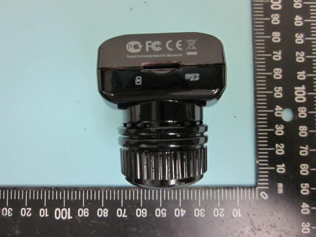
Click to zoom
Application Details
- Equipment Class
- DTS - Digital Transmission System
- Date of Grant
- Sep 22, 2014
- Application Purpose
- Original Equipment
- Date of Application
- Sep 22, 2014
- Equipment Note
- ULTRA-DV with 802.11b/g
- Frequency Range
- 2412.00000000 - 2462.00000000
- Company
- CANSONIC INC.
- Country
- Taiwan
Documents & Files
Document Text
Text extracted from the exhibit documents filed with the FCC. Open a document above to read the original.
Users Manual
Warning notice The Federal Communication Commission Statement This equipment has been tested and found to comply with the limits for a Class B Digital Device, pursuant to Part 15 of the FCC rules. These limits are designed to provide reasonable protection against harmful interference in a residential. This equipment generates, uses and can radiate radio frequency energy and , if not installed and used in accordance with the instruction, may cause harmful interference to radio communication. However, there is no guarantee that interference to radio or television reception, which can be determined by turning the equipment off and on, the user is encouraged to try to correct the interference by one of more of the following measures: * Reorient or relocate the receiving antenna. * Increase the separation between the equipment and receiver. * Connect the equipment into an outlet on a circuit different from that to which the receiver is connected. * Consult the dealer or an experienced Radio/TV technician for help. Use only shielded cables to connect I/O devices to this equipment. You are cautioned that change or modifications not expressly approved by the party responsible for compliance could void your authority to operate the equipment. THIS DEVICE COMPLIES WITH PART 15 OF FCC RULES. OPERATION IS SUBJECT TO THE FOLLOWING TWO CONDITIONS: 1. This device may not cause harmful interference and 2. This device must accept any interference received, including interference that may cause undesired operation. The antenna used for this transmitter must not be collocated or operation in conjunction with any other antenna or transmitter. Notice : The changes or modifications not expressly approved by the party responsible for compliance could void the user’s authority to operate the equipment. IMPORTANT NOTE: To comply with the FCC RF exposure compliance requirements, no change to the antenna or the device is permitted. Any change to the antenna or the device could result in the device exceeding the RF exposure requirements and void user’s authority to operate the device. Features...................................................................................1 Notice......................................................................................3 About this manual......................................................................4 Know the product.......................................................................5 Cansonic cap installment ...........................................................6 Car bracket mount .....................................................................6 Start using this product ..............................................................7 Battery charging .......................................................................7 Inserting the microSD card.........................................................7 Powering ON/OFF.....................................................................8 Basic operation.........................................................................9 Switching between modes..........................................................9 Video......................................................................................10 Operation of the emergency storage function..............................10 Muting function........................................................................10 Application of 3G G sensor function...........................................10 Application of GPS function(option)..........................................10 WiFi function............................................................................11 Time-lapse function..................................................................11 Real-time surveillance application.............................................11 Video settings.........................................................................12 Photo.....................................................................................12 photo settings.........................................................................12 Playback mode.......................................................................13 Playback settings....................................................................13 Usage mode of AP player(option)..............................................14 TV connection.........................................................................16 AV OUT (option)......................................................................16 HDMI OUT (option)..................................................................16 PC connection........................................................................17 Reset system..........................................................................17 WiFi manual(Android)..............................................................18 WiFi manual(iOS)....................................................................25 Specification...........................................................................31 Accessories............................................................................32 Contents Features This is the latest product of ultra-small size and powerful FULL HD ULTRA digital video recorder. 140 degrees A+ level high resolution extra wide angle lens with high quality and high dynamic photosensitive element. It improves the night vision capability to catch the clear pictures in the dark environment. It also has anti-shock function to prevent the pictures dimming from shaking. Our company original and breakthrough parking collision detection function. When your car is vibrated by external vibration under the parking situation, it will automatically start and recording one minute and then automatically turn off. After the UDV-888 turn off, it won’t consume the electricity, so the battery can be used longer. With the automatic recording function when the car turn on, and automatic turn off for delay of 30…
Text truncated - open the document above for the full version.
Users Manual
1. Video Click the video in video area to play , then click the play button to watch the corresponding video in the video play area; if the computer is connected to the Internet, corresponding track can be displayed in electronic map area (on condition that corresponding GPS longitude and latitude has been recorded); if the G-Sensor value is recorded in this machine, the curve of gravity change of 3 axes will be displayed in G-Sensor area, so as to detect the driving stability and see whether there is crash or hard braking, etc. (underway). 2. Photo Click the photo in photo area to play the photo will be displayed in picture play area; if the computer is connected to the Internet, shooting location of the photo can be displayed in electronic map area. TV connection AV OUT (option) Connect the AV OUT cable as below. HDMI OUT (option) Connect the HDMI OUT cable as below. 16 Connect the USB cable to PC, and UDV-888 will show three kinds of interface. USB mode: to manage the files in the SD card. PC cam mode: PC cam interface. Work mode: Recorder by using PC power. PC connection Reset system Note: If the device stop working by inappropriate operation, please press reset key to restart the device. 17 OK Cansonic UDV-888_1xxxxxx 88888888 MENU Enter Back WiFi manual(Android) App setup Please login Google market then download and setup CANSONIC Ultradv APP. After installing will add the icon in the application. WiFi connection 1) Open the WiFi function of the smart-device. 2) Open the WiFi function of the UDV-888. Please enter into setup mode of UDV-888, and then enter the selection "WiFi Password". The device number cannot be modified, the default password is 8888 8888. To protect the privacy, cansonic recommend setup your own password. Password modified: left/right select the order, up/down select the number, press ok to keep your settings. Enter your password to connect with smart-device. Under the preview mode, press the DOWN button will start the WiFi function, and the screen will display means " Waiting for WiFi Connection" . 3).After start the WiFi function of the UDV-888, the smart-device will synchronous search the WiFi signal named as the SSID of CANSONIC UDVxxxxxx, and click to connect. Enter the password number to first connection, testify the password is correct will search the IP address and connect.After finishing connecting, the smart-device will display . 4). Touch the APP on the smart-device will display means “WiFi Connection Working” and enter the video mode. THE DEFAULT PASSWORD IS 8888 8888. 18 Open the App will enter the video mode, and will display the video resolution WIFI signal reception, battery life, and white balance and so on. Video mode Resolution White Balance Settings Album Photo/ Video Mode Battery life WiFi Signal Video Touch the record icon will start recording, and the red point will flicker; the panel of the UDV-888 will display means “Video Recording”. Video WiFi Signal According to different WiFi signal receptions, display different icon. Battery Life Show the battery life to remind the user. Touch the record icon will stop recording the video, and the red point will stop flickering; It’s will return the preview mode, the icon will disappear and the panel of the UDV-888 will display means “WiFi Connection Ready!” 19 Video Resolution Touch the icon to set up the resolution. FHD 1080P resolution is 1920x1080P 30FPS HD 720P 60FPS resolution is 1280x720P 60FPS HD 720P 30FPS resolution is 1280x720P 30FPS Settings Touch the icon to setup mode. Mode switching Touch the icon will switch to Photo mode, Touch the icon will return to Video mode. Photo mode Touch the icon will switch to Photo mode, and it would display self-timer setting, resolution, WiFi signal reception, battery life, white balance and so on. Self-timer Resolution White Balance Settings WiFi signal Battery life Album Photo/Video mode Photo 20 Capture Photo Touch the icon to take a photo. WiFi signal reception According to different WiFi signal receptions, display different icon. Battery Life Show the battery life to remind the user. Self-timer Touch the icon to set up the time as below. Select off, it would not count down. Select 2s, it would count down 2 seconds. Select 10s, it would count down 10 seconds. Resolution Touch the icon to select the resolution as below. The number of remaining pictures would change by different resolution. 10M=3646X2736 8M=3264X2448 6M=2816X2112 3M=2048X1536 2M=1920X1080 VGA=640X480 Setting Touch the setup icon will display the setup interface as video mode . Mode switching Touch the video icon will switch to the video mode, and touch the photo icon will switch to the photo mode. 21 Setup mode Touch the icon to setup mode. Option name Function White balance Auto, Daylight, Cloudy, Tungsten, Fluor H Frequency 50Hz/60Hz Format Format the SD card of the UDV-888, please backup the file before formatting. App Version Display the App version. Product Name CANSONIC UDV-888 FW Version Display the Firmware Version. Album mode Touch the icon will enter into Album mode, at the same time, the panel of the UDV-888 would become black and display , and the smart-device would display as below. 22 Fast Download Touch the icon to download all the pictures and videos on the SD card of the UDV-888. File View Touch a file will enter into "single file playback mode" . Touch the as above, it will download all the files of the SD card. Touch the arrow icon and to select next and last file to display. At this moment, the file will download to the smart-device, if the file is so big, please be patient to wait for data transmission. The video file cannot be played back yet, please download to the smart-device to playback. File Download a. In "single file playback mode", touch the icon will pop up the information to /mnt/sdcard/DCIM; b. Under the multi file preview mode, touch the icon will enter the interface of the multi-file selection. If want to download one file, select and touch the file y…
Text truncated - open the document above for the full version.
Cover Letter(s)
CANSONIC INC. 10F., No. 359, Dehe Rd., Yonghe Dist., New Taipei City 234, Taiwan R.O.C. Tel: 886-2-2929-0321 Fax: 886-2-2927-3401 Declaration of Conformity Date: SEP. 15, 2014 BABT TCB Forsyth House, Churchfield Road, Walton-on-Thames, Surrey, KT12 2TD Confidentiality Request FCC ID: 2AA2K-UDV888 Pursuant to Sections 0.457(d)(1)(ii) and 0.459 of the Commission’s Rules, Trend Electronics Co., Ltd. here by requests permanent confidential treatment of information accompanying this application as outlined below: Schematics Block Diagrams Description of Operation The above materials contain trade secrets and proprietary information not customarily released to the public. The public disclosure of these matters might be harmful to the Applicant and provide unjustified benefits to its competitors. The Applicant understands that pursuant to Rule 0.457(d)(1)(ii), disclosure of this Application and all accompanying materials will not be made before the date of the Grant for this Application. Yours sincerely, Company Officer Luke Hsu / PM Telephone Number: +886-2-2929-0321 E-Mail: [email protected] / [email protected]
Cover Letter(s)
CANSONIC INC. 10F., No. 359, Dehe Rd., Yonghe Dist., New Taipei City 234, Taiwan R.O.C. Tel: 886-2-2929-0321 Fax: 886-2-2927-3401 DOC Letter SEP. 18, 2014 BABT TCB Forsyth House, Churchfield Road, Walton-on-Thames, Surrey, KT12 2TD Dear Regulatory Authority, We, the undersigned, hereby declare that FCC Part 15B Declaration of Conformity procedures will be applied to the digital device portion of the following product: Product: ULTRA-DV Model: UDV-888 FCC Part 15B DoC report number: F13092302 This Device complies with Part 15B DoC of the FCC rules, operation is subject to the following two conditions. This device may not cause harmful interference and, This device must accept any interference received, Including interference that may cause undesired operation TEST LABORATORY PEP Certification Corp. 12F.-3, No.27-1, Ln. 169, Kangning St., Xizhi Dist., New Taipei City 221, Taiwan (R.O.C.) Accredited Lab. Assigned under FCC number: TW1075 Sincerely, CANSONIC INC. 10F., No. 359, Dehe Rd., Yonghe Dist., New Taipei City 234, Taiwan R.O.C.
External Photos
ETC Report No. : 14-09-RBF-004 FCC ID: 2AA2K-UDV888 Sheet 1 of 11 Sheets Rev. No 2.1 CONSTRUCTION PHOTOS OF EUT 1. 2. ETC Report No. : 14-09-RBF-004 FCC ID: 2AA2K-UDV888 Sheet 2 of 11 Sheets Rev. No 2.1 CONSTRUCTION PHOTOS OF EUT 3. 4. ETC Report No. : 14-09-RBF-004 FCC ID: 2AA2K-UDV888 Sheet 3 of 11 Sheets Rev. No 2.1 CONSTRUCTION PHOTOS OF EUT 5. 6.
ID Label/Location Info
Label location This device complies with Part 15 of the FCC Rules. Operation is subject to the following two conditions: (1) this device may not cause harmful interference, and (2) this device must accept any interference received, including interference that may cause undesired operation. FCCID : 2AA2K-UDV888
Internal Photos
ETC Report No. : 14-09-RBF-004 FCC ID: 2AA2K-UDV888 Sheet 4 of 11 Sheets Rev. No 2.1 CONSTRUCTION PHOTOS OF EUT 7. 8. ETC Report No. : 14-09-RBF-004 FCC ID: 2AA2K-UDV888 Sheet 5 of 11 Sheets Rev. No 2.1 CONSTRUCTION PHOTOS OF EUT 9. 10. DC Power Cord ETC Report No. : 14-09-RBF-004 FCC ID: 2AA2K-UDV888 Sheet 6 of 11 Sheets Rev. No 2.1 CONSTRUCTION PHOTOS OF EUT 11. HDMI Cable 12. ETC Report No. : 14-09-RBF-004 FCC ID: 2AA2K-UDV888 Sheet 7 of 11 Sheets Rev. No 2.1 CONSTRUCTION PHOTOS OF EUT 13. 14. ETC Report No. : 14-09-RBF-004 FCC ID: 2AA2K-UDV888 Sheet 8 of 11 Sheets Rev. No 2.1 CONSTRUCTION PHOTOS OF EUT 15. 16. ETC Report No. : 14-09-RBF-004 FCC ID: 2AA2K-UDV888 Sheet 9 of 11 Sheets Rev. No 2.1 CONSTRUCTION PHOTOS OF EUT 17. 18. ETC Report No. : 14-09-RBF-004 FCC ID: 2AA2K-UDV888 Sheet 10 of 11 Sheets Rev. No 2.1 CONSTRUCTION PHOTOS OF EUT 19. 20. ETC Report No. : 14-09-RBF-004 FCC ID: 2AA2K-UDV888 Sheet 11 of 11 Sheets Rev. No 2.1 CONSTRUCTION PHOTOS OF EUT 21.
RF Exposure Info
Page No. : 1 of 2 Maximum Permissible Exposure (MPE) The modular use shall be at least 20cm distance away from human body. MPE Calculation Method: E(V/m) = √ ଷ ୶ ୶ ୋ ୢ Power Density = Pd(mW/cm 2 ) = మ ଷ Combine these two formulas can be changed to: Pd = ଷ ୶ ୶ ୋ ଷ ୶ ୢ మ Note: 1. “E” means Electric field (V/m) 2. “P” means Peak RF output power (W) 3. “G” means EUT Antenna numeric gain (numeric) 4. “d” means the minimum mobile separation distance is 0.2m between radiator and human body. Page No. : 2 of 2 Antenna Gain Antenna Gain: The maximum Gain is 0.44 dBi. ANT Modulation Type Channel Frequency (MHz) Output Power to Antenna (dBm) Power Density (mW/cm 2 ) Limit of Power Density (mW/cm 2 ) 802.11b 01 2412 16.5 0.0039 < 1 06 2437 17.6 0.0050 11 2462 17.8 0.0053 802.11g 01 2412 14.2 0.0023 < 1 06 2437 15.4 0.0030 11 2462 15.9 0.0034
Test Report
Rev. No 2.0 FCC Part 15 EMI TEST REPORT of E.U.T. : ULTRA-DV Model No. : UDV-888 FCC ID. : 2AA2K-UDV888 for APPLICANT : CANSONIC INC. ADDRESS : 10F., No. 359, Dehe Rd., Yonghe Dist., New Taipei City 234,Taiwan R.O.C. Test Performed by ELECTRONICS TESTING CENTER, TAIWAN NO. 34. LIN 5, DINGFU VIL., LINKOU DIST., NEW TAIPEI CITY, TAIWAN, 24442, R.O.C Tel : (02)26023052 Fax : (02)26010910 http://www.etc.org.tw ; e-mail: [email protected] Report Number : 14-09-RBF-004 ETC Report No. : 14-09-RBF-004 FCC ID: 2AA2K-UDV888 Rev. No 1.0 TEST REPORT CERTIFICATION Applicant : CANSONIC INC. 10F., No. 359, Dehe Rd., Yonghe Dist., New Taipei City 234, Taiwan R.O.C. Manufacturer : FOCUSCO INC. 3F, Building 2, 4 .th District Foodstuff Group Industrial Zone HuanGuan Road, Guanluan, Shenzhen Guang Dong China Description of EUT a) Type of EUT : : : : ULTRA-DV b) Trade Name CANSONIC c) Model No. UDV-888 d) Power Supply Battery 3.7V ,2.95Wh, 800mAh Regulation Applied : FCC Rules and Regulations Part 15 Subpart C I HEREBY CERTIFY THAT: The data shown in this report were made in accordance with the procedures given in ANSI C63.4, and the energy emitted by the device was founded to be within the limits applicable. I assume full responsibility for accuracy and completeness of these data. Note: 1. The result of the testing report relate only to the item tested. 2. The testing report shall not be reproduced expect in full, without the written approval of ETC. Summary of Tests Test Results Radiated Emission Pass Conducted Emission N/A Emission Bandwidth Pass Output Power Pass 100 kHz Bandwidth of Band Edges Pass Power Density Pass Out-of-Band Conducted Emission Pass ETC Report No. : 14-09-RBF-004 FCC ID: 2AA2K-UDV888 Rev. No 1.0 Date Test Item Received : Sep. 05, 2014 Date Test Campaign Completed : Sep. 11 , 2014 Date of Issue : Sep. 12 , 2014 Test Engineer : ( Jiapeng Chen, Engineer ) Approve & Authorized : S. S. Liou, Section Manager EMC Dept. II of ELECTRONICS TESTING CENTER, TAIWAN ETC Report No. : 14-09-RBF-004 FCC ID: 2AA2K-UDV888 Rev. No 1.0 Table of Contents Page 1 GENERAL INFORMATION ....................................................................................................... 1 1.1 Product Description ...................................................................................................................... 1 1.2 Characteristics of Device ............................................................................................................. 1 1.3 Test Methodology ........................................................................................................................ 1 1.4 Test Facility .................................................................................................................................. 1 2 PROVISIONS APPLICABLE ...................................................................................................... 2 2.1 Definition ..................................................................................................................................... 2 2.2 Requirement for Compliance ....................................................................................................... 3 2.3 Restricted Bands of Operation ..................................................................................................... 5 2.4 Labeling Requirement .................................................................................................................. 5 2.5 User Information .......................................................................................................................... 6 3. SYSTEM TEST CONFIGURATION .......................................................................................... 7 3.1 Justification .................................................................................................................................. 7 3.2 Devices for Tested System ........................................................................................................... 7 4 RADIATED EMISSION MEASUREMENT .............................................................................. 8 4.1 Applicable Standard ..................................................................................................................... 8 4.2 Measurement Procedure ............................................................................................................... 8 4.3 Measuring Instrument ................................................................................................................ 10 4.4 Radiated Emission Data ............................................................................................................. 11 4.5 Field Strength Calculation ......................................................................................................... 21 4.6 Photos of Radiation Measuring Setup ........................................................................................ 22 5 CONDUCTED EMISSION MEASUREMENT ........................................................................ 23 5.1 Standard Applicable ................................................................................................................... 23 6 ANTENNA REQUIREMENT .................................................................................................... 24 6.1 Standard Applicable ................................................................................................................... 24 6.2 Antenna Construction and Directional Gain .............................................................................. 24 7 EMISSION BANDWIDTH MEASUREMENT ........................................................................ 25 7.1 Standard Applicable ................................................................................................................... 25 7.2 Measurement Procedure ..................................................................................…
Text truncated - open the document above for the full version.
Test Setup Photos
ETC Report No. : 14-09-RBF-004 FCC ID: 2AA2K-UDV888 Sheet 22 of 56 Sheets Rev. No 2.0 4.6 Photos of Radiation Measuring Setup
Contact Information
Applicant
Luke Hsu
Test Firm
Taiwan Testing and Certification CenterAnderson Ku
Technical Specifications
| # | Rule Parts | Frequency Range | Power Output |
|---|---|---|---|
| 2 | 15C | 2.41 GHz - 2.46 GHz | 38.91 mW |
Other Applications from CANSONIC INC.

2AA2K-Z4C
Feb 10, 2026Dash cam
Equipment Class
NII - Unlicensed National Information Infrastructure TX
2AA2K-S3
Feb 14, 2023Dash cam
Equipment Class
DTS - Digital Transmission System
2AA2K-Z3SC
Feb 13, 2023Dash cam
Equipment Class
DTS - Digital Transmission System