2AA2QFP1V1Mobile Phone
Fairphone B.V.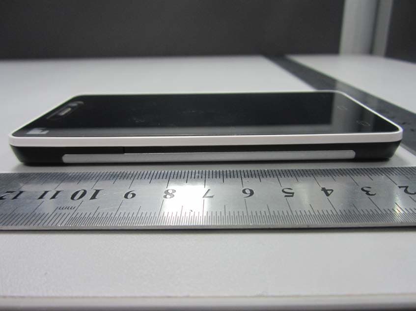
Click to zoom
Application Details
- Equipment Class
- PCE - PCS Licensed Transmitter held to ear
- Date of Grant
- Nov 25, 2013
- Application Purpose
- Original Equipment
- Date of Application
- Nov 25, 2013
- Equipment Note
- Mobile Phone
- Frequency Range
- 1850.20000000 - 1909.80000000
- Company
- Fairphone B.V.
- Country
- Netherlands
Documents & Files
Document Text
Text extracted from the exhibit documents filed with the FCC. Open a document above to read the original.
Users Manual
THIS IS YOUR UsEr GUidE. 32 This quick overview will get you up and running in no time! But if you’d like some extra guidance, in-depth information or super technical details, visit www.fairphone.com/support. Your Fairphone is here! Let’s get started. Meet your new Fairphone. What’s in the box? What you won’t find in the box Basic functions Have a break Helpful advice Glossary and useful icons Health & safety information Declaration of conformity Contact us! We’ll always get back to you. 4 6 10 11 13 21 22 24 26 33 35 FAirphONE UsEr GUidEtABLE OF CONTENTS 54 4) Put the battery back in You need a bit of power to watch something special. 5) Start your Fairphone! Press and hold the on/off button. 6) Watch the introduction movie Learn more about using your phone with this quick tutorial. 7) Charge your phone Unless you’ve ordered it, the charger is not included., although you have probably already got one in a drawer. Find out more on page 11. 1) Open up your Fairphone That’s what we do: Open up stuff. Understand it. So you should be able to open up your phone, too. Take a look under the back cover and figure out what’s inside. Our first batch of kickstarters (10,185 of you!) should find a personal limited- edition message hidden somewhere. 2) Take out the battery It contains lithium and cobalt, two minerals on our longterm roadmap from places that are still unknown to us. Buying this phone contributes to further research in ethical trade projects to get there. Please read the battery label for instructions on how to use/not use, replace or dispose of it. 3) Insert one or two SIM cards Dual SIM capability makes Fairphone two phones in one. Use a single phone for personal and work purposes, or use one SIM at home and another abroad. It’s very simple to switch between networks. Find out more on page 15. If you don’t have a SIM card yet, you can skip this step and still start your phone. LET’S GET STARTED YOUR FAIRPHONE IS HERE! 76 MEET YOUR NEW FAIRPHONE. Menu button On/off button MicroUSB connector Volume up/down Front camera Earpiece Home button Return button Headset jack Menu button On/off button MicroUSB connector Volume up/down Front camera Earpiece Home button Return button Headset jack Rear camera and Flash SIM 1 * slot * ** SIM cards not included. You are free to choose your operator. MicroSD card not included. Remeber you can use one up to 64 GB. Back cover SIM 2 * slot (if you have one) MicroSD slot Battery Speaker ON THE OUTSIDE. 98 AND ALL THE FUN STUFF INSIDE. RESET MOST USED EdgE SwipE iS availablE from thE lEft and right EdgE of thE ScrEEn on any of thE panElS. it ShowS your four favoritE appS. widgEtS can bE uSEd Ei- thEr aS full panElS or aS part S of thESE panElS. to rESizE, juSt prESS hold and rESizE uSing thE circlES on thE EdgES. thE app SwitchEr ShowS your laSt and moSt uSEd appS. you can accESS all your appS and rESEt thE liSt uSing thE optionS abovE. all fivE panElS arE fully cuStomizablE, So you can put whatEvEr, whErEvEr you want. thiS iS your cEntral panEl. you movE bEtwEEn panElS Swiping lEft or right. 1110 1. Power adapter and USB cable. Unless you ordered it separately, the power adapter and a USB cable are not included. A USB cable is a connecting cable for both charging and data transfer. You can connect the cable to your Fairphone with a standard USB MicroB connector. This format is commonly used for phones, navigation systems and certain cameras. You should use a charger with a nominal output of 5 Volts and 1 Ampere (or 1000 mA). Chargers with a USB port will normally meet these specifications. You can charge your phone either by connecting your data cable to your computer’s USB port, or by plugging a dedicated charger into a power outlet. Find out more about why we left out the charger and data cable at www.fairphone.com/faq. Simply put, your Fairphone – and that’s about it. You’ll also find some postcards and of course this user guide, but the essential and more advanced information is also available online: www.fairphone.com/support. WhAT’s IN THE BOX?IN THE BOX WHAT YOU WON’t FIND 1312 We’ve pre-installed the Android OS and a few helpful extras, but your Fairphone is still pretty much a blank page. Customize to your heart’s content with 16GB of internal memory for your movies, music and apps. If you prefer your information in digital format, you can also find everything online on our website. Home screen Quickly tap the power button on the top of the phone to turn on the screen. Tap on the lock icon and then swipe your finger to the right and press the unlock icon . You’re now at the Home screen! Throughout the next pages, we’ll explain the various elements that make up your home area. 2. Voice & data plan This phone is SIM lock-free and not tied to any specific provider. We like to call it consumer freedom of choice. To call, text or access data on the go, you need to set up a plan with the provider of your choice, or buy a prepaid SIM card. If you have been using a microSIM, you will need to request a regular SIM card from your provider or make your own Mini(or micro)-SIM adapter. Visit www.fairphone.com/support to find out how. BASIC FUNCTIONS 1514 2) App Launcher Hold your finger on the right or left side of the screen and swipe it horizontally to quickly access your 4 favorite apps. The App Launcher comes pre-installed with the following 4 apps: 1) Home panels The Home area is made up of 5 vertical panels which you can access by swiping your finger to the left or to the right. The center panel contains a collection of the most useful Android apps like phone, messages, calendar, camera and browser. • Change the location of any of the apps by gently holding them down with your finger and dragging them to the panel of your choice. • Delete apps by holding them down with your finger and dragging them to the top of the screen. • Add apps to the Home panels using the All Apps and Widgets function , holding them down and placing them whereever you like. MOST…
Text truncated - open the document above for the full version.
Cover Letter(s)
Date: November 4, 2013 Power of Attorney To whom it may concern, Please be notified that I, Bas van Abel, have designated Ivy.Zhu in Shenzhen Morlab Communications Technology Co., Ltd. as the persons being responsible for this project and to sign the form 731 and other documentation. Any and all acts carried out by Ivy Zhu in Shenzhen Morlab Communications Technology Co., Ltd., on the matters of relating to all processes required in the FCC approval and any communication needed with the national authority, shall have the same legal authority as acts on our own behalf. We further certifies that neither the applicant nor any party to this application, as defined in 47 CFR Ch. 1.2002 (b), is subject to a denial to Federal benefits, that include FCC benefits, pursuant to section 5301 of the Anti-Drug Abuse Act of 1998, 21 U.S.C. 835(a). This authorization is limited to the product of as following: FCC ID: 2AA2QFP1V1 If you have any acknowledgement and response, please send it to Shenzhen Morlab Communications Technology Co., Ltd. directly. Should you have any questions or comments regarding this matter, please have my best attention. Sincerely yours, Bas van Abel Fairphone B.V. CEO Tel: +31 205579854 Email: [email protected]
Cover Letter(s)
Rev. 1/1/03 Federal Communications Commission Authorization and Evaluation Division Confidentiality Request regarding application for certification of FCC ID: 2AA2QFP1V1 Pursuant to Sections 0.457 and 0.459 of the Commission’s Rules, we hereby request confidential treatment of information accompanying this application as outlined below: Schematics Block Diagram Parts List Operation Description Tune Up Procedure The above materials contain trade secrets and proprietary information not customarily released to the public. The public disclosure of these materials may be harmful to the applicant and provide unjustified benefits to its competitors. The applicant understands that pursuant to Section 0.457 of the Rules, disclosure of this application and all accompanying documentation will not be made before the date of the Grant for this application. Sincerely yours, Bas van Abel Fairphone B.V. CEO Tel: +31 205579854 Email: [email protected]
External Photos
External Photos 1. EUT full view with accessories 2. EUT front view 3. EUT rear view 4. EUT left side view 5. EUT right side view 6. EUT top view 7. EUT bottom view
ID Label/Location Info
FCC label and label location 1. Label 2. Label location Label location
Internal Photos
In ternal Photos 1. EUT uncover view 2. Mainboard front view with shielding 3. Mainboard rear view with shielding 4. Mainboard front view without shielding 5. Mainboard rear view without shielding 6. GSM chip view 7. CPU chip view 8. BT/WIFI chip view 9. GSM antenna view 10. BT/WIFI antenna view
RF Exposure Info
SPEED TECHNOLOGY SPEED Communication Technology Limited Approval sheet of 国虹 W20荷兰版 主天线 Internal Antenna Customer/Projec t 国虹W20荷兰 版主天线 Frequency Band GSM850/900/DCS/PCS /W1/W8 SCT P/N A-AJ-0579 Version T:A Date 2013-09-27 SPEED RF Design by RF ME ME Checked by QC Remark Customer Date RF Confirmed by ME Remark www.speed-hz.com SPEED has possession of proprietary information provided in this presentation and this proprietary information shall be kept in strict confidence and not disclosed to any person or firm without the prior written consent of SPEED Communication Technology. Confidential Information www.speed-hz.com SPEED has possession of proprietary information provided in this presentation and this proprietary information shall be kept in strict confidence and not disclosed to any person or firm without the prior written consent of SPEED Communication Technology. Page 2 Index 1、Indication....................................................................................3 2、Electrical Performance........................................................................3 2.1 Matching Circuit Description .........................................................3 2.2 Test Set-up....................................................................................3 2.3.1 VSWR.......................................................................................4 2.3.2 Gain & Radiation Patterns............................................................4 2.4 Measurement Data................................................................4 2.4.1 VSWR....................................................................................4 2.4.2 Peak Gain& Efficiency..................................................................4 3、 Suggestion and Conclusion..................................................................5 4、Attachment.......................................................................................5 4.1 S11 Parameter...........................................................................5 4.2 Radiation Pattern...........................................................................7 4.3 full-size test report.......................................................................... 8 4.4 TRP&TIS .................. ..................................................................10 Confidential Information www.speed-hz.com SPEED has possession of proprietary information provided in this presentation and this proprietary information shall be kept in strict confidence and not disclosed to any person or firm without the prior written consent of SPEED Communication Technology. Page 3 1 Indication This report summarizes the electrical performance results of the proposed external antenna to support the W20荷兰版 program. The antenna is an assembly GSM850/900/DCS/PCS/W1/W8 odd-band helix. (see Figure1). Figure 1: Proposed Antenna 2 Electrical Performance 2.1 Matching Circuit Description A matching circuit was designed to provide the required impedance match across the bands. Figure 2 shows the topology structure of the matching network,which is provided by SPEED R&D team. Matching circuit for W20荷兰版 主天线 2.2 Test Set-up The antenna was evaluated using the customer provided prototype phone. Figure 3 shows the antenna mounted on the test fixture. This section of the report describes the testing on this test fixture. Figure 3: Antenna Mounted on W20荷兰版 Test Fixture Confidential Information www.speed-hz.com SPEED has possession of proprietary information provided in this presentation and this proprietary information shall be kept in strict confidence and not disclosed to any person or firm without the prior written consent of SPEED Communication Technology. Page 4 2.3.1 VSWR VSWR measurements (S 11 ) were performed using Agilent E5071C Network Analyzer and the previously described test fixture. A ferrite-loaded coaxial cable was used to mitigate surface currents on the outside of the cabling. The testing was performed in free space. 2.3.2 Gain & Radiation Patterns The gain and efficiency of the antenna was measured in the Speed Communication Technology anechoic chamber. The chamber provides less than –40 dB reflectivity from 800 MHz through 6 GHz and 25cm diameter spherical quite zone. The measurement results are calibrated using both dipole and leaky wave horn standards. 2.4 Measurement Data 2.4.1 VSWR W20荷兰版 Antenna Freq (MHz) 824 960 1710 1880 1990 2025 2170 VSWR 2.83 2.18 2.66 2.11 2.04 2.01 1.90 2.4.2 Peak gain& Efficiency Freq. (MHz) Peak Gain(dBi) efficiency(%) 824 -0.62 29 849 0.94 39 869 1.71 43 GSM 850 894 2.08 47 880 1.66 45 925 1.72 43 942 2.07 44 GSM 900 960 2.32 35 1710 -3.02 19 1747 -0.98 33 1805 -0.34 38 DCS 1880 0.44 43 1850 0.06 41 1930 1.04 43 1980 0.98 42 PCS 1990 1.10 43 2110 -0.04 37 2140 0.81 41 Frequency WCD MA 2170 0.89 42 Confidential Information www.speed-hz.com SPEED has possession of proprietary information provided in this presentation and this proprietary information shall be kept in strict confidence and not disclosed to any person or firm without the prior written consent of SPEED Communication Technology. Page 5 E1-Plane E2-Plane H-Plane 3 Suggestion and Conclusion This report summarizes the electrical performance of internal screw antenna for W20荷兰版 The antenna was tested using the customer provided final working phones. The report shows satisfied RF performances across the band. SCT team is looking forward to getting your approval. Thanks for your cooperation. 4 Attachment 4.1 S11 Parameter Confidential Information www.speed-hz.com SPEED has possession of proprietary information provided in this presentation and this proprietary information shall be kept in strict confidence and not disclosed to any person or firm without the prior written consent of SPEED Communication Technology. Page 6 VSWR, W20荷兰版 Antenna Return Loss, W20荷兰版 Antenna Confidential Information www.speed-hz.com SPEED has possession of proprietary information provided in this prese…
Text truncated - open the document above for the full version.
RF Exposure Info
SZ13090001S02 Page 2 of 110 DIRECTORY 1. TESTING LABORATORY ......................................................................................................... 4 1.1. Identification of the Responsible Testing Location .............................................................. 4 1.2. Accreditation Certificate ........................................................................................................ 4 1.3. List of Test Equipments .......................................................................................................... 4 2. TECHNICAL INFORMATION ............................................................................................... 5 2.1. Identification of Applicant ..................................................................................................... 5 2.2. Identification of Manufacturer .............................................................................................. 5 2.3. Equipment Under Test (EUT) ................................................................................................ 5 2.3.1. Photographs of the EUT .................................................................................................. 5 2.3.2. Identification of all used EUT ......................................................................................... 6 2.4. Applied Reference Documents ............................................................................................... 6 2.5. Device Category and SAR Limits .......................................................................................... 6 2.6. Test Environment/Conditions ................................................................................................ 7 3. SPECIFIC ABSORPTION RATE (SAR) ................................................................................ 8 3.1. Introduction ............................................................................................................................. 8 3.2. SAR Definition......................................................................................................................... 8 4. SAR MEASUREMENT SETUP ............................................................................................... 9 4.1. The Measurement System ...................................................................................................... 9 4.2. Probe ........................................................................................................................................ 9 4.3. Probe Calibration Process .................................................................................................... 11 4.3.1 Dosimetric Assessment Procedure ........................................................................................ 11 4.3.2 Free Space Assessment Procedure ........................................................................................ 11 4.3.2 Temperature Assessment Procedure..................................................................................... 11 4.4. Phantom ................................................................................................................................. 12 4.5. Device Holder ........................................................................................................................ 12 5. TISSUE SIMULATING LIQUIDS ......................................................................................... 13 6. UNCERTAINTY ASSESSMENT ........................................................................................... 15 6.1. UNCERTAINTY EVALUATION FOR EUT SAR TEST ................................................. 15 6.2. UNCERTAINTY FOR SYSTEM PERFORMANCE CHECK ........................................ 16 7. SAR MEASUREMENT EVALUATION ............................................................................... 18 7.1. System Setup .......................................................................................................................... 18 SZ13090001S02 Page 3 of 110 7.2. Validation Results .................................................................................................................. 19 8. OPERATIONAL CONDITIONS DURING TEST ................................................................ 20 8.1. Information on the testing .................................................................................................... 20 8.2. Body-worn Configurations ................................................................................................... 21 8.3. Measurement procedure ....................................................................................................... 21 8.4. Description of interpolation/extrapolation scheme ............................................................ 21 9. MEASUREMENT OF CONDUCTED PEAK OUTPUT POWER ..................................... 23 10. TEST RESULTS LIST .............................................................................................................. 26 11. HOTSPOT MODE EVALUATION PROCEDURE .............................................................. 29 12. MULTIPLE TRANSMITTERS EVALUATION ................................................................ 30 ANNEX A GRAPH TEST RESULTS ............................................................................................ 33 Change History Issue Date Reason for change 1.0 Oct.31,2013 First edition 2.0 Nov. 13,2013 Second edition SZ13090001S02 Page 4 of 110 1. Testing Laboratory 1.1. Identification of the Responsible Testing Location Name: Shenzhen Morlab Communications Technology Co., Ltd. Morlab Laboratory Address: FL.3, Building A, FeiYang Science Park, No.8 LongChang Road, Block 67, BaoAn District, ShenZhen, GuangDong Province, P. R. China 518101 1.2. Accreditation Certificate Accredited Testing Laboratory: No. CNAS L3572 1.3. List of Test Equipments No. Instrument Type Cal. Date Cal. Due 1 PC Dell (Penti…
Text truncated - open the document above for the full version.
RF Exposure Info
FCC ID: 2AA2QFP1V1 1 EUT Right Head Touch Cheek Position 2 EUT Right Head Tilt15 Position FCC ID: 2AA2QFP1V1 3 EUT Left Head Touch Cheek Position 4 EUT Left Head Tilt15 Position FCC ID: 2AA2QFP1V1 5 Side Position with earphone 6 Side Position 10mm 10mm FCC ID: 2AA2QFP1V1 7 Side Position 8 Edge A 10mm 10mm FCC ID: 2AA2QFP1V1 9 Edge B 10 Edge C 10mm 10mm FCC ID: 2AA2QFP1V1 11 Edge D Liquid Level Photo Head Liquid Liquid depth: 15.1cm 10mm FCC ID: 2AA2QFP1V1 Liquid Level Photo Body Liquid Liquid depth :15.5cm
Test Report
Report No.: SZ13090001W06 Page 2 of 72 TABLE OF CONTENTS 1. GENERAL INFORMATION .................................................................................................... 3 1.1 EUT Description ......................................................................................................................... 3 1.2 Test Standards and Results ........................................................................................................ 4 1.3 Facilities and Accreditations ...................................................................................................... 5 2. 47 CFR PART 2, PART 22H,24E REQUIREMENTS ............................................................. 6 2.1 Conducted RF Output Power .................................................................................................... 6 2.2 Peak to Average Radio .............................................................................................................. 17 2.3 99% Occupied Bandwidth ....................................................................................................... 22 2.4 Frequency Stability ................................................................................................................... 32 2.5 Conducted Out of Band Emissions ......................................................................................... 35 2.6 Band Edge ................................................................................................................................. 48 2.7 Transmitter Radiated Power (EIRP/ERP) ............................................................................. 53 2.8 Radiated Out of Band Emissions ............................................................................................ 59 Change History Issue Date Reason for change 1.0 2013-11-01 First edition 2.0 2013-11-08 Second edition Report No.: SZ13090001W06 Page 3 of 72 1. GENERAL INFORMATION 1.1 EUT Description EUT Type ............................. : Mobile Phone Serial No. .............................. : (n.a, marked #1 by test site) Hardware Version ................. : N/A Software Version .................. : Applicant .............................. : Manufacturer ........................ : N/A Fairphone B.V. Nieuwmarkt 4, 1012CR Amsterdam, The Netherlands Chongqing Guohong Technology Development Company Limited NO.1.building 4,Rongzhi Buiding,Technology Lnnovation Center.NO.8.Yuma Road,Nan an District,Chongqing Frequency Range .................. : GSM 850MHz: Tx: 824.20 - 848.80MHz (at intervals of 200kHz); Rx: 869.20 - 893.80MHz (at intervals of 200kHz) GSM 1900MHz: Tx: 1850.20 - 1909.80MHz (at intervals of 200kHz); Rx: 1930.20 - 1989.80MHz (at intervals of 200kHz) Modulation Type................... : GSM,GPRS Mode with GMSK Modulation EDGE Mode with 8PSK Modulation Multislot Class ...................... : GPRS: Multislot Class12,EGPRS: Multislot Class12 Antenna Type ........................ : PIFA Antenna Emission Designators ........... : GSM 850:248KGXW,GSM 1900:248KGXW EGPRS850:246KG7W, EGPRS1900:247KG7W, Note 1: The transmitter (Tx) frequency arrangement of the Cellular 850MHz band used by the EUT can be represented with the formula F(n)=824.2+0.2*(n-128), 128<=n<=251; the lowest, middle, highest channel numbers (ARFCHs) used and tested in this report are separately 128 (824.2MHz), 190 (836.6MHz) and 251 (848.8MHz). Note 2: The transmitter (Tx) frequency arrangement of the PCS 1900MHz band used by the EUT can be represented with the formula F(n)=1850.2+0.2*(n-512), 512<=n<=810; the lowest, middle and highest channel numbers (ARFCHs) used and tested in this report are separately 512 (1850.2MHz), 661 (1880.0MHz) and 810 (1909.8MHz). Note 3: For a more detailed description, please refer to Specification or User’s Manual supplied by the applicant and/or manufacturer. Note 4: After pre-scan test,the SIM Card 1 was the worst case,so we did the testing and recorded the results according to SIM card 1. Report No.: SZ13090001W06 Page 4 of 72 1.2 Test Standards and Results The objective of the report is to perform testing according to 47 CFR Part 2, Part 22 and Part 24 the EUT FCC ID Certification: No. Identity Document Title 1 47 CFR Part 2 (10-1-12 Edition) Frequency Allocations and Radio Treaty Matters; General Rules and Regulations 2 47 CFR Part 22 (10-1-12 Edition) Public Mobile Services 3 47 CFR Part 24 (10-1-12 Edition) Personal Communications Services Test detailed items/section required by FCC rules and results are as below: No. Section Description Result 1 2.1046 Conducted RF Output Power PASS 2. 24.232(d) Peak to average radio PASS 2 2.1049,22.917 24.238 99% Occupied Bandwidth PASS 3 2.1055,22.355 24.235 Frequency Stability PASS 4 2.1051,2.1057 22.917,24.238 Conducted Out of Band Emissions PASS 5 2.1051,2.1057 22.917,24.238 Band Edge PASS 6 22.913,24.232 Transmitter Radiated Power (EIPR/ERP) PASS 7 2.1053,2.1057 22.917,24.238 Radiated Out of Band Emissions PASS NOTE:Measurement method according to TIA/EIA 603.D-2010 Report No.: SZ13090001W06 Page 5 of 72 1.3 Facilities and Accreditations 1.3.1 Facilities Shenzhen Morlab Communications Technology Co., Ltd. Morlab Laboratory is a testing organization accredited by China National Accreditation Service for Conformity Assessment (CNAS) according to ISO/IEC 17025. The accreditation certificate number is L3572. All measurement facilities used to collect the measurement data are located at FL.1, Building A, FeiYang Science Park, No.8 LongChang Road,Block 67, BaoAn District, ShenZhen, GuangDong Province,P. R. China 518101. The test site is constructed in conformance with the requirements of ANSI C63.7 2006, ANSI C63.4 2009 and CISPR Publication 22; the FCC registration number is 695796. 1.3.2 Test Environment Conditions During the measurement, the environmental conditions were within the listed ranges: Temperature (°C): 15 - 35 Relative Humidity (%): 30 -60 Atmospheric Pressure (kPa): 86-106 Report No.…
Text truncated - open the document above for the full version.
Test Setup Photos
Test Setup Photos 1. Conducted Spurious Emission 2. Radiated Spurious Emission
Contact Information
Applicant
Bas van Abel(CEO)
Technical Contact
Shenzhen Morlab Communications Technology Co.,LtdIvy Zhu
[email protected]86-755-36698618
FL.3, Building A, FeiYang Science Park · ShenZhen, GuangDong Province · China
Test Firm
Shenzhen Morlab Communications Technology Co., LtdIvy zhu
Technical Specifications
| # | Rule Parts | Frequency Range | Power Output | Emission | Tolerance |
|---|---|---|---|---|---|
| 4 | 24E | 1.85 GHz - 1.91 GHz | 433.00 mW | 247KG7W | 2.5 ppm |