2AA4V0002Bluetooth Speaker
Shenzhen Longxin Industry Co., Ltd.
Click to zoom
Application Details
- Equipment Class
- DSS - Part 15 Spread Spectrum Transmitter
- Date of Grant
- Oct 23, 2013
- Application Purpose
- Original Equipment
- Date of Application
- Oct 23, 2013
- Equipment Note
- Bluetooth Speaker
- Frequency Range
- 2402.00000000 - 2480.00000000
- Country
- China
Documents & Files
Document Text
Text extracted from the exhibit documents filed with the FCC. Open a document above to read the original.
Users Manual
3 4 56 7 8 TheTM-836 Bluetooth speaker can operate in 2 different modes. Bluetooth mode overrides all other modes .To switch to other modes when connected via Bluetooth you must press the play/ stop button on your device. Mode 1: Bluetooth mode PAIRING INSTRUCTIONS: Turn your TM-836 speaker on. You will hear a beep. The light will blink alternately blue and red. This indicates that the TM-836 is ready to pair. TO PAIR TO AN ANDROID PHONE 1. Open: Settings 2 .Open:wireless and network 3. Open: Bluetooth Settings 4. Turn: Bluetooth mode on if it is off. 5. Touch: Search for devices 6.Touch and Hold: TM-836 7. Touch: Connect TO PAIR TO AN IPHONE OR IPAD 1 Open: Settings 2 Turn: Bluetooth mode on if it is off. 3 Touch: TM-836 found under devices. 4 Touch: The word TM-836 -it will display: Connected TO PAIR TO A MAC OS COMPUTER 1 Open :System Preferences 2 Open: Bluetooth function 3 Click: the + to add a Bluetooth device. 4 Select:TM-836 5 Click: Continue - The computer will pair the device. Input: the password is 0000 (if necessary) TO PAIR TO A WINDOWS OS COMPUTER 1 Open: Devices and Printers 2 Click : Add device 3 Select: TM-836 or Bluetooth headset 4 Click : Next 5 Input: the password is 0000 (if necessary) Mode 2: Connect directly with supplied cable to the audio device Plug the single end of the 2-in-1 cable (mini USB plug) into the TM- 836 speaker. The dual end of the 2-in-1 cable has a 3.5mm headphone plug that can insert into any device with a corresponding 3.5 mm jack. The audio signal will transmit through this connection. USB to 3.5mm 2 in 1 cable(INCLUDED) WHAT THE BUTTONS DO: On / Off button This button turns the TM-836 on and off. Do not leave the TM-836 on if not use . Pause / Play To pause or play audio when in Bluetooth mode. Press and hold this button for switching to Line-in mode. Volume + / - Press and hold to increase(+) or lower(-) volume in all modes. Press + once to play next tracks. Press – once to play last song. 12 3 4 5 6 1、 2、 3、4、+/V.UP/Next Song 5、 PAUSE/PLAY/Switch Mode 6、-/V.DOWN/Last Song Earphone PortON/OFFCharging Port/Line In WHAT THE LIGHTS MEAN. LED Flash Rapidly: Bluetooth function is available and ready to be paired LED Flash Slowly: Paired and playing music LED Flash every 30s and have beep sound: low battery indication LED keeps lighting when connecting the charging port: charging TECHNICAL SPECIFICATIONS 1 Operating voltage: 3.7V 2 Charging Voltage: 5 V 3 Output Power: 3 W*2 4 Speaker spec : 40 mm, 4Ω3 W 1 Battery capacity: 750 mA/H 2 Frequency response: 60 Hz - 18 kHz 3 SNR: > 80 dB 4 SIZE: 160*60*45mm 5 Play time is approximately 2 hours Information about products that generate electrical noise The bluetooth speaker complies with FCC and Industry Canada RF radiation exposure limits set forth for general population. The system must not be colocated or operating in conjunction with any other antennas or transmitters. This device complies with Part 15 of the FCC Rules. Operation is subject to the following two conditions: (1) This device may not cause harmful interference, and (2) this device must accept any interference received,including interference that may cause undesired operation. U.S.A. only This equipment has been tested and found to comply with the limits for a Class B digital device, pursuant to Part 15 of the FCC rules. These limits are designed to provide reasonable protection against harmful interference in a residential installation. This equipment generates, uses, and can radiate radio frequency energy and, if not installed and used in accordance with the instructions, may cause harmful interference to radio communications. However, this is no guarantee that interference will not occur in a particular installation. If this equipment does cause harmful interference to radio or television reception, which can be determined by turning the equipment off and on, you are encouraged to try to correct the interference by one or more of the following measures: • Re-orient or relocate the receiving antenna. • Increase the separation between the equipment and receiver. • Connect the equipment to an outlet on a different circuit than the one to which the receiver is connected. • Consult the dealer or an experienced radio/TV technician for help. Changes or modifications to this unit not expressly approved by the party responsible for compliance could void the user's authority to operate the equipmen TM-836 User Manual LOW BATTERY WARNING In Bluetooth mode -- "beep" sound warning in every 30s In MP3 mode -- "red" led flashing CHARGING YOUR TM-836 1.Connect the mirco USB cable to the speaker to charge 2.Connect the USB plug on any USB adaptor(not included). This can be the USB port on a computer, wall adapter(not included) or car charger (not included). 3.Once connected the TM-836, charging will be started automatically. 4.To charge the device fully, it takes approximately 2 hours . 5.Partial charging will not affect the life of the battery. CHARGING WHILE PALYING You can charge the TM-836 and play audio at the same time . CARE OF YOUR TM-836 Do not let the TM-836 comes in contact with water. Do not leave it in direct sunlight or under high temperature . Clean with dry soft cloth . Do not use harsh chemicals to clean . Do not drop or place heavy objects on the TM-836 . Never try to repair or open you TM-836 yourself. Bluetooth Speaker R Bluetooth Speaker R R R R R R R R R R R R R
External Photos
DONGGUAN NTC CO., LTD. FCC ID: 2AA4V0002 Report NO.: NTC1309290F DONGGUAN NTC CO., LTD. FCC ID: 2AA4V0002 Report NO.: NTC1309290F DONGGUAN NTC CO., LTD. FCC ID: 2AA4V0002 Report NO.: NTC1309290F DONGGUAN NTC CO., LTD. FCC ID: 2AA4V0002 Report NO.: NTC1309290F
ID Label/Location Info
S/N: Label Location
Internal Photos
DONGGUAN NTC CO., LTD. FCC ID: 2AA4V0002 Report NO.: NTC1309290F DONGGUAN NTC CO., LTD. FCC ID: 2AA4V0002 Report NO.: NTC1309290F DONGGUAN NTC CO., LTD. FCC ID: 2AA4V0002 Report NO.: NTC1309290F Bluetooth Antenna Bluetooth Chip DONGGUAN NTC CO., LTD. FCC ID: 2AA4V0002 Report NO.: NTC1309290F A
Test Report
Dongguan Nore Testing Center Co., Ltd. Report No.: NTC1309290F FCC ID: 2AA4V0002 Page 2 of 56 Table of Contents 1. GENERAL INFORMATION ................................................................................................ 4 1.1 PRODUCT DESCRIPTION FOR EQUIPMENT UNDER TEST.................................................................... 4 1.2 RELATED SUBMITTAL(S) / GRANT (S)................................................................................................ 5 1.3 TEST METHODOLOGY...................................................................................................................... 5 1.4 EQUIPMENT MODIFICATIONS............................................................................................................ 5 1.5 SUPPORT DEVICE............................................................................................................................ 5 1.6 TEST FACILITY AND LOCATION.......................................................................................................... 5 1.7 SUMMARY OF TEST RESULTS........................................................................................................... 6 2. SYSTEM TEST CONFIGURATION .................................................................................... 7 2.1 EUT CONFIGURATION...................................................................................................................... 7 2.2 SPECIAL ACCESSORIES.................................................................................................................... 7 2.3 DESCRIPTION OF TEST MODES......................................................................................................... 7 2.4 EUT EXERCISE................................................................................................................................7 3. CONDUCTED EMISSIONS TEST ...................................................................................... 8 3.1 TEST SET-UP (BLOCK DIAGRAM OF CONFIGURATION)..................................................................... 8 3.2 TEST CONDITION............................................................................................................................. 8 3.3 MEASUREMENT RESULTS................................................................................................................. 8 4. RADIATED EMISSION TEST........................................................................................... 11 4.1 TEST SET-UP (BLOCK DIAGRAM OF CONFIGURATION)................................................................... 11 4.2 MEASUREMENT PROCEDURE......................................................................................................... 12 4.3 LIMIT.............................................................................................................................................. 13 4.4 MEASUREMENT RESULTS ..................................................................................................... 14 5. CHANNEL SEPARATION TEST ...................................................................................... 18 5.1 MEASUREMENT PROCEDURE......................................................................................................... 18 5.2 TEST SET-UP (BLOCK DIAGRAM OF CONFIGURATION)................................................................... 18 5.3 MEASUREMENT RESULTS............................................................................................................... 18 6. 20DB BANDWIDTH.......................................................................................................... 24 6.1 MEASUREMENT PROCEDURE......................................................................................................... 24 6.2 TEST SET-UP (BLOCK DIAGRAM OF CONFIGURATION)................................................................... 24 6.3 MEASUREMENT RESULTS............................................................................................................... 24 7. HOPPING CHANNEL NUMBER ...................................................................................... 30 7.1 MEASUREMENT PROCEDURE......................................................................................................... 30 7.2 TEST SET-UP (BLOCK DIAGRAM OF CONFIGURATION)................................................................... 30 7.3 MEASUREMENT RESULTS............................................................................................................... 30 Dongguan Nore Testing Center Co., Ltd. Report No.: NTC1309290F FCC ID: 2AA4V0002 Page 3 of 56 8. TIME OF OCCUPANCY (DWELL TIME).......................................................................... 32 8.1 MEASUREMENT PROCEDURE......................................................................................................... 32 8.2 MEASUREMENT RESULTS............................................................................................................... 32 9. MAXIMUM PEAK OUTPUT POWER ............................................................................... 32 9.1 MEASUREMENT PROCEDURE......................................................................................................... 38 9.2 MEASUREMENT RESULTS............................................................................................................... 38 10. BAND EDGE ..................................................................................................................38 10.1 MEASUREMENT PROCEDURE....................................................................................................... 44 10.2 LIMIT............................................................................................................................................ 44 10.3 MEASUREMENT RESULTS............................................................................................................. 44 1…
Text truncated - open the document above for the full version.
Test Setup Photos
DONGGUAN NTC CO., LTD. FCC ID: 2AA4V0002 Report NO.: NTC1309290F Conducted Emission Radiated Emission
Contact Information
Applicant
zhang zhikun
Test Firm
Dongguan NTC Co.,Ltd.,sunm lv sunm lv
[email protected]86-769-22022444
Technical Specifications
| # | Rule Parts | Frequency Range | Power Output |
|---|---|---|---|
| 1 | 15C | 2.40 GHz - 2.48 GHz | 700.00 µW |
Other Applications from Shenzhen Longxin Industry Co., Ltd.
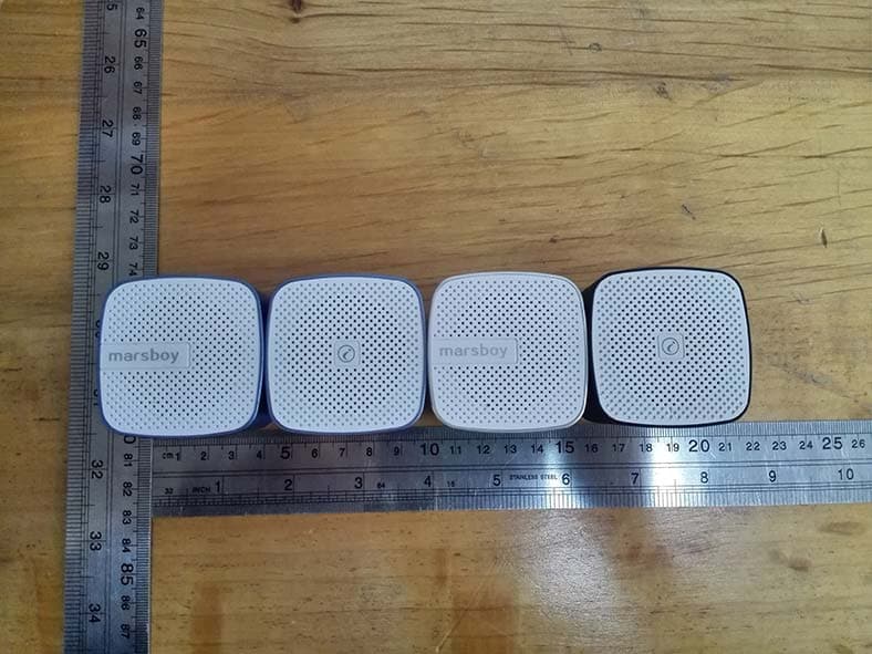
2AA4V0003
Nov 30, 2015Bluetooth Speaker
Equipment Class
DSS - Part 15 Spread Spectrum Transmitter
2AA4V0001
Oct 23, 2013Bluetooth Speaker
Equipment Class
DSS - Part 15 Spread Spectrum Transmitter