2AA5BGLCSB00Smart Band
GOYOURLIFE INC.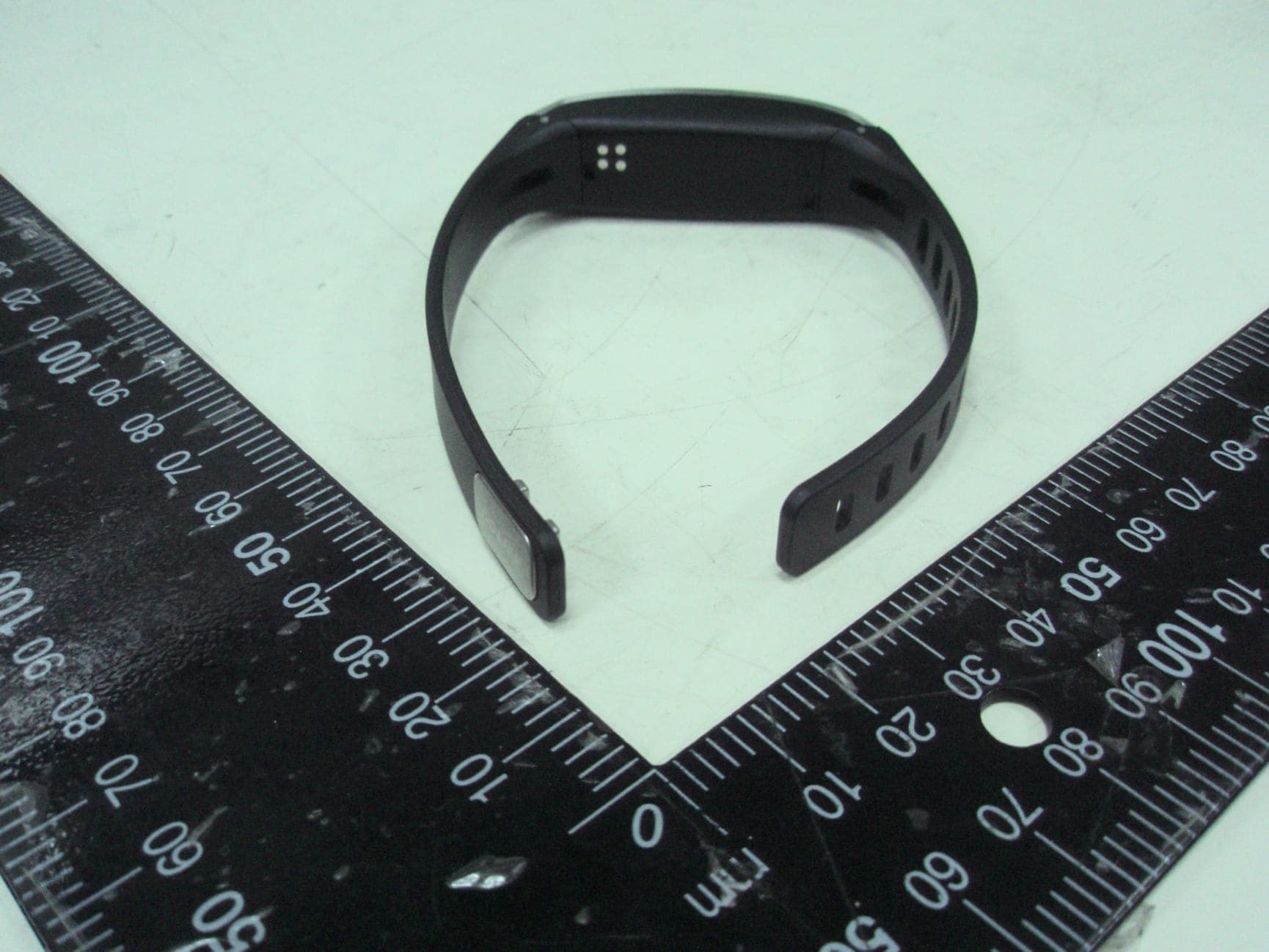
Click to zoom
Application Details
- Equipment Class
- DTS - Digital Transmission System
- Date of Grant
- Aug 26, 2014
- Application Purpose
- Original Equipment
- Date of Application
- Aug 26, 2014
- Equipment Note
- Smart Band
- Frequency Range
- 2402.00000000 - 2480.00000000
- Company
- GOYOURLIFE INC.
- Country
- Taiwan
Documents & Files
Document Text
Text extracted from the exhibit documents filed with the FCC. Open a document above to read the original.
Users Manual
The Federal Communication Commission Statement This equipment has been tested and found to comply with the limits for a Class B Digital Device, pursuant to Part 15 of the FCC rules. These limits are designed to provide reasonable protection against harmful interference in a residential installation. This equipment generates, uses and can radiate radio frequency energy and, if not installed and used in accordance with the instruction, may cause harmful interference to radio communication. However, there is no guarantee that interference will not occur in a particular installation. If this equipment does cause harmful interference to radio or television reception, which can be determined by turning the equipment off and on, the user is encouraged to try to correct the interference by one of more of the following measures: - - Reorient or relocate the receiving antenna. - Increase the separation between the equipment and receiver. - Connect the equipment into an outlet on a circuit different from that to which the receiver is connected. - Consult the dealer or an experienced Radio/TV technician for help. Use only shielded cables to connect I/O devices to this equipment. You are cautioned that change or modifications not expressly approved by the party responsible for compliance could void your authority to operate the equipment. THIS DEVICE COMPLIES WITH PART 15 OF FCC RULES. OPERATION IS SUBJECT TO THE FOLLOWING TWO CONDITIONS: 1 This device may not cause harmful interference and 2 This device must accept any interference received, including interference that may cause undesired operation. The antenna used for this transmitter must not be collocated or operation in conjunction with any other antenna or transmitter. Notice : The changes or modifications not expressly approved by the party responsible for compliance could void the user’s authority to operate the equipment. IMPORTANT NOTE: To comply with the FCC RF exposure compliance requirements, no change to the antenna or the device is permitted. Any change to the antenna or the device could result in the device exceeding the RF exposure requirements and void user’s authority to operate the device. GOLiFE Care Smart Band Press the Smart Band button to start use. appuyez sur la touche Band intelligent de commencer à utiliser. 5 Bande à puce GOLiFE Care Attention when first time use Please connect the USB cable to charge, and press the Smart Band button to start use. Attention lors de la première utilisation du temps S’il vous plaît connecter le câble USB pour recharger, et appuyez sur la touche Band intelligent de commencer à utiliser. Correctly line up the band with the charger contact, And close the lid to begin charging. GOLiFE Care Smart Band Display screen Button ClaspGOLiFE Care Smart BandUSB Cord 7 GOLiFE Care Wearing and charging Charging Method Correctly line up the band with the charger contact, And close the lid to begin charging. How to Wear Upon wearing, check the direction displayed by the band screen, U-shape display screen facing up. U-shape display screen facing up GOLiFE Care Smart Band adjustable detent pin Inbox contain: M/L wristband, adjustable detent pin and detent pin. ML detent pin Adjust wristband and accordance with the comfortable of wearing to replace the wristband. 9 GOLiFE Care Wearing and charging 1 2 4 3 Replace the strap When replacing, please pull out the adjustable detent pin. Removing the strap. 1 2 4 3 Placing the other strap to a fixed position. After inserting the detent pin and complete the replacement. GOLiFE Care Smart Band Setting up GOLiFE Care smart band Launch the APP and register a GOLiFE account (account users can log in directly). Launch the APP and select “My Device”. Follow the steps as instructed to connect with GOLiFE Care. Before pairing via Bluetooth, make sure Bluetooth connection on the mobile device is turned on. (Go to “Settings” → “Bluetooth” → “Open” on the mobile device.) Downloading and installing GOLiFE Fit APP: Download and install the APP using the two methods below Scan the QR code or search for in or App StoreGoogle playGOLiFE Fit 11 Install and setup the GOLiFE Fit APP Place the band near the mobile device, and select “Connect to GOLiFE Care”. Wait for a pairing code to be generated. Enter the pairing code to the APP to complete the pairing. Connect to GOLiFE Care Launch the APP and register a GOLiFE account (account users can log in directly). Launch the APP and select “My Device”. Follow the steps as instructed to connect with GOLiFE Care. Before pairing via Bluetooth, make sure Bluetooth connection on the mobile device is turned on. (Go to “Settings” → “Bluetooth” → “Open” on the mobile device.) Downloading and installing GOLiFE Fit APP: Download and install the APP using the two methods below Scan the QR code or search for in or GOLiFE Care Smart Band Activity Mode Time/Date Short press to switch to a different data display. Long press to switch to the “Activity/Sleep” mode. (To correctly record data, switch to the corresponding mode on the band before sleeping or after waking up) Number of stepsDistanceCaloriesAmount of electricity 13 Use GOLiFE Care Sleep Mode Sleep Set up an alarm and incoming call through the APP. Launch the APP regularly to sync data to the cellphone. Time/DateAmount of electricityAlarm clock Incoming call Daily Life Connect/ Disconnect the device Short press to switch to a different data display. Long press to switch to the “Activity/Sleep” mode. (To correctly record data, switch to the corresponding mode on the band before sleeping or after waking up) Bande à puce GOLiFE Care L’écran Les boutons Le fermoirBande à puce GOLiFE CareLe câble USB 15 Le port et la charge GOLiFE Care Le procédé de charge Aligner correctement la bande avec l’endroit où le chargeur pourra la détecter et fermer le couvercle pour commencer la charge Comment porter la bande Lors de la mise en place, vérifier la direction affichée à l’écran de la bande La forme en U devrai…
Text truncated - open the document above for the full version.
Cover Letter(s)
GOYOURLIFE INC. 6F., No. 189, Xinhu 3rd Rd., Neihu Dist., Taipei City 114, Taiwan (R.O.C.) Tel: +886-2-87921567 FAX: +886-2-87921167 Date: AUG. 11, 2014 Equipment Autorisation Division Federal Communications Commission 7435 Oakland Mills Road Columbia, MD 21046 FCC ID: 2AA5BGLCSB00 Product Name: Smart Band Request for Short-Term Confidentiality Pursuant to Sections 0.457 and 0.459 of the commission rules, and in accordance with the FCC Public notice dated June 15, 2004 (DA 04-1705), we hereby request short-term confidentiality for the following items prior to marketing the device.: Test Setup Photos External Photos Internal Photos User Manual These documents contain detailed system and equipment description and related information about the product which GOYOURLIFE INC. considers to be proprietary, confidential, and a custom design and, otherwise would not release to the general public. Since this design is a basis from which future technological products will evolve, GOYOURLIFE INC. considers this information to be of benefit to its competitors, and that the disclosure of information in these documents would give competitors an unfair advantage in the market. This request is being made retroactively due to an over site on our part. We understand that the information has been publicly available 180 days after date of grant. Dated this 08/11/2014 By: Signature Printed Title: Director On behalf of : GOYOURLIFE INC. Telephone: +886-2-87921567
Cover Letter(s)
GOYOURLIFE INC. 6F., No. 189, Xinhu 3rd Rd., Neihu Dist., Taipei City 114, Taiwan (R.O.C.) Tel: +886-2-87921567 FAX: +886-2-87921167 Date: AUG. 11, 2014 Equipment Autorisation Division Federal Communications Commission 7435 Oakland Mills Road Columbia, MD 21046 FCC ID: 2AA5BGLCSB00 Product Name: Smart Band Request for Confidentiality Pursuant to Sections 0.457 and 0.459 of the commissions rules, we hereby request that the following documents be held confidential: (List here the documents for which you are seeking confidentiality – for example ...) Schematics Block diagram Operation description These materials contain trade secrets and proprietary information and are not customarily released to the public. The public disclosure of this information might be harmful to the company and provide unjustified benefits to our competitors. Dated this 08/11/2014 By: Signature Printed Title: Director On behalf of : GOYOURLIFE INC. Telephone: +886-2-87921567
External Photos
Report No. : 14062703 01 Front view of EUT 02 Rear view of EUT Report No. : 14062703 03 Front view of Series 04 Rear view of Series
ID Label/Location Info
Label location
Internal Photos
Report No. : 14062703 05 Inside view of EUT 06 Inside view of EUT Report No. : 14062703 07 Inside view of EUT 08 PCB-F Report No. : 14062703 09 PCB-R 10 Cable
RF Exposure Info
PEP Certification Corp. Date of Issue: Aug 19, 2014 Report No. : F14062703 Page No. : 1 of 1 Radio Frequency Exposure EUT INFORMATION EUT Smart Band Frequency band (Operating) Bluetooth: 2.402 GHz ~ 2.480 GHz Antenna diversity Single antenna Multiple antennas Tx diversity Rx diversity Tx/Rx diversity Max. output power GFSK: 1.83 dBm (1.524 mW) Antenna gain (Max) 0 dBi TEST RESULT According to KDB 447498 section 4.3.1, the 1-g SAR test exclusion thresholds at test separation distance ≤ 50 mm are determined by: [(max. power of channel, including tune-up tolerance, mW) / (min. test separation distance,mm)] *[√ f(GHz)] ≤ 3.0 The max. average power of channel, including tune-up tolerance(mW) is 1.524 mW @ 2480 MHz (With Tune-up tolerance), The min. test separation distance (mm) is 5 mm, So, [(max. power of channel, including tune-up tolerance, mW) / (min. test separation distance, mm)] *[√ f(GHz)] = 0.480 < 3.0 (With Tune-up tolerance). Therefore, standalone SAR measurements are not required for both head and body.
Test Report
PEP Certification Corp. Date of Issue: AUG. 05, 2014 Report No. : F14062703 Page No. : 1 of 43 FCC 47 CFR PART 15 SUBPART C 15.247 TEST REPORT FOR Smart Band Model : GOLiFE Care Trade Name: GOLiFE Issued to GOYOURLIFE INC. 6F., No. 189, Xinhu 3rd Rd., Neihu Dist., Taipei City 114, Taiwan (R.O.C.) Issued by PEP Certification Corp. Open Site No. 120, Ln. 5, Hudong St., Xizhi Dist., New Taipei City 221, Taiwan (R.O.C.) EMC Test Site Xizhi Office and Lab 12F.-3, No.27-1, Ln. 169, Kangning St., Xizhi Dist., New Taipei City 221, Taiwan (R.O.C.) Note: This test refers exclusively to the test presented test model and sample. This report shall not be reproduced except in full, without the written approval of PEP Certification Corp. This document may be altered or revised by PEP Certification Corp. Personnel only, and shall be noted in the revision section of the document. PEP Certification Corp. Date of Issue: AUG. 05, 2014 Report No. : F14062703 Page No. : 2 of 43 Contents Appendix A. 1. General Information ................................................................................................... 3 2. Report of Measurements and Examinations ................................................................................ 5 2.1 List of Measurements and Examinations ............................................................................... 5 3. Test Configuration of Equipment under Test ............................................................................... 6 3.1 Description of the tested samples .......................................................................................... 6 3.2 Carrier Frequency of Channels .............................................................................................. 7 3.3 Test Mode and Test Software ................................................................................................ 8 3.4 TEST Methodology & General Test Procedures ..................................................................... 9 3.5 Measurement Uncertainty ................................................................................................... 10 3.6 Description of the Support Equipments ................................................................................ 10 4. Test and measurement equipment ............................................................................................. 11 4.1 calibration ........................................................................................................................... 11 4.2 equipment ........................................................................................................................... 11 5. Antenna Requirements ................................................................................................................ 13 5.1 Standard Applicable ............................................................................................................ 13 5.2 Antenna Construction and Directional Gain ......................................................................... 13 6. Test of Conducted Emission ....................................................................................................... 14 6.1 Test Limit ............................................................................................................................ 14 6.2 Test Procedures .................................................................................................................. 14 6.3 Typical Test Setup ............................................................................................................... 15 6.4 Test Result and Data ........................................................................................................... 16 7. Test of Radiated Emission .......................................................................................................... 18 7.1 Test Limit ............................................................................................................................ 18 7.2 Test Procedures .................................................................................................................. 18 7.3 Typical Test Setup ............................................................................................................... 19 7.4 Test Result and Data (9kHz ~ 30MHz) ................................................................................. 20 7.5 Test Result and Data (30MHz ~ 1GHz, worst emissions found)............................................ 20 7.6 Test Result and Data (Above 1GHz) .................................................................................... 22 8. 6dB Bandwidth Measurement Data ............................................................................................. 28 8.1 Test Limit ............................................................................................................................ 28 8.2 Test Procedures .................................................................................................................. 28 8.3 Test Setup Layout ............................................................................................................... 28 8.4 Test Result and Data ........................................................................................................... 29 9. Maximum Peak and Average Output Power ............................................................................... 32 9.1 Test Limit ............................................................................................................................ 32 9.2 Test Procedures .................................................................................................................. 32 9.3 Test Setup Layout ............................................................................................................... 32 9.4 Test Result and Data ...........................................................…
Text truncated - open the document above for the full version.
Test Setup Photos
Global Certification Corp. Appendix 1 PHOTOS OF TEST CONFIGURATION Report No. : F14062703 01 RF-CE Front View 02 RF-CE Rear View Report No. : F14062703 03 RF-RE Front View 04 RF-RE Rear View Report No. : F14062703 05 RF-RE Front View(1-25G) 06 RF-RE Rear View(1-25G)
Contact Information
Applicant
CHE YU LIU
Test Firm
PEP Certification Corp.Alex Chou
Technical Specifications
| # | Rule Parts | Frequency Range | Power Output |
|---|---|---|---|
| 1 | 15C | 2.40 GHz - 2.48 GHz | 1.52 mW |
Other Applications from GOYOURLIFE INC.
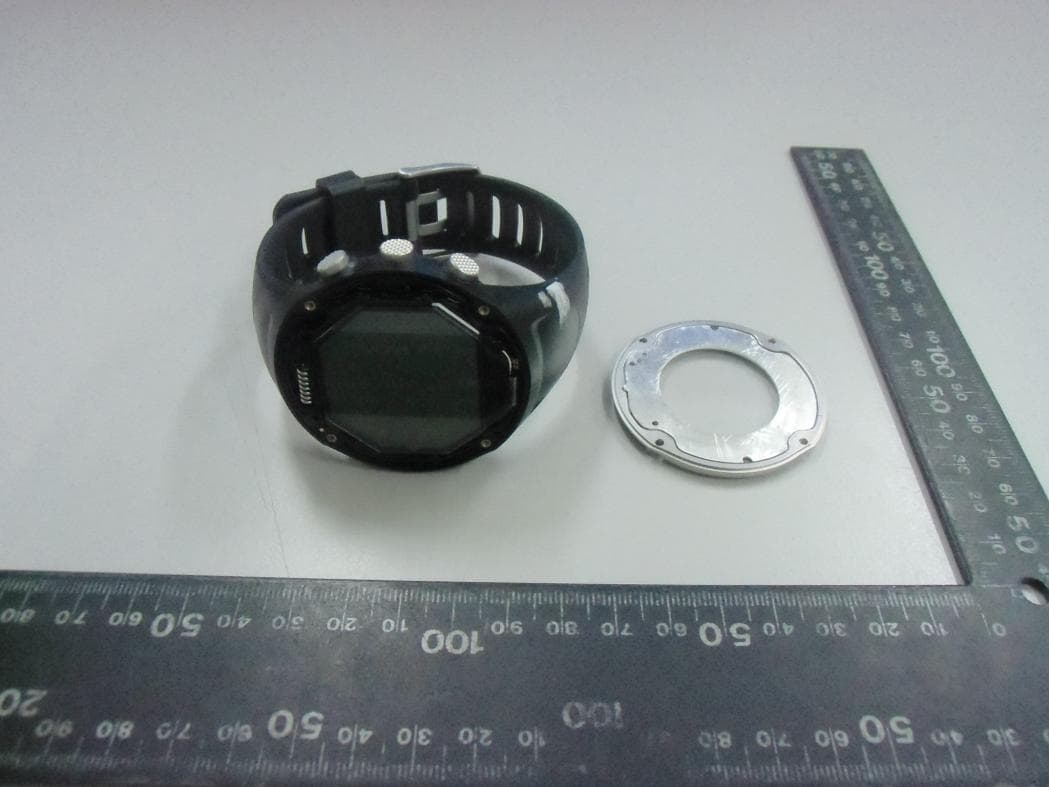
2AA5BGLGWPRO
Jul 06, 2015GPS Sport Watch
Equipment Class
DTS - Digital Transmission System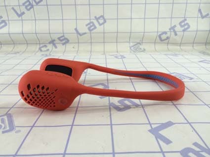
2AA5BGLWAVE0
Mar 16, 2015GOLiFE WAVE Bluetooth Speaker
Equipment Class
DXX - Part 15 Low Power Communication Device Transmitter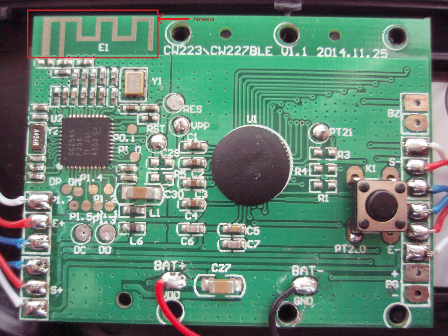
2AA5BGLFPBK1
Jan 26, 2015Bluetooth Smart Scale
Equipment Class
DTS - Digital Transmission System
2AA5BGLGW820
Jan 14, 2015GPS Sport Watch
Equipment Class
DTS - Digital Transmission System