2AA64CB900GSM Module
Shenzhen Coban Electronics Co., Ltd.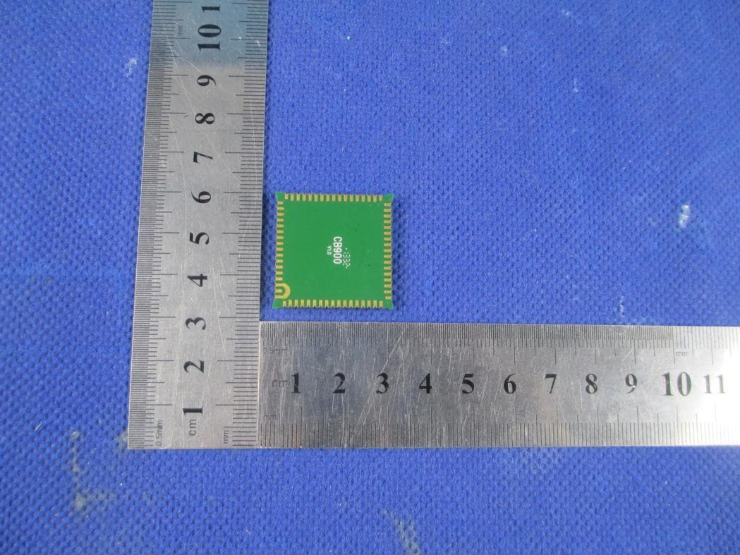
Click to zoom
Application Details
- Equipment Class
- PCB - PCS Licensed Transmitter
- Date of Grant
- Nov 16, 2013
- Application Purpose
- Original Equipment
- Date of Application
- Nov 16, 2013
- Equipment Note
- GSM Module
- Frequency Range
- 1850.20000000 - 1909.80000000
- Country
- China
Documents & Files
Document Text
Text extracted from the exhibit documents filed with the FCC. Open a document above to read the original.
Users Manual
CB900 GSM/GPRS Module Product Technical Specifications Date : 2013-9-11 Document Version : 1.1 Our Reference : 02000B33 CONTENTS 1. Introduction ....................................................................................................................... 3 1.1. Abbreviations ......................................................................................................... 3 1.2. Safety Precautions ................................................................................................... 4 2. Technical Specifications ..................................................................................................... 5 2.1. General Specifications ............................................................................................. 5 2.2. GSM/ GPRS Specifications ..................................................................................... 5 2.3. RF Frequencies ....................................................................................................... 6 2.4. Baseband Functionalities ......................................................................................... 6 2.5. Interface Specifications ........................................................................................... 6 3. Functional Architecture ...................................................................................................... 7 4. INTERFACES ................................................................................................................... 8 4.1. Pin Assignments...................................................................................................... 8 4.2. Pin description ........................................................................................................ 9 4.3. Power Supply and Ground ..................................................................................... 11 4.4. Operating Modes................................................................................................... 12 4.5. Analog to Digital Converter (ADC) ....................................................................... 13 4.6. Power ON Control ................................................................................................ 13 4.7. Subscriber Identity Module (SIM) Interface ........................................................... 14 4.8. Serial Link (UART) Interfaces ............................................................................... 15 4.9. USB Interface ....................................................................................................... 17 4.10. Analog Audio Interfaces .................................................................................... 18 4.10.1. Microphone input ...................................................................................... 18 4.10.2. Speaker ..................................................................................................... 19 4.10.3. Earphone ................................................................................................... 20 4.11. General Purposes Input / Output ports .................................................................... 21 4.12. Keyboard Interface ............................................................................................ 21 4.13. 2-Wire Serial Interface ...................................................................................... 22 4.14. RF interface ...................................................................................................... 22 4.14.1. RF Performance ......................................................................................... 22 4.14.2. Recommendations...................................................................................... 22 1. Introduction This document describes the hardware interface, including interface specifications, electrical and mechanical details, of the CB900 module that connects to the cellular device application. 1.1. Abbreviations The following abbreviations are used in this document: Abbreviation Description ACM Accumulated Call Meter ADC Analog Digital Convertor AMR Adaptive Multi-rate AMR- FR AMR Full-rate ADN Abbreviated Dialing Number APN Access Point Name CLIP Calling Line Identity Presentation CSD Circuit Switched Data DCD Data Carrier Detect DCE Data Communication Equipment DCS Data Coding Scheme DTE Data Terminal Equipment DTMF Dual Tone Multi Frequency DTR Data Terminal Ready EFR Enhanced Full-rate FR Full-rate GPIO General Purpose Input Output GPRS General Packet Radio Service GSM Global Standard for Mobile Communications IP Internet Protocol PDP Packet Data Protocol PDU Packet Data Unit PPP Point-to-Point Protocol RF Radio Frequency RTS Ready To Send SIM Subscriber Identification Number SMS Short Messages Service TCP Transmission Control Protocol UART Universal Asynchronous Receiver Transmitter UDP User Data Protocol USSD Unstructured Supplementary Service Data 1.2. Safety Precautions For your own safety, please follow the safety precautions listed below during all phases of the operation, usage, service or repair of any cellular terminal or mobile incorporating the CB900 Module. All manufacturers of these cellular terminals or mobile devices are advised to include the following safety precautions into all manuals provided with their terminal or mobile device, and pass this information to device users and operating personnel. Failure to comply may be dangerous or illegal. Road safety Do not use a mobile device while driving. Park the vehicle first or use a hand free earphone. It is illegal in some countries to use a mobile device while driving. Switch off in aircraft Cellular terminal or mobile devices can cause interference to aircraft electronics. Using them on aircraft is both illegal and dangerous. Switch off when refueling vehicle Do not use the cellular terminal or mobile device at a refueling station or near fuels or chemicals. Forbidden Usage Always…
Text truncated - open the document above for the full version.
Cover Letter(s)
Shenzhen Coban Electronics Co., Ltd. SCS-F18: Project and Product Certification Representative Authorization Letter Page 1 of 2 Rev 3.0 775 Montague Expressway Milpitas, CA 95035 Tel: 408-526-1188 Fax: 408-526-1088 Email: [email protected] Project and Product Certification Representative Authorization Letter Reason for Amendment (current / obsolete) Revision History Approved Date From To Initial Release (obsolete) 1.0 1.0 Nov-14-2006 Revised wording (obsolete) 1.0 2.0 Sept–25-2007 Updated company template (current) 2.0 3.0 Jan-31-2012 Shenzhen Coban Electronics Co., Ltd. SCS-F18: Project and Product Certification Representative Authorization Letter Page 2 of 2 Rev 3.0 2013/10/22 To: SIEMIC, INC. 775 Montague Expressway, Milpitas, CA 95035 USA Dear Sir/Madam, Re: Project and Product Certification Representative Authorization Letter We, _____ Shenzhen Coban Electronics Co., Ltd. _____hereby authorize SIEMIC, INC. to act as a Certification Body for certifying for the following project(s): Product: GSM Module Trade Name: Coban Model Name: CB900 Serial Model: N/A FCC ID 2AA64CB900 We affirm that between SIEMIC and ___ Shenzhen Coban Electronics Co., Ltd. ___, any difference in understanding, including test plan, measurement methods, applicable standards and relevant procedures and processes have been resolved prior to commencement of testing activities. Sincerely, ----------------------------- Client’s signature Client’s name / title : Nianyong Wei/ Manger Contact information / address : No.601, 6/F, Bldg. 8, Zhiheng Industries Park, Guankou 2nd Road, Nantou, Nanshan District, Shenzhen, Guangdong,China
Cover Letter(s)
Shenzhen Coban Electronics Co., Ltd. SCS-F19: Confidentiality Request Letter Page 1 of 2 Rev 3.0 775 Montague Expressway Milpitas, CA 95035 Tel: 408-526-1188 Fax: 408-526-1088 Email: [email protected] Confidentiality Request Letter Reason for Amendment (current / obsolete) Revision History Approved Date From To Initial Release (obsolete) 1.0 1.0 Nov-14-2006 Adding CFR 2.459 (obsolete) 1.0 2.0 August – 11 - 2008 Updated company template & Added text box (current) 2.0 3.0 Jan-31-2012 Shenzhen Coban Electronics Co., Ltd. SCS-F19: Confidentiality Request Letter Page 2 of 2 Rev 3.0 2013/10/22 To: Federal Communications Commission Authorization and Evaluation Division 7435 Oakland Mills Road Columbia, MD Subject: Permanent Confidentiality Request for FCC ID: 2AA64CB900 We hereby request confidential treatment of information accompanying this application as outlined below: - Block Diagram - Schematics - Operational Description - Bom and tune up The above materials contain trade secrets and proprietary information not customarily released to the public. The public disclosure of these materials may be harmful to the applicant and provide unjustified benefits to its competitors. The applicant understands that pursuant to Section 0.457 & 0.459 of the Rules, disclosure of this application and all accompanying documentation will not be made before the date of the Grant for this application. Sincerely, ----------------------------- Client’s signature Client’s name / title : Nianyong Wei/ Manger Contact information / address : No.601, 6/F, Bldg. 8, Zhiheng Industries Park, Guankou 2nd Road, Nantou, Nanshan District, Shenzhen, Guangdong,China
Cover Letter(s)
SCS-F26 Modular Approval Letter Page 1 of 2 Rev 7.0 775 Montague Expressway Milpitas, CA 95035 Tel: 408-526-1188 Fax: 408-526-1088 Email: [email protected] Modular Approval Declaration Letter Reason for Amendment (current / obsolete) Revision History Approved Date From To Initial Release (Obsolete) 1.0 1.0 Dec-04-2006 Added IC Modular Letter (Obsolete) 1.0 2.0 Feb 16 2009 Add LMA and MA option (Obsolete) 2.0 3.0 April 14 2010 Revised per RSS Gen issue 3.0 (Obsolete) 3.0 4.0 Jan 12 2011 Removed Foot(2) (obsolete) 4.0 5.0 July 19 2011 Adding New note per KDB996369 D01 V01R03 (obsolete) 5.0 6.0 August 29 2011 Updated company template & Added text box (current) 6.0 7.0 Jan-31-2012 SCS-F26 Modular Approval Letter Page 2 of 2 Rev 7.0 Shenzhen Coban Electronics Co., Ltd. (Date) 11/08/2013 (Product name) FCC ID : 2AA64CB900 , is seeking FCC Authorization as a Single Modular transmitter / Single Limited Modular Approval (Please check one). The EUT meets the requirements for Single Modular approval / Single Limited Modular Approval (please check one) as detailed in FCC public Notice DA00-1407. Compliance to each of the requirements is described below: Questions are: * Please provide a detailed explanation if the answer is “No.” 1. “The modular transmitter must have its own RF shielding.” Yes / No 2. “The modular transmitter must have buffered modulation/data inputs.” Yes / No 3. “The modular transmitter must have its own power supply regulation.” Yes / No 4. “The modular transmitter must comply with the antenna requirements of section 15.203 and 15.204(c).” Yes / No 5. “The modular transmitter must be tested in a stand-alone configuration.” Yes / No 6. “The modular transmitter must be labeled with its own FCC ID number.” Yes / No 7. “The modular transmitter must comply with any specific rule or operating requirements applicable to the transmitter and the manufacture must provide adequate instruction along with the module to explain any such requirements.” Yes / No 8. “The modular transmitter must comply with any applicable RF exposure requirements.” Yes / No Note: (1) LMA may be granted when one or more of the requirements in the table above cannot be demonstrated. LMA will also be issued in those instances where applicants can demonstrate that they will retain control over the final installation of the device, such that compliance of the end product is assured. In such cases, an operating condition on the LMA for the module must state that the module is only approved for use when installed in devices produced by a specific manufacturer. When LMA is sought, the application for equipment certification must specifically state how control of the end product into which the module will be installed, and will be maintained, such that full compliance of the end product is always ensured. (2) Please provide Clear and specific instructions describing the conditions, limitations and procedures for third-parties to use and/or integrate the module into a host device. (3) For non-Software Defined Radio transmitter modules where software is used to ensure compliance of the device, technical description of how such control is implemented to ensure prevention of third party modification must be provided (see KDB 594280). Note 1: Compliance of a module in its final configuration is the responsibility of the applicant. A host device will not be considered certified if the instructions regarding antenna configuration provided in the original description, of one or more separately certified modules it contains, were not followed. Example: A separately certified low-power transceiver module using Bluetooth technology which is housed in a desktop computer, laptop or peripheral does not require the overall system to be recertified, if the desktop computer, laptop or peripheral, as a stand-alone unit, complies with all applicable technical standards. ----------------------------- Client’s signature Client’s name / title : Nianyong Wei/ Manger Contact information / address : No.601, 6/F, Bldg. 8, Zhiheng Industries Park, Guankou 2nd Road, Nantou, Nanshan District, Shenzhen, Guangdong,China
External Photos
APPENDIX-PHOTOGRAPHS OF EUT CONSTRUCTIONAL DETAILS Photo 1 Photo 2 Photo 3 Photo 4
ID Label/Location Info
GSM Module Model: CB900 FCC ID: 2AA64CB900 Shenzhen Coban Electronics Co., Ltd. Made in China Label
Internal Photos
APPENDIX-PHOTOGRAPHS OF EUT CONSTRUCTIONAL DETAILS Photo 1 Photo 2 Photo 3 Photo 4
RF Exposure Info
FCC ID: 2AA64CB900 RF EXPOSURE TEST Applied procedures / limit These devices are not exempted from compliance does not exceed the Commission’s RF exposure guidelines.Unless a device operates at substantially low power levels,with a low gain antenna(s),supporting information is generally needed to establish the various potential operating configurations and exposure conditions of a transmitter and its antenna(s) in order to determine compliance with the RF exposure guidelines. In order to demonstrate compliance with MPE requirement(see Section 2.1091),the following information is typically needed: Calculation that estimates the minimum separation distance(20 cm or more)between an antenna and persons required to satisfy power density limits defined for free space. Antenna installation and device operating instructions for installers(professional/unskilled users),and the parties responsible for ensuring compliance with the RF exposure requirement Any caution statements and/or warming labels that are necessary in order to comply with the exposure limits Any other RF exposure related issues that may affect MPE compliance. FCC 1.1310: The criteria listed in the following table shall be used to evaluate the environmental impact of human exposure to radio-frequency(RF) radiation as specified in 1.1307(b). (A) Limits for Occupational / Controlled Exposure Frequency Range (MHz) Electric Field Strength (E) (V/m) Magnetic Field Strength (H) (A/m) Power Density (S) (mW/ cm 2 ) Averaging Time |E| 2 ,|H| 2 or S (minutes) 0.3-3.0 614 1.63 (100)* 6 3.0-30 1842 / f 4.89 / f (900 / f)* 6 30-300 61.4 0.163 1.0 6 300-1500 F/300 6 1500-100,000 5 6 (B) Limits for General Population / Uncontrolled Exposure Frequency Range (MHz) Electric Field Strength (E) (V/m) Magnetic Field Strength (H) (A/m) Power Density (S) (mW/ cm 2 ) Averaging Time |E| 2 ,|H| 2 or S (minutes) 0.3-1.34 614 1.63 (100)* 30 1.34-30 824/f 2.19/f (180/f)* 30 30-300 27.5 0.073 0.2 30 300-1500 F/1500 30 1500-100,000 1.0 30 Note: f = frequency in MHz ; *Plane-wave equivalent power density FCC ID: 2AA64CB900 MPE CALCULATION METHOD Calculation Method of RF Safety Distance: P :power input to the antenna in Mw EIRP :Equivalent(effective) isotropic radiated power. S :power density mW/ cm 2 G ;numeric gain of antenna relative to isotropic radiator R :distance to centre of radiation in cm FCC radio frequency exposure limits may be exceeded at distances closer than r cm from the antenna of this device EIRP=10 ( Antenna Gain+Peak Output Power/10) Note: 1. s=1.0 mW /cm 2 for limits for General Population/Uncontrolled Exposures. 2. The time averaged power over 30 minutes will be equaled Output Power. 3. The Power Density at a distance of 20cm calculated from the formula is far below the limit of 1MW/ cm 2 FCC ID: 2AA64CB900 TEST RESULTS Mode Max Tune up power, dBm Max time average power, dBm GSM 850 (1 up) 33 24 GPRS850 Class 8 , GMSK (1up) 33 24 GPRS850 Class 10 , GMSK (2up) 31 25 GPRS850 Class 12 , GMSK (4up) 27 24 GSM 1900 (1 up) 31 22 GPRS1900 Class 8 , GMSK (1up) 31 22 GPRS1900 Class 10 , GMSK (2up) 29 23 GPRS1900 Class 12 , GMSK (4up) 25 22 Based on above table , GPRS 850 Class 10 and GPRS 1900 Class 10 has highest time average power output power (MAX) (dBm) Output power to antenna (mW) Antenna Gain (numeric) Power Density (S) (mW/ cm 2 ) Limit of Power Density (S) (mW/ cm 2 ) Result 25 (GSM 850) 316.23 1.58(2dbi) 0.0995 0.549 Pass 23 (PCS 1900) 199.53 1.58(2dbi) 0.0628 1 Pass
Test Report
RADIO TEST REPORT FCC ID: 2AA64CB900 Product: GSM Module Trade Name: N/A Model Name: CB900 Serial Model: N/A Report No.: BZT131022057 Prepared for Shenzhen Coban Electronics Co., Ltd. No.601, 6/F, Bldg. 8, Zhiheng Industries Park, Guankou 2nd Road, Nantou, Nanshan District, Shenzhen, Guangdong,China Prepared by BZT Testing Technology Co., Ltd Add. : 1/F, Building E, Fenda Science Park, Sanwei Community, Xixiang Street, Bao’an District, Shenzhen P.R. China. Page 2 of 53 Report No.: BZT131022057 ` TEST RESULT CERTIFICATION Applicant’s name ................. : Shenzhen Coban Electronics Co., Ltd. Address ................................. : No.601, 6/F, Bldg. 8, Zhiheng Industries Park, Guankou 2nd Road, Nantou, Nanshan District, Shenzhen, Guangdong,China Manufacture's Name ............ : Shenzhen Coban Electronics Co., Ltd. Address ................................. : No.601, 6/F, Bldg. 8, Zhiheng Industries Park, Guankou 2nd Road, Nantou, Nanshan District, Shenzhen, Guangdong,China Product description Product name............................ : GSM Module Model and/or type reference : CB900 Serial Model .............................. : N/A Standards ............................. : FCC Part 22H and 24E Test procedure ............................... : ANSI C63.4-2003, RSS-Gen Issue 3 This device described above has been tested by BZT, and the test results show that the equipment under test (EUT) is in compliance with the FCC requirements. And it is applicable only to the tested sample identified in the report. This report shall not be reproduced except in full, without the written approval of BZT, this document may be altered or revised by BZT, personal only, and shall be noted in the revision of the document. Date of Test ........................................... : Date (s) of performance of tests ............. : 10 Oct 2013 ~19 Oct 2013 Date of Issue .......................................... : 20 Oct 2013 Test Result.............................................. : Pass Page 3 of 53 Report No.: BZT131022057 ` Table of Contents Page 1 . SUMMARY OF TEST RESULTS 5 1.1 TEST FACILITY 6 1.2 MEASUREMENT UNCERTAINTY 6 2 . GENERAL INFORMATION 7 2.1 GENERAL DESCRIPTION OF EUT 7 2.2 DESCRIPTION OF TEST MODES 8 2.3 BLOCK DIGRAM SHOWING THE CONFIGURATION OF SYSTEM TESTED 9 2.4 DESCRIPTION OF SUPPORT UNITS(CONDUCTED MODE) 10 2.5 EQUIPMENTS LIST FOR ALL TEST ITEMS 11 3 . TEST RESULT 12 3.1 ANTENNA REQUIREMENT 12 3.1.1 STANDARD REQUIREMENT 12 3.1.2 EUT ANTENNA 12 3.2 OUTPUT POWER 13 3.2.1 CONDUCTED OUTPUT POWER 13 3.2.2 RADIATED OUTPUT POWER 14 3.3 SPURIOUS EMISSION 17 3.3.1 CONDUCTED SPURIOUS EMISSION 17 3.3.2 RADIATED SPURIOUS EMISSION 19 3.4 FREQUENCY STABILITY 23 3.4.1 MEASUREMENT METHOD 23 3.4.2 PROVISIONS APPLICABLE 23 3.5 OCCUPIED BANDWIDTH 26 3.5.1 MEASUREMENT METHOD 26 3.5.2 PROVISIONS APPLICABLE 26 3.5.3 MEASUREMENT RESULT 26 3.6 EMISSION BANDWIDTH 27 3.6.1 MEASUREMENT METHOD 27 3.6.2 PROVISIONS APPLICABLE 27 3.6.3 MEASUREMENT RESULT 27 3.7 BAND EDGE 28 3.7.1 MEASUREMENT METHOD 28 3.7.2 PROVISIONS APPLICABLE 28 3.7.3 MEASUREMENT RESULT 28 APPENDIX I 29 APPENDIX II 41 APPENDIX III 47 Page 4 of 53 Report No.: BZT131022057 ` Table of Contents Page APPENDIX IV 51 4 . EUT TEST PHOTO 53 APPENDIX-PHOTOGRAPHS OF EUT CONSTRUCTIONAL DETAILS Page 5 of 53 Report No.: BZT131022057 ` 1. SUMMARY OF TEST RESULTS Test procedures according to the technical standards: Item Number Item Description Rules Result 1 Output Power Conducted Output Power 22.913(a) / 24.232 (b) RSS-132(5.4) SRSP-503(5.1.3) Pass Radiated Output Power 2 Spurious Emission Conducted Spurious Emission 2.1051 / 22.917 / 24.238 RSS-132(5.5) RSS-133 (6.5) Pass Radiated Spurious Emission 3 Frequency Stability 2.1055 /24.235 RSS-132(5.3) RSS-133(6.3) Pass 4 Occupied Bandwidth 2.1049 (h)(i) Pass 5 Emission Bandwidth 22.917(b) / 24.238 (b) RSS-132(5.5.1) RSS-133(6.5.1) Pass 6 Band Edge 22.917(b) / 24.238 (b) RSS-132(5.5.1) RSS-133(6.5.1) Pass Page 6 of 53 Report No.: BZT131022057 ` 1.1 TEST FACILITY BZT Testing Technology Co., Ltd Add. : 1/F, Building E, Fenda Science Park, Sanwei Community, Xixiang Street, Bao’an District, Shenzhen P.R. China. FCC Registration No.: 701733 1.2 MEASUREMENT UNCERTAINTY The reported uncertainty of measurement y ± U,where expended uncertainty U is based on a standard uncertainty multiplied by a coverage factor of k=2,providing a level of confidence of approximately 95 %。 No. Item Uncertainty 1 Conducted Emission Test ±1.38dB 2 Radiated Emission Test ±3.17dB 3 RF power,conducted ±0.16dB 4 Spurious emissions,conducted ±0.21dB 5 All emissions,radiated(<1G) ±4.68dB 6 All emissions,radiated(>1G) ±4.89dB Page 7 of 53 Report No.: BZT131022057 ` 2. GENERAL INFORMATION 2.1 GENERAL DESCRIPTION OF EUT Equipment GSM Module Trade Name N/A Model Name CB900 OEM Brand/Model Name N/A Model Difference N/A Frequency: GSM 850 MHz;:824.2-848.4MHz PCS 1900 MHz: 1850.2-1909.8MHz Output Power: GSM850(Class 4) : 1.702 W (32.31dBm) GPRS850(Multislot Class 8) : 1.694 W (32.29 dBm) GSM1900 (Class 1) : 1.044 W (30.19dBm) GPRS1900 (Multislot Class 8) : 1.051 W (30.22 dBm) Type of Modulation GMSK Antenna Type External Antenna Power Source DC Voltage supplied from battery Power Rating DC 3.7V -4.2V Connecting I/O Port(s) Please refer to the User's Manual Products Covered N/A EUT Modification(s) N/A Note: 1. For a more detailed features description, please refer to the manufacturer’s specifications or the User's Manual. Page 8 of 53 Report No.: BZT131022057 ` 2.2 DESCRIPTION OF TEST MODES To investigate the maximum EMI emission characteristics generates from EUT, the test system was pre-scanning tested base on the consideration of following EUT operation mode or test configuration mode which possible have effect on EMI emission level. Each of these EUT operation mode(s) or test configuration mode(s) mentioned above was evaluated respectively. For Radiated Emission Final Test Mode Description GSM850 TX1 PCS1900 TX2 GPRS850 TX3 GPRS1900 TX4 Note: (1)During…
Text truncated - open the document above for the full version.
Test Setup Photos
Page 53 of 53 Report No.: BZT131022057 ` 4. EUT TEST PHOTO Radiated Measurement Photos
Contact Information
Applicant
Nianyong Wei(Manger)
Test Firm
BZT Testing Technology Co., Ltd.Bruce Zhang
Technical Specifications
| # | Rule Parts | Frequency Range | Power Output | Emission | Tolerance |
|---|---|---|---|---|---|
| 2 | 24E | 1.85 GHz - 1.91 GHz | 647.00 mW | 248KGXW | 0.035 ppm |