2AA6JKXPHWireless video door phone (Indoor Monitor)
KONX INTERNATION LIMITED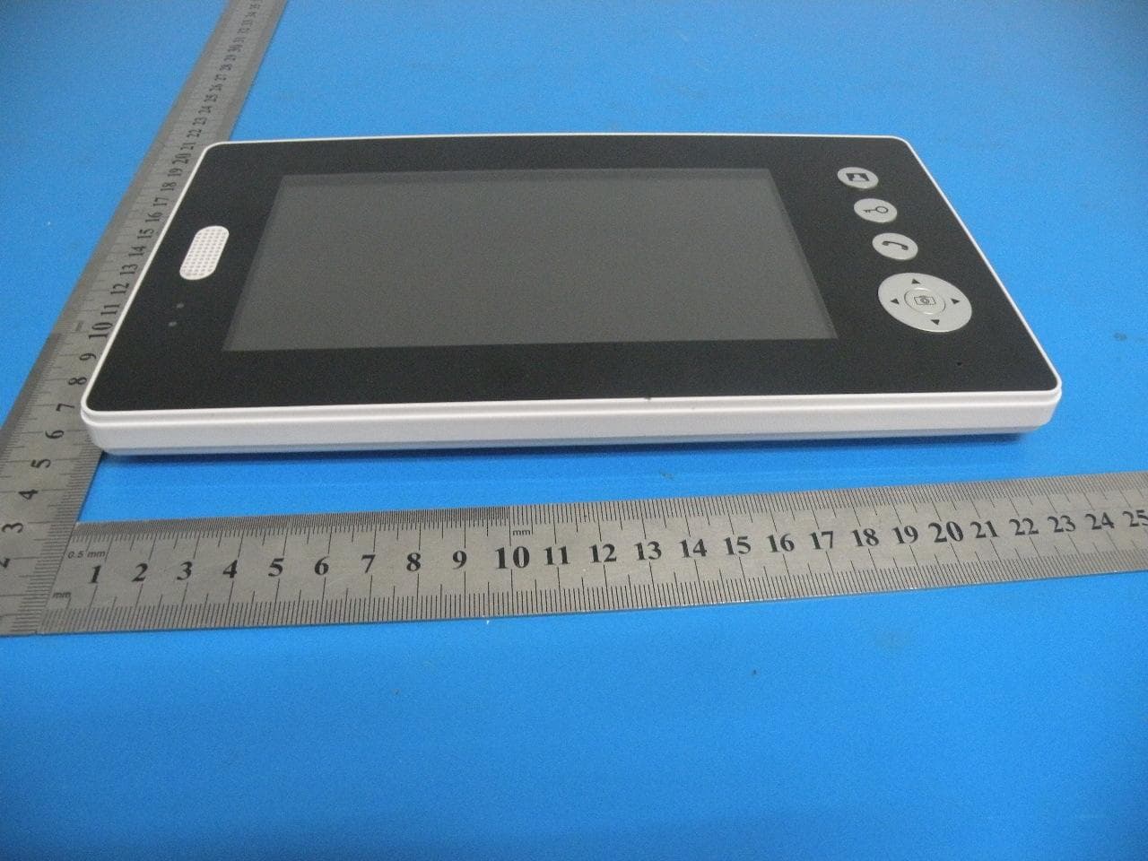
Click to zoom
Application Details
- Equipment Class
- DXX - Part 15 Low Power Communication Device Transmitter
- Date of Grant
- Nov 07, 2013
- Application Purpose
- Original Equipment
- Date of Application
- Nov 07, 2013
- Equipment Note
- Wireless video door phone (Indoor Monitor)
- Frequency Range
- 2402.00000000 - 2480.00000000
- Company
- KONX INTERNATION LIMITED
- Country
- China
Documents & Files
Document Text
Text extracted from the exhibit documents filed with the FCC. Open a document above to read the original.
Users Manual
Wireless Video Door Phone User Manual 1 Contents 1. Introduction ...................................................................... 2 2. Features ............................................................................ 2 3. Packing list ........................................................................ 3 4. Outdoor camera ................................................................. 4 5. Indoor monitor .................................................................. 4 6. Installation instructions ....................................................... 5 7. E-lock installation ................................................................ 7 8. Operation........................................................................... 8 9. Working environment .........................................................13 10. Notices ...........................................................................13 11. Specifications ..................................................................13 12. Failure diagnosis ..............................................................14 ● Thank you for purchasing our product. ● Please carefully read this us er manual before using the product and follow the manual to install and operate. 2 1. Introduction The product is applicable in office, house, apartment, hotel, building and so on. The outdoor camera is easy to install. Indoor monitor is portable. It can be hung on the wall, or be placed on the desk. 2. Features (1) 2.4GHz digital frequency hopping and encryption technology, transmission distance up to 200 meters in free field, robust anti-interference (2) Clear night vision can capture image in low-illumination environment (3) Rain shield for the outdoor camera is available (4) 3.5 or 7 inch TFT color panel for indoor monitor (5) Surveillance, unlock, hands-free call and talk (6) 16 chord melodies and melody volume is adjustable (7) Brightness and talk volume are adjustable (8) Date (only one camera with one monitor system) and time shown on the screen (9) Indoor monitor could take pictures auto matically or by instruction. It could store up to 100 pictures with date and time (10) BL-5J battery of camera and monitor is replaceable and rechargeable (11) Outdoor camera works about 30 days if with battery. It works all the while if connected with the 2w solar module. Or it works all the while if power adapter is connected. (12) Wireless unlock control supports power on and power off unlock (13) One outdoor camera supports up to 4 indoor monitors and vice versa 3 3. Packing list Outdoor camera part (1) Outdoor camera (2) Power adapter Input: 100-240V 50/60Hz Output: 5V/1A (3) double-sided tape (4) Unlock control (5) Screws and stoppers (6) DC cable (7) Remote control (optional) (8) BL-5J battery (optional) (9) Sloar moudle charger (optional) (10) 6meters or 10meters antenna Indoor monitor part (11) 3.5” indoor monitor or 7” indoor monitor (12) Fixed iron for 7” indoor monitor (13) BL-5J battery (14) USB Cable (15 ) USB power adapter; Input: 100-240V 50/60Hz Output: 5V/1A (16) User manual 4 4. Outdoor camera (1) Microphone (2) Camera lens (3) Rain shield (4) Infrared light (5) Indicating light for recharge (6) Indicating light, show green if press ‘pair’ or ‘call’ button, show red if low voltage (7) ‘Call’ button (8) Speaker (9) Adapter interface (10) ‘Pair’ button (11) Battery lid of BL-5J (12) Obligate area welding antenna 5. Indoor monitor (A) 3.5” indoor monitor 5 (B) 7” indoor monitor (1) Speaker (2) TFT screen (3) Antenna (4) Microphone (5) ‘Monitor’ button (6) ’Unlock’ button (7) ’Talk’ button (8) Left (9) ▼ Down (10) Right (11) charging light (12) Working light (13) ‘Take picture ’ button (14) ▲ Up (15) USB interface (16) Power switch (17) Fixed slot (18) Battery lid of BL-5J (19) Bracket 6. Installation instructions The outdoor camera should be installed at the shielded position to be free from direct shinning of strong light or rainin g. The height for installation is recommended to be 1.5~1.7m for outdoor camera to focus on the best monitoring range. Wireless signal will be weakened if there are obsta cles between the outdoor camera and the indoor monitor. Please check the best sign of monitor when install the outdoor camera to get the best position. 6 If wiring needs to go through wall, the plug should be firstly wrapped with tape so as to avoid the sand or dirt going into the plug thus resulting in malfunction. Use double-sided tape fix camera on the wall or door as the following diagram. Take off the screw on the bottom, remove the back box fit on the wall, embed the camera to the back box and use screws to fix as the following diagram. If it is inconvenient for the user to install power adapter near outdoor camera, user can also select solar panel module and rechargeable battery for outdoor camera. But the solar panel module and rechargeable battery are not included in the product package list. The Vmp and Imp of the 2w solar panel module are 5v and 400mA respectively. The wire between solar panel module and camera length is 6 meters. You’d better put the solar module on the place the sun can directly shine. The battery costs 3~4hours to be fully charged by strongly directly shinning. Outdoor camera can work about 30 days each full recharge. 7 7. E-lock installation E-lock and power of e-lock are not included in this product. Unlock control connects e-lock, shares 12V power ada pter with e-lock when it works. 8 Notes: The distances between wireless unlock control and outdoor camera should be within 10 meters so that the wireless unlock control is able to receive unlock command. The remote control uses 27A/12V battery. presses of remote control to unlock. The work distance between remote control and unlock control should be within 15 meters. The system can work together with inte lligent lock, Intelligent lock uses 4pcs AA batteries. 8. Operation Note: When the system is in working condition, if there is no blocking wall…
Text truncated - open the document above for the full version.
Cover Letter(s)
Differences Description We KONX INTERNATION LIMITED state: Product name: Wireless video door phone(Indoor Monitor) Model: KX7001, KX3501, PH3501, PH7001, KX7002, PH7002 All model’s the function, software and electric circuit are the same , only with a product color and model named different. Signatory Signature Date: 2013/10/26 Name: Kevin Nie Title: Engineer Tel: (86)-0755-61156588 Company: KONX INTERNATION LIMITED
Cover Letter(s)
KONX INTERNATION LIMITED SCS-F19: Confidentiality Request Letter Page 1 of 2 Rev 3.0 775 Montague Expressway Milpitas, CA 95035 Tel: 408-526-1188 Fax: 408-526-1088 Email: [email protected] Confidentiality Request Letter Reason for Amendment (current / obsolete) Revision History Approved Date From To Initial Release (obsolete) 1.0 1.0 Nov-14-2006 Adding CFR 2.459 (obsolete) 1.0 2.0 August – 11 - 2008 Updated company template & Added text box (current) 2.0 3.0 Jan-31-2012 KONX INTERNATION LIMITED SCS-F19: Confidentiality Request Letter Page 2 of 2 Rev 3.0 2013/10/26 To: Federal Communications Commission Authorization and Evaluation Division 7435 Oakland Mills Road Columbia, MD Subject: Permanent Confidentiality Request for FCC ID: 2AA6JKXPH We hereby request confidential treatment of information accompanying this application as outlined below: - Block Diagram - Schematics - Operational Description The above materials contain trade secrets and proprietary information not customarily released to the public. The public disclosure of these materials may be harmful to the applicant and provide unjustified benefits to its competitors. The applicant understands that pursuant to Section 0.457 & 0.459 of the Rules, disclosure of this application and all accompanying documentation will not be made before the date of the Grant for this application. Sincerely, Client’s signature Signature Date: 2013/10/26 Name: Kevin Nie Title: Engineer Tel: (86)-0755-61156588 Company: KONX INTERNATION LIMITED
External Photos
Full View Top View Bottom View Bottom View Rear View Left View Right View Front View
ID Label/Location Info
Label: Label Location FCC ID: 2AA6JKXPH KONX INTERNATION LIMITED Model No.: KX7001 Model name: Wireless video door phone(Indoor Monitor) This device complies with Part 15 of the FCC Rules. Operation is subject to the following two conditions: (1) this device may not cause harmful interference, and (2) this device must accept any interference received, including interference that may cause undesired operation.
Internal Photos
Top View Top View Antenna Top View Bottom View Top View Top View Top View Bottom View Top View Bottom View
Test Report
FCC RADIO TEST REPORT FCC ID: 2AA6JKXPH Product: Wireless video door phone (Indoor Monitor) Trade Name: KONX Model Name: KX7001, KX3501, PH3501, PH7001, KX7002, PH7002 Serial Model: N/A Report No.: BZT-2013NT1021070F Prepared for KONX INTERNATION LIMITED Floor 2, Block A, Yili Science & Technology Park, Huan Guan South Road, Guanlan Town, Long Hua District, ShenZhen GuangDong, China Prepared by BZT Testing Technology Co., Ltd. 1/F, Building E, Fenda Science Park, Sanwei Community, Xixiang Street, Bao’an District, Shenzhen P.R. China Page 2 of 40 Report No.: BZT131021070F ` TEST RESULT CERTIFICATION Applicant’s name ................. : KONX INTERNATION LIMITED Address ................................. : Floor 2, Block A, Yili Science & Technology Park, Huan Guan South Road, Guanlan Town, Long Hua District, ShenZhen GuangDong, China Manufacture's Name ............ : KONX INTERNATION LIMITED Address ................................. : Floor 2, Block A, Yili Science & Technology Park, Huan Guan South Road, Guanlan Town, Long Hua District, ShenZhen GuangDong, China Product description Product name............................ : Wireless video door phone(Indoor Monitor) Model and/or type reference : KX7001, KX3501, PH3501, PH7001, KX7002, PH7002 Serial Model: N/A Rating(s) ................................ : DC 3.7V from battery or DC 5V from adapter with AC 120V/60Hz Standards ............................. : FCC Part15.249 Test procedure ............................... : ANSI C63.4-2003 This device described above has been tested byBZT, and the test results show that the equipment under test (EUT) is in compliance with the FCC requirements. And it is applicable only to the tested sample identified in the report. This report shall not be reproduced except in full, without the written approval ofBZT, this document may be altered or revised byBZT, personal only, and shall be noted in the revision of the document. Date of Test ........................................... : Date (s) of performance of tests ............. : 16 October. 2013 ~22 October. 2013 Date of Issue .......................................... : 23 October. 2013 Test Result.............................................. : Pass Testing Engineer : (Apple Huang) Technical Manager : (Tom Zhang) Authorized Signatory : (Bovey Yang) Page 3 of 40 Report No.: BZT131021070F ` Table of Contents Page 1 . SUMMARY OF TEST RESULTS 4 1.1 TEST FACILITY 5 1.2 MEASUREMENT UNCERTAINTY 5 2 . GENERAL INFORMATION 6 2.1 GENERAL DESCRIPTION OF EUT 6 2.2 DESCRIPTION OF TEST MODES 8 2.3 BLOCK DIGRAM SHOWING THE CONFIGURATION OF SYSTEM TESTED 9 2.4 DESCRIPTION OF SUPPORT UNITS(CONDUCTED MODE) 10 2.5 EQUIPMENTS LIST FOR ALL TEST ITEMS 11 3 . ANTENNA REQUIREMENT 12 3.1 STANDARD REQUIREMENT 12 3.2 EUT ANTENNA 12 3.3 CONDUCTED EMISSION MEASUREMENT 13 3.3.1 POWER LINE CONDUCTED EMISSION LIMITS 13 3.3.2 TEST PROCEDURE 14 3.3.3 DEVIATION FROM TEST STANDARD 14 3.3.4 TEST SETUP 14 3.2.5 TEST RESULT 15 3.4 RADIATED EMISSION MEASUREMENT 17 3.4.1 RADIATED EMISSION LIMITS 17 3.4.2 TEST PROCEDURE 18 3.4.3 DEVIATION FROM TEST STANDARD 18 3.4.4 TEST SETUP 19 3.4.5 TEST RESULTS (BLOW 30MHZ) 21 3.4.6 TEST RESULTS (BETWEEN 30 – 1000 MHZ) 22 3.4.7 TEST RESULTS (ABOVE 1000 MHZ) 24 3.4.8 TEST RESULTS (RESTRICTED BANDS REQUIREMENTS) 27 4 . BANDWIDTH TEST 35 4.1 TEST PROCEDURE 35 4.2 DEVIATION FROM STANDARD 35 4.3 TEST SETUP 35 4.4 TEST RESULTS 36 5 . EUT TEST PHOTO 39 APPENDIX-PHOTOGRAPHS OF EUT CONSTRUCTIONAL DETAILS Page 4 of 40 Report No.: BZT131021070F ` 1. SUMMARY OF TEST RESULTS Test procedures according to the technical standards: FCC Part15, Subpart C (15.249) Standard Section Test Item Judgment Remark 15.207 Conducted Emission Pass 15.203 Antenna Requirement Pass 15.249 Radiated Spurious Emission Pass 15.205 Band Edge Emission Pass 15.249 Occupied Bandwidth Pass NOTE: (1)” N/A” denotes test is not applicable in this Test Report Page 5 of 40 Report No.: BZT131021070F ` 1.1 TEST FACILITY BZT Testing Technology Co., Ltd Add. : 1/F, Building E, Fenda Science Park, Sanwei Community, Xixiang Street, Bao’an District, Shenzhen P.R. China. FCC Registered No.: 701733 1.2 MEASUREMENT UNCERTAINTY The reported uncertainty of measurement y ± U,where expended uncertainty U is based on a standard uncertainty multiplied by a coverage factor of k=2,providing a level of confidence of approximately 95 %。 No. Item Uncertainty 1 Conducted Emission Test ±1.38dB 2 RF power,conducted ±0.16dB 3 Spurious emissions,conducted ±0.21dB 4 All emissions,radiated(<1G) ±4.68dB 5 All emissions,radiated(>1G) ±4.89dB 6 Temperature ±0.5°C 7 Humidity ±2% Page 6 of 40 Report No.: BZT131021070F ` 2. GENERAL INFORMATION 2.1 GENERAL DESCRIPTION OF EUT Equipment Wireless video door phone(Indoor Monitor) Trade Name KONX Model Name KX7001, KX3501, PH3501, PH7001, KX7002, PH7002 Serial Model N/A Model Difference All model’s the function, software and electric circuit are the same, only with a product color and model named different, test mode is KX7001. Product Description The EUT is a Wireless video door phone(Indoor Monitor) Operation Frequency: 2402~2480MHz Modulation Type: GFSK Antenna Designation: Internal antenna Antenna Gain(Peak) 1.25 dBi EIRP 90.15 dbuv/m@3m Based on the application, features, or specification exhibited in User's Manual, the EUT is considered as an ITE/Computing Device. More details of EUT technical specification, please refer to the User's Manual. Channel List Please refer to the Note 2. Adapter Output: DC 5V Battery DC 3.7V Note: 1. For a more detailed features description, please refer to the manufacturer’s specifications or the User's Manual. Page 7 of 40 Report No.: BZT131021070F ` 2. Channel List Channel Frequency (MHz) Channel Frequency (MHz) Channel Frequency (MHz) 01 2402 28 2429 55 2456 02 2403 29 2430 56 2457 03 2404 30 2431 57 2458 04 2405 31 2432 58 2459 05 2406 32 2433 59 2460 06 2407 33 2434 60 2461 07 2408 34 2435 61 2462 08 2409 35 2436 62 2463 09 2410 36 2437 63 2464 10 2411 37…
Text truncated - open the document above for the full version.
Test Setup Photos
Radiated Emission Test Setup in Chamber Conducted Emission Test Setup in Chamber
Contact Information
Applicant
Kevin Nie(Engineer)
Test Firm
BZT Testing Technology Co., Ltd.Bruce Zhang
Technical Specifications
| # | Rule Parts | Frequency Range | Power Output |
|---|---|---|---|
| 1 | 15C | 2.40 GHz - 2.48 GHz | - |
Other Applications from KONX INTERNATION LIMITED
2AA6J-AHD7
Apr 06, 2022Video Door Phone
Equipment Class
DTS - Digital Transmission System