2AA7CCONNREFGBud-e fridge
Fandom Connect Operating Pty Ltd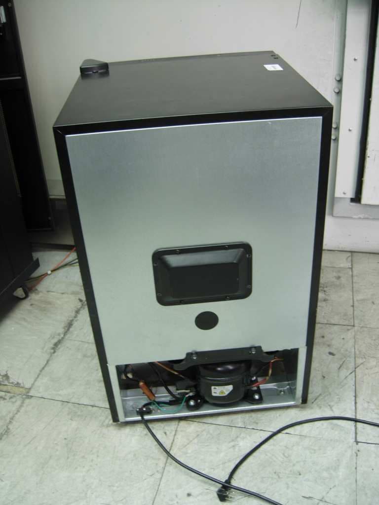
Click to zoom
Application Details
- Equipment Class
- DSC - Part 15 Security/Remote Control Transmitter
- Date of Grant
- Mar 22, 2015
- Application Purpose
- Original Equipment
- Date of Application
- Mar 19, 2015
- Equipment Note
- Bud-e fridge
- Frequency Range
- 433.92000000 - 433.92000000
- Country
- Australia
Documents & Files
Document Text
Text extracted from the exhibit documents filed with the FCC. Open a document above to read the original.
Users Manual
1. Bud-e FRIDGE – USER GUIDE 2. NOTES BEFORE INSTALLATION 1. Allow unit to rest upright in the correct position for 1 hour before unboxing. 3. Position unit in a well ventilated area and ensure you allow a minimum of 2 inches clear area around the unit. 4. Do not rest any objects on the top or sides of the unit 5. The fridge requires a 110V US type power outlet. 6. After turning the fridge on allow it to reach pre-programmed temperature (0°C/32°F) (3 LEDs on) over a 12 hour period. 7. After this initial period (minimum 12 hours) the fridge setting can be changed to achieve below zero temperatures by illuminating all 5 LEDS’s (-1.5°C/-3.0°C) or (29°F/26°F) 8. To ensure the unit can reach below zero temperatures efficiently, please load with cold beer as opposed to room temperature product where possible. 9. It is normal for the sides of the fridge to be warm at times during operation. UNBOXING YOUR Bud-e FRIDGE Move packaged unit to approximate position of installation and allow unit to rest upright in the correct position for 1 hour before unboxing. 1.2. Cut the straps and slide the complete cardboard outer upward and off the fridge. Remove the fridge from the packaging base. Place the fridge in position on a level surface near a 110V power outlet. Remove any plastic coverings from the fridge Cut 3. UNBOXING YOUR Bud-e FRIDGE 3. 5. 4. Open fridge door and remove all internal packaging and tape. Plug the fridge into a 110V power outlet. Insert one ‘colour roller’ per channel ensuring silver magnetic feet are facing down as shown. Shelf channels Remove packaging Remove tape Remove packaging x 18 32 4. CONNECTING Bud-e TO WI-FI Before connecting to Wi-Fi you will need Bud-e FRIDGE TEMPERATURE SETTINGS The fridge has 5 temperature settings*: 1 LED on = 5°C = 41°F 2 LEDs on = 2°C = 35°F 3 LEDs on = 0°C (default) = 32°F 4 LEDs on = -1.5°C = 29°F 5 LEDs on = -3.0°C = 27°F *Please note these are approximate temperature settings only. Actual temperature may differ depending on stock and environment. An iOS or Android mobile device Warning • This product will not connect to any Wi-Fi networks requiring secondary authentication. • Make sure your phone is connected to the Wi-Fi network you wish to connect your fridge to. • For best ‘blinkup’ results turn your iPhone screen to maximum brightness. • For best ‘blinkup’ results do not place fridge in direct sunlight or where there may be bright or flashing lights. Download the Bud-e APP and follow on screen prompts to connect Wi-Fi router - 802.11b/g/n with broadband internet connection. Temperature settings are located on top of the fridge door. 23451 1.2. 3. Wi-Fi 5. Shelf channels Bud-e WI-FI STATUS LED (top panel) Wi-Fi LED status Flashing red = not connected Flashing green = connected successfully Solid green = updating firmware (do not unplug fridge during this process) Flashing amber = has not received any Wi-Fi settings Off = normal operation (the unit is still connected to Wi-Fi) Note: If the unit loses its Wi-Fi connection the Wi-Fi icon on the display will also flash red. Wi-Fi status LED is located on top of the fridge door. LOADING AND UNLOADING STOCK INTO Bud-e FRIDGE Please note the top two shelves of this fridge are designed for US type 12oz bottles, 12oz cans, or 16oz cans only. Please note, the bottom shelf is for 12oz cans only. 1.2. Make sure there is a ‘colour roller’ in each channel. Push base of bottle or can in direction shown making sure it pushes the colour roller further back into the shelf channel. 6. LOADING AND UNLOADING STOCK INTO Bud-e FRIDGE 3. Make sure roller is directly behind bottle or can for accurate stock counting. 4. 5. On closing the fridge door the stock levels will be displayed on the door for 5 seconds and then display the current fridge internal temperature. The colour rollers measure the stock level. When removing beer make sure the colour roller slides as far towards the door as possible. Stock countTemperature 7. Bud-e FRIDGE STOCK CAPACITY Please note: The bottom shelf of the Bud-e fridge will hold cans only The total capacity of the Bud-e fridge is 78 vessels. This will be made up of either all cans or cans and bottles. Total bottle capacity is 60 bottles Cans only Cans only x 30 x 30 x 18 Total 78 or or 8. Bud-e APP - Wi-Fi CONNECTION Download the Bud-e APP and follow on screen prompts to connect 1. 3. 2. 4. Let’s go Bud-e Facebook Name Password Bud-e Let me in Bud-e Territory MM / DD / YYYY Old enough to share a Bud? You must be of legal drinking age to access Bud-e Set up my Bud-e What’s a Bud-e? Bud-e Activate Bud-e via Signing up means you agree to our Terms and Conditions Signing up means you agree to our Terms and Conditions Facebook not for you? Bud-e HELP Activate Bud-e via Or create a Bud-e account Facebook We never post to your wall We never post to your wall Twitter Google + Activate with Email Address 1Loading screen23A4A Let’s go Bud-e Twitter Name Password 4B 3B Let’s go Bud-e Google + Name Password 4C Let’s go Bud-e Name Email Phone 4D Create Bud-e account User has the option to see what the Bud-e fridge is all about. This is a crucial area to grab possible sales from people who have just downloaded the app because it’s a Budweiser app and not because they have a fridge. See screen 21 Sign in through Facebook is our preferred option Other sign in options are available if not Facebook Let’s go Bud-e Facebook Name Password Bud-e Let me in Bud-e Territory MM / DD / YYYY Old enough to share a Bud? You must be of legal drinking age to access Bud-e Set up my Bud-e What’s a Bud-e? Bud-e Activate Bud-e via Signing up means you agree to our Terms and Conditions Signing up means you agree to our Terms and Conditions Facebook not for you? Bud-e HELP Activate Bud-e via Or create a Bud-e account Facebook We never post to your wall We never post to your wall Twitter Google + Activate with Email Address 1Loading screen23A4A Let’s go Bud-e Twitter Name Password 4B 3B Let’s go Bud-e Google + Name Passwor…
Text truncated - open the document above for the full version.
Users Manual
Bud-e fridge 010275 Save this manual You will need this manual for safety instructions, operating procedures and warranty. Put it and the original sales invoice in a safe, dry place for future reference. SAFETY PRECAUTIONS Read all of the instructions before using this appliance. When using this appliance, always exercise basic safety precautions, including the following: NOTE: If the refrigerator has been placed in a horizontal or tilted position for any period of time wait 24 hours before plugging the unit in. 1) Use this appliance only for its intended purpose as described in this use and care guide. 2) This refrigerator must be properly installed in accordance with the installation instructions before it is used. See grounding instructions in the installation section. 3) Never unplug your refrigerator by pulling on the power cord. Always grasp the plug firmly and pull straight out from the outlet. 4) Repair or replace immediately, all electric service cords that have become frayed or otherwise damaged. Do not use a cord that shows cracks or abrasion damage along its length, the plug or the connector end. 5) Unplug your refrigerator before cleaning or before making any repairs. Note: If for any reason this product requires service, we strongly recommend that a certified technician performs the service. 6) Do not use any electrical device or any sharp instrument in defrosting your refrigerator. 7) If your old refrigerator is not being used, we recommend that you remove the doors and leave the shelves in place. This will reduce the possibility of danger to children. 8) After your refrigerator is in operation, do not touch the cold surfaces in the freezer compartment, particularly when hands are damp or wet. Skin may adhere to these extremely cold surfaces. 9) This refrigerator should not be recessed or built-in in an enclosed cabinet. It is designed for freestanding installation only. 10) Do not operate your refrigerator in the presence of explosive fumes. SAVE THESE INSTRUCTIONS DANGER Risk of child entrapment. Before you throw away your old refrigerator or freezer, take off the doors. Leave the shelves in place so that children may not easily climb inside. Installing Your Refrigerator Unpacking Your Refrigerator 1. Remove all packaging material. This includes the foam base and all adhesive tape holding the refrigerator accessories inside and outside. 2. Inspect and remove any remains of packing, tape or printed materials before powering on the refrigerator. Leveling Your Refrigerator • Your refrigerator has two leveling legs which are located in the front bottom corners of your refrigerator. After properly placing your refrigerator in its final position, you can level your refrigerator. • Leveling legs can be adjusted by turning them clockwise to raise your refrigerator or by turning them counterclockwise to lower your refrigerator. The refrigerator door will close easier when the leveling legs are extended. Proper Air Circulation • To ensure your refrigerator works at the maximum efficiency it was designed for, you should install it in a location where there is proper air circulation, plumbing and electrical connections. • The following are recommended clearances around the refrigerator: Sides...............3/4” (19mm) Top....................2” (50mm) Back..................2” (50mm) Electrical Requirements • Make sure there is a suitable power outlet with proper grounding to power the refrigerator. • Avoid the use of three prong adapters or cutting off the third grounding prong in order to accommodate a two prong outlet. This is a dangerous practice since it provides no effective grounding for the refrigerator and may result in shock hazard. Use of Extension Cords • Avoid the use of an extension cord because of potential safety hazards under certain conditions. If it is necessary to use an extension cord, use only a 3-wire extension cord that has a 3-blade grounding plug and a 3-slot outlet that will accept the plug. The marked rating of the extension cord must be equal to or greater than the electrical rating of the appliance. Installation Limitations • Do not install your refrigerator in any location not properly insulated or heated, e.g. garage, etc. Your refrigerator was not designed to operate in temperature settings below 55 ̊ Fahrenheit / 12 ̊ Celsius. • Select a suitable location for the refrigerator on a hard even surface away from direct sunlight or heat source, e.g. radiators, baseboard heaters, cooking appliances, etc. Any floor unevenness should be corrected with the leveling legs located on the front bottom corners of the refrigerator. In addition to the sounds from the amplified speaker, normal operating sounds you may hear • Boiling water, gurgling sounds or slight vibrations are the result of the refrigerant circulating through the cooling coils. • The thermostat control will click when it cycles on and off. Proper Refrigerator Care and Cleaning Cleaning and Maintenance Warning: To avoid electric shock, always unplug your refrigerator before cleaning. Ignoring this warning may result in death or injury. Caution: Before using cleaning products, always read and follow manufacturer’s instructions and warnings to avoid personal injury or product damage. General: Wipe down your refrigerator with a damp cloth, do not expose the internals to any liquids. • Dry with a soft cloth. • Do not use harsh chemicals, abrasives, ammonia, chlorine bleach, concentrated detergents, solvents or metal scouring pads. Some of these chemicals may dissolve, damage and/ or discolour your refrigerator. Door Gaskets: Clean door gaskets every three months according to general instructions. Gaskets must be kept clean and pliable to ensure a proper seal. • Petroleum jelly applied lightly on the hinge side of gaskets will keep the gasket pliable and ensure a good seal. Power Interruptions • Occasionally there may be power interruptions due to thunderstorms or other causes. Remove the power cord from…
Text truncated - open the document above for the full version.
Cover Letter(s)
LetterOfGuarantee We,NingboHiconInternationalIndustryCo.,Ltdcertifybelow: FortheproductBud-efridgewithmodel010275,anymodificationsofallelectricaland mechanicaldevicesaboutradiationsuppressionmadeduringcertificationtestinginIntertekTesting ServicesShanghaiLimited,willbeincorporatedineachunitofourmassproduction. Yoursfaithfully, Companyrepresentative:Maobinjun Company:NingboHiconInternationalIndustryCo.,Ltd 2015-03-17 PDF created with pdfFactory Pro trial version www.pdffactory.com
External Photos
FCC ID: 2AA7CCONNREFG IC: 11838A-CONNREFG Page 1 of 1 External Picture
ID Label/Location Info
Bud-E Fridge Model:010275 FCC ID:2AA7CCONNREFG IC:11838A-CONNREFG Contains FCC ID:PPQ-IMP002 Contains IC:4491A-IMP002 This device complies with Part 15 of the FCC Rules / Industry Canada licence-exempt RSS standard(s). Operation is subject to the following two conditions: (1) this device may not cause harmful interference, and (2) this device must accept any interference received, including interference that may cause undesired operation. Label position
Internal Photos
FCC ID: 2AA7CCONNREFG IC: 11838A-CONNREFG Page 1 of 5 Internal Picture Switch power board FCC ID: 2AA7CCONNREFG IC: 11838A-CONNREFG Page 2 of 5 Led panel FCC ID: 2AA7CCONNREFG IC: 11838A-CONNREFG Page 3 of 5 FCC ID: 2AA7CCONNREFG IC: 11838A-CONNREFG Page 4 of 5 433MHz Module FCC ID: 2AA7CCONNREFG IC: 11838A-CONNREFG Page 5 of 5 Antenna
RF Exposure Info
©2013 A Test Lab Techno Corp. Report Number: 1302FS12Page 1 of 5 A Test Lab Techno Corp. Changan Lab:No. 140 -1, Changan Street, Bade City, Taoyuan County, Taiwan R.O.C. Te l:886-3-271-0188 / Fax:886-3-271-0190 MPE Report Test Report No. : 1302FS12 Applicant : LITE-ON TECHNOLOGY CORP. Manufacturer : electric imp, inc. Product Type : imp Trade Name : electric imp Model Number : IMP002 Date of Received : Feb. 05, 2013 Test Period : Mar. 08, 2013 Date of Issued : Mar. 13, 2013 Test Specification : 47 CFR § 2.1091 47 CFR §1.1310 ANSI / IEEE Std.C95.1-1992 H46-2/99-237E Location of Test Lab. : Chang-an Lab. 1. The test operations have to be performed with cautious behavior, the test results are as attached. 2. The test results are under chamber environment of A Test Lab Techno Corp. A Test Lab Techno Corp. does not assume responsibility for any conclusions and generalizations drawn from the test results with regard to other specimens or samples. 3. The measurement report has to be written approval of A Test Lab Techno Corp. It may only be reproduced or published in full. This report shall not be reproduced except in full, without the written approval of A Test Lab Techno Corp. 4. This document may be altered or revised by A Test Lab Techno. Corp. personnel only, and shall be noted in the revision section of the document. Approved By : Tested By : (Yung Tan Tsai ) (Bill Hu) Contents 1. Description of Equipment under Test (EUT) ............................................................... 3 2. Human Exposure Assessment..................................................................................... 4 3. RF Output Power........................................................................................................... 5 4. Test Result .....................................................................................................................5 ©2013 A Test Lab Techno Corp. Report Number: 1302FS12Page 2 of 5 ©2013 A Test Lab Techno Corp. Report Number: 1302FS12Page 3 of 5 1. Description of Equipment under Test (EUT) Applicant LITE-ON TECHNOLOGY CORP. Applicant Address 4F, 90, Chien 1 Road, Chung Ho, Taipei Hsien 235, Taiwan, R.O.C. Manufacturer electric imp, inc. Manufacturer Address 5050 EI Camino Real, STE 221, Los Altos, CA94022, USA Product Type imp Trade Name electric imp Model Number IMP002 FCC ID PPQ-IMP002 IC 4491A-IMP002 Frequency Range IEEE 802.11b / IEEE 802.11g / 802.11n 2.4GHz (20MHz): 2412 ~ 2462 MHz Transmit Power IEEE 802.11 b: 0.037 W / 15.74 dBm (AVG. Conducted Power) IEEE 802.11 g: 0.019 W / 12.89 dBm IEEE 802.11n 2.4GHz (20MHz): 0.014 W / 11.61 dBm Antenna used Manufacturer Model Number Antenna Type Antenna Gain MAG.LAYERS SCIENTIFIC-TECHNICS EDA-8709-2G4R2-A37 External Antenna 2.00 dBi Lite-On Technology Corp.none PIFA Antenna 2.86 dBi Temperature Range -30 ~ +70°C The above equipment was tested by A Test Lab Techno Corp. For compliance with the requirements set forth in 47 CFR § 2.1091 & 47 CFR § 1.1310. The results of testing in this report apply only to the product/system, which was tested. Other similar equipment will not necessarily produce the same results due to production tolerance and measurement uncertainties 2. Human Exposure Assessment Due to the design and installation of this product, it is not possible to conduct SAR evaluation. This is because client either manufactures or supplies the antenna(s) that will be used in the installation of this product. Therefore, this product will be evaluated as a mobile device per 47 CFR §1.1310 titled “Radiofrequency radiation exposure limits”, generally referred to as MPE limits. In 47 CFR § 2.1091, paragraph (b) defines a mobile device as “a transmitting device designed to be used in other than fixed locations and to generally be used in such a way that a separation distance of at least 20 cm is normally maintained between the transmitter’s radiating structure(s) and the body of the user or nearby persons. ” This product is intended to be installed into a vehicle such that the unit is physically secured at one location. In the installation guide supplied with the product, Client has made the following statement: “IMPORTANT: To meet the FCC’s RF Exposure Guidelines, the antenna should be installed so there is at least 20 cm of separation between the body of the user and nearby persons and the antenna”. Based on the installation of the transceiver and the antenna, the transmitters radiating structure is more than 20 cm from the user. Thus, this product is a “mobile device” as defined in section § 2.1091 paragraph (b). Exposure evaluation Equation from page 18 of OET Bulletin 65, Edition 97-01 2 4R PG S π = Where S: power density P: power input to the antenna G: power gain of the antenna in the direction of interest relative to an isotropic radiator. R: distance to the center of radiation of the antenna. Note: For evaluated 2G system, the transmission power P + G should be consider duty cycle. ©2013 A Test Lab Techno Corp. Report Number: 1302FS12Page 4 of 5 3. RF Output Power Conducted power (dBm) Band Date Rate CH Frequency (MHz) Avg. Peak Worst Case 01 2412 15.40 19.24 □ 06 2437 15.54 19.26 □ IEEE 802.11b 1 M 11 2462 15.74 19.32 ■ 01 2412 12.66 22.31 □ 06 2437 12.82 22.51 □ IEEE 802.11g 6 M 11 2462 12.89 22.56 ■ 01 2412 11.40 22.13 □ 06 2437 11.41 22.20 □ IEEE 802.11n 2.4GHz (20MHz) 6.5 M 11 2462 11.61 22.25 ■ 4. Test Result Band Data Rate Frequency (MHz) Limit (mw/cm 2 ) Distance [R] (cm) Tune-up power [P] (dBm) ANT Gain [G] (dBi) [P]+ [G] [TP] (W) Duty Cycle [TP] with duty cycle (W) Power Density [S] (mw/cm 2 ) Min. distance (cm) 2412 1.000 20 18.00 2.86 0.122 1 0.122 0.024 20cm 2437 1.000 20 18.00 2.86 0.122 1 0.122 0.024 20cm IEEE 802.11b 1 M 2462 1.000 20 18.00 2.86 0.122 1 0.122 0.024 20cm 2412 1.000 20 15.50 2.86 0.069 1 0.069 0.014 20cm 2437 1.000 20 15.50 2.86 0.069 1 0.069 0.014 20cm IEEE 802.11g 6 M 2462 1.000 20 15.50 2.86 0.069 1 0.069 0.014 20cm 2412 1.000 20 14.25 2.86 0.051 1 0.051 0.010 …
Text truncated - open the document above for the full version.
Test Report
FCC ID: 2AA7CCONNREFG IC: 11838A-CONNREFG Page 1 of 21 EMC TEST REPORT No. 150100700SHA-001 Applicant : Buzz Products PTY LTD 18 Studley Street Abbotsford Victoria Australia 3067 Manufacturer : Ningbo Hicon International Industry Co.,Ltd No.55,4 th Binhai Road,Hangzhou Bay New Zone,Cixi,Ningbo,Zhejiang Province 315336 . Equipment : Bud-e fridge Type/Model : 010275 SUMMARY The equipment complies with the requirements according to the following standard(s): 47CFR Part 15 (2014): Radio Frequency Devices ANSI C63.4 (2003): American National Standard for Methods of Measurement of Radio-Noise Emissions from Low-Voltage Electrical and Electronic Equipment in the Range of 9 kHz to 40 GHz RSS-210 Issue 8 (December 2010): Low-power Licence-exempt Radio communication Devices (All Frequency Bands): Category I Equipment RSS-Gen Issue 4 (November 2014): General Requirements for Compliance of Radio Apparatus Date of issue: Feb 28, 2015 Prepared by: Reviewed by: Jesse Xu (Project Engineer) Daniel Zhao (Reviewer) FCC ID: 2AA7CCONNREFG IC: 11838A-CONNREFG Page 2 of 21 Description of Test Facility Name: Intertek Testing Services Limited Shanghai Address: Building No.86, 1198 Qinzhou Road(North), Shanghai 200233, P.R. China FCC Registration Number: 236597 IC Assigned Code: 2042B-1 Name of contact: Steve Li Tel: +86 21 64956565 ext. 214 Fax: +86 21 54262335 ext. 214 FCC ID: 2AA7CCONNREFG IC: 11838A-CONNREFG Page 3 of 21 Content SUMMARY .......................................................................................................................................................... 1 DESCRIPTION OF TEST FACILITY ......................................................................................................................... 2 1. GENERAL INFORMATION ............................................................................................................................ 4 1.1 Applicant Information ..................................................................................................... 4 1.2 Identification of the EUT ................................................................................................ 4 1.3 Technical specification ................................................................................................... 5 1.4 Mode of operation during the test / Test peripherals used .............................................. 5 2. TEST SPECIFICATION .................................................................................................................................. 6 2.1 Instrument list ................................................................................................................. 6 2.2 Test Standard .................................................................................................................. 6 3. FUNDAMENTAL & SPURIOUS EMISSION & RESTRICT BAND RADIATED EMISSION ................................... 8 3.1 Test limit ......................................................................................................................... 8 3.2 Test Configuration .......................................................................................................... 9 3.3 Test procedure and test setup .......................................................................................... 9 3.4 Test protocol ................................................................................................................. 10 4. DEACTIVATING TIME ................................................................................................................................ 12 4.1 Test limit ....................................................................................................................... 12 4.2 Test Configuration ........................................................................................................ 13 4.3 Test procedure and test setup ........................................................................................ 13 4.4 Test protocol ................................................................................................................. 13 5. POWER LINE CONDUCTED EMISSION ........................................................................................................ 14 5.1 Limit .............................................................................................................................. 14 5.2 Test configuration ......................................................................................................... 14 5.3 Test procedure and test set up ....................................................................................... 15 5.4 Test protocol ................................................................................................................. 16 6. EMISSION BANDWIDTH ............................................................................................................................. 18 6.1 Test limit ....................................................................................................................... 18 6.2 Test Configuration ........................................................................................................ 18 6.3 Test procedure and test setup ........................................................................................ 18 6.4 Test protocol ................................................................................................................. 19 7. OCCUPIED BANDWIDTH ............................................................................................................................ 20 7.1 Test limit ....................................................................................................................... 20 7.2 Test Configuration ........................................................................................................ 20 7.3 Test procedure and test setup ............................................…
Text truncated - open the document above for the full version.
Test Report
FCC ID: 2AA7CCONNREFG IC: 11838A-CONNREFG Page 1 of 11 Test Data FCC ID: 2AA7CCONNREFG IC: 11838A-CONNREFG Page 2 of 11 1. Fundamental & Spurious Emission & Restrict band radiated emission Horizontal 30-1000MHz 0 0 10 10 20 20 30 30 40 40 50 50 60 60 70 70 80 80 Level [dBμV/m] Level [dBμV/m] 30M 30M 50M 50M 70M 70M 100M 100M 200M 200M 300M 300M 500M 500M 700M 700M 1G 1G Frequency [Hz] Frequency [Hz] x x x x x x x x x x x x x x x x x x x x x x MES 150204H5_red MES 150204H5_red MES 150204H5_pre MES 150204H5_pre LIM FCC 15 F 3 QP Field Strength QP LIM FCC 15 F 3 QP Field Strength QP FCC ID: 2AA7CCONNREFG IC: 11838A-CONNREFG Page 3 of 11 Horizontal 1000-5000 MHz WIFI signal 0 10 20 30 40 50 60 70 80 Level [dBμV/m] 1G2G3G4G5G Frequency [Hz] x x x x x x MES 150204H9_red MES 150204H9_pre LIM FCC 15 F 3 PK Field Strength QP LIM FCC 15 F 3 AV Field Strength QP FCC ID: 2AA7CCONNREFG IC: 11838A-CONNREFG Page 4 of 11 Vertical 30-1000MHz 0 10 20 30 40 50 60 70 80 Level [dBμV/m] 30M50M70M100M 200M300M500M 700M 1G Frequency [Hz] x x x x x x x x x x x MES 150204V5_red MES 150204V5_pre LIM FCC 15 F 3 QP Field Strength QP FCC ID: 2AA7CCONNREFG IC: 11838A-CONNREFG Page 5 of 11 Vertical 1000-5000MHz WIFI signal 0 20 40 60 80 100 Level [dBμV/m] 1G2G3G4G5G Frequency [Hz] x x x x x MES 150204V9_red MES 150204V9_pre LIM FCC 15 F 3 PK Field Strength QP LIM FCC 15 F 3 AV Field Strength QP FCC ID: 2AA7CCONNREFG IC: 11838A-CONNREFG Page 6 of 11 2. Deactivating time FCC ID: 2AA7CCONNREFG IC: 11838A-CONNREFG Page 7 of 11 3. Emission bandwidth FCC ID: 2AA7CCONNREFG IC: 11838A-CONNREFG Page 8 of 11 4. Occupied bandwidth FCC ID: 2AA7CCONNREFG IC: 11838A-CONNREFG Page 9 of 11 5. Duty Cycle FCC ID: 2AA7CCONNREFG IC: 11838A-CONNREFG Page 10 of 11 FCC ID: 2AA7CCONNREFG IC: 11838A-CONNREFG Page 11 of 11 The test data with maximum duty cycle was listed above. The worst Duty cycle= (0.5*5+ 4.3) / 69.6 = 0.098
Test Setup Photos
FCC ID: 2AA7CCONNREFG IC: 11838A-CONNREFG Page 1 of 3 Test Setup FCC ID: 2AA7CCONNREFG IC: 11838A-CONNREFG Page 2 of 3 1. Radiated Emission 30MHz-1000MHz Higher than 1GHz FCC ID: 2AA7CCONNREFG IC: 11838A-CONNREFG Page 3 of 3 2. Conducted Emission
Contact Information
Applicant
Janet Gibson(General Manager)
Technical Contact
Intertek Testing Services Limited ShanghaiJesse Xu
[email protected]86 21 61215147
Building No.86, 1198 Qinzhou Road(North) · Shanghai · China
Test Firm
Intertek Testing Services Limited ShanghaiJonny Jing
Technical Specifications
| # | Rule Parts | Frequency Range | Power Output |
|---|---|---|---|
| 1 | 15.231 | 433.92 MHz - 433.92 MHz | - |