2AA7S-PMX-HD14DIGITAL MEDIA RECEIVER
Rockford Corporation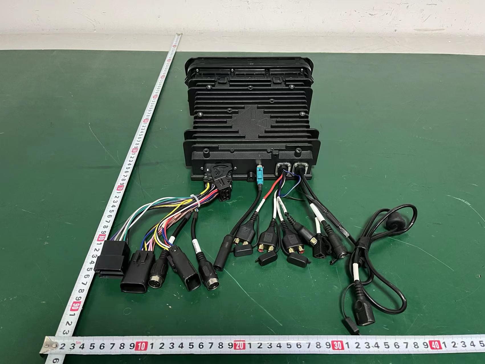
Click to zoom
Application Details
- Equipment Class
- DSS - Part 15 Spread Spectrum Transmitter
- Date of Grant
- Jan 08, 2023
- Application Purpose
- Original Equipment
- Date of Application
- Jan 08, 2023
- Equipment Note
- DIGITAL MEDIA RECEIVER
- Frequency Range
- 2402.00000000 - 2480.00000000
- Company
- Rockford Corporation
- Country
- United States
Documents & Files
Document Text
Text extracted from the exhibit documents filed with the FCC. Open a document above to read the original.
Users Manual
Installation assistance available at : DIGITAL MEDIA RECEIVER PMX-HD14 2 PRACTICE SAFE SOUND Continuous exposure to sound pressure levels over 100dB may cause permanent hearing loss. High powered auto sound systems may produce sound pressure levels well over 130dB. Use common sense and practice safe sound. 3 Design Features/Wiring Diagram HOME ButtonINFO Button POWER Button Pressing will give you access to the Home menu. Pressing this button will increase volume. Pressing this button will decrease volume. AUDIO Button Pressing will give you access to the System Settings menu to adjust the Audio function. Press & hold to view inforamtion. Press & hold for 5 seconds to Power OFF the unit, press again to Power ON the unit. SIRIUSXM INPUT USB INPUT NMEA INPUT Broadcast RF In/Out SUBWOOFER LINE OUT AUX INPUT REAR LINE OUT FRONT LINE OUT Remote Trigger (Blue/White) 4 Tap to confirm . Select the suitable Country Area list of areas. Select the suitable language used for the control screen and setting items. AREA LANGUAGE Set each item as follows Perform this setup when you use this unit first time. Initial Settings 5 check the software version of this unit. Tap to access into Sofrware information mode to INFORMATION Tap on a setting repeatedly to change setting. Tap to access the BLUETOOTH SETTINGS menu. BLUETOOTH SETTINGS Tap to restore factory default value. items. To select the language used for the control screen and setting LANGUAGE To activates or deactivates the key-touch tone. BEEP TONE To select the Dimmer mode: High/Low. DIMMER To set the 12H/24H display preference. CLOCK MODE Tap to adjust the Time / Date . TIME DATE Tap to Enable or Disable the Phone Function. allow user enable phone function after microphone plug in. When hardware no way to detect mircophone existing or not, and PHONE FUNCTION Tap / through the list to select the setting you wish to change. Tap to access the SYSTEM SETTINGS menu. Tap to access the AUDIO option from the SYSTEM SETTING menu. SYSTEM SETTINGS the difference in volume between different sources. finely adjust the volume of the current source to minimize Tap to access the Source Gain Settings to position. select the preset listening zone to fit with prefect listening Tap to access the Music Zone Settings to to 15(Rear). Fader: Adjust the Front and Rear volume balance 15(Front) to 15(Left). Balance: Adjust the left and right volume balance 15(Right) FADER BALANCE Tap to switch Subwoofer low pass filter Tap to access the Equaliser Settings. (Classical> Flast >Rock>Live>R&B>Hip Hop>Jazz>Pop>User 1>User 2). transfer function. Tap to switch Front / Rear high pass filter function. Tap to set the virtual tweeter when you are selecting front speaker. Tap to access the Cross Over Settings. Tap to adjust the delay time of the selected speaker. Tap to access the Time Alignment Settings. TIME ALIGNMENT Tap to setting you wish to adjust the frequency settings. EQUALISER Bass Boost>Source Gain) (Equaliser>Time Alignment>Cross Over>Fader.Balance>Music Zone> Tap / through the list to select the setting you wish to change. > INFORMATION) wish to change. ( AUDIO > SYSTEM SETTINGS > BLUETOOTH SETTINGS the System Setting Menu, and press / to select the setting you To access the source unit’s settings, long press the button goto AUDIO CROSSOVER Tap to adjust the sound level of the selected speaker. Tap to access the Cross Over Settings. MUSIC ZONE SOURCE GAIN FACTORY MODE 6 Apple CarPlay Press: Display the HOME screen of CarPlay Hold: To activates Siri Exits the CarPlay screen and displays Operation button on CarPlay home disconnected. terminal, the Bluetooth smartphone currently connected is When iPhone compatible with CarPlay is connected to the USB successful, please unplug and insert USB cable and try again If iPhone CarPlay connection to the Car Av System is not It is recommended to use only original cables. Connection Failed Connection Successful Connect an device via USB terminal. Connect an iPhone For details, visit http://www.apple.com/ios/carplay/ in all areas. Some features, applications, and services are not available it easier to operate iPhone. while driving. You can also use Siri voice control to make receive messages, and listen to the music from iPhone product. You can get directions, make calls, send and while driving and displays them on the screen of the car. CarPlay takes the things you want to do with iPhone CarPlay is smarter, safer way to use your iPhone in the About Apple Carplay NOTE: For details, visit http://www.apple.com/ios/carplay/ in all areas. Some features, applications, and services are not available NOTE: Apple Carplay Apple Carplay NOTE: disconnected. terminal, the Bluetooth smartphone currently connected is When iPhone compatible with CarPlay is connected to the USB successful, please unplug and insert USB cable and try again If iPhone CarPlay connection to the Car Av System is not It is recommended to use only original cables. NOTE: Application Buttons. the HOME screen 7 Radio Operations WB BAND PRESET STATION LIST settings specific to the WB TUNER. To access the WB BAND SETTINGS, this will give you access to the Indicates the state of the Radio Data System staion. RDS Tunes in only to the stations with sufficient signal strength. LOCAL SEEK This option allows you to select the difference radio tuner frequency spacing. AREA for the selected band. Automatically searches and stores the preset list with the strongest signals AUTO STORE parametrs. Tap to access the radio Setup mode. You can set radio related RADIO SETUP Tap to stores the current receiving station in memory. Tap to select you desired preset station to recalls the memorized station. see what PRESETS are saved on the unit. Tap to access the PRESETS list. Using this feature allows you to (FM>AM>WB). To operate, you can to select the tuner source you want to listen to RADIO PRESET STATION LIST stations, tap and hold / . stations, tap / on the screen. To MANUAL SEEK Tuner Operation…
Text truncated - open the document above for the full version.
Cover Letter(s)
RockfordCorporation DATE:2022.07.06 EquipmentAutorisationDivision FederalCommunicationsCommission 7435OaklandMillsRoad Columbia,MD21046 FCCID:2AA7S-PMX-HD14 ProductName:DIGITALMEDIARECEIVER RequestforConfidentiality PursuanttoSections0.457and0.459ofthecommissionsrules,weherebyrequestthat thefollowingdocumentsbeheldconfidential: (Listherethedocumentsforwhichyouareseekingconfidentiality–forexample...) Schematics Blockdiagram Operationdescription Thesematerialscontaintradesecretsandproprietaryinformationandarenot customarilyreleasedtothepublic.Thepublicdisclosureofthisinformationmightbe harmfultothecompanyandprovideunjustifiedbenefitstoourcompetitors. <Signature> Name:JonathanComune Title:VicePresidentGlobalSupplyChain Company:RockfordCorporation
Cover Letter(s)
Date:2022.11.15 FederalCommunicationsCommission Authorization&EvaluationDivision 7345OaklandMillsRoad Columbia,Maryland21046 RE:LETTEROFAGENTAUTHORIZATION ToWhomItMayConcern: We,theundersigned,herebyauthorizeComplianceTesting,LLCtoactonourbehalfinallmatters relatingtoapplicationforequipmentauthorization,includingthesigningofalldocumentsrelatingto thesematters. Wealsoherebycertifythatnopartytotheapplicationauthorizedhereunderissubjecttothedenialof benefits,includingFCCbenefits,pursuanttoSection5301oftheAnti-DrugAbuseActof1988,21 U.S.C.853(a). Sincerely, <Signature> Name:TonyTang Title:EMCEngineer Company:ESTTechnologyCo.,Ltd.
Cover Letter(s)
RockfordCorporation DATE:2022.07.06 FederalCommunicationsCommission Authorization&EvaluationDivision 7345OaklandMillsRoad Columbia,Maryland21046 AuthoritytoActasAgent Onourbehalf,Iappoint ESTTechnologyCo.,Ltd. Address: Chilingxiang, Qishantou,Santun,Houjie,Dongguan,Guangdong,China (NameofAgentcompany nameandaddress)toactasouragentinthepreparationofthisapplicationfor equipmentcertification.Icertifythatsubmitteddocumentsproperlydescribe thedeviceorsystemforwhichequipmentcertificationissought.Ialsocertify thateachunitmanufactured,importedormarketed,asdefinedintheFederal CommunicationsCommission’sregulationswillhaveaffixedtoitalabel identicaltothatsubmittedforapprovalwiththisapplication. Forinstanceswhereourauthorizedagentsignstheapplicationfor certificationonourbehalf,Iacknowledgethatallresponsibilityforcomplying withthetermsandconditionsforcertification,stillresideswithRockford CorporationAddress:600SouthRockfordDrive,Tempe,Arizona,UnitedStates (ApplicantNameandaddress) Name:JonathanComune Title:VicePresidentGlobalSupplyChain Company:RockfordCorporation
External Photos
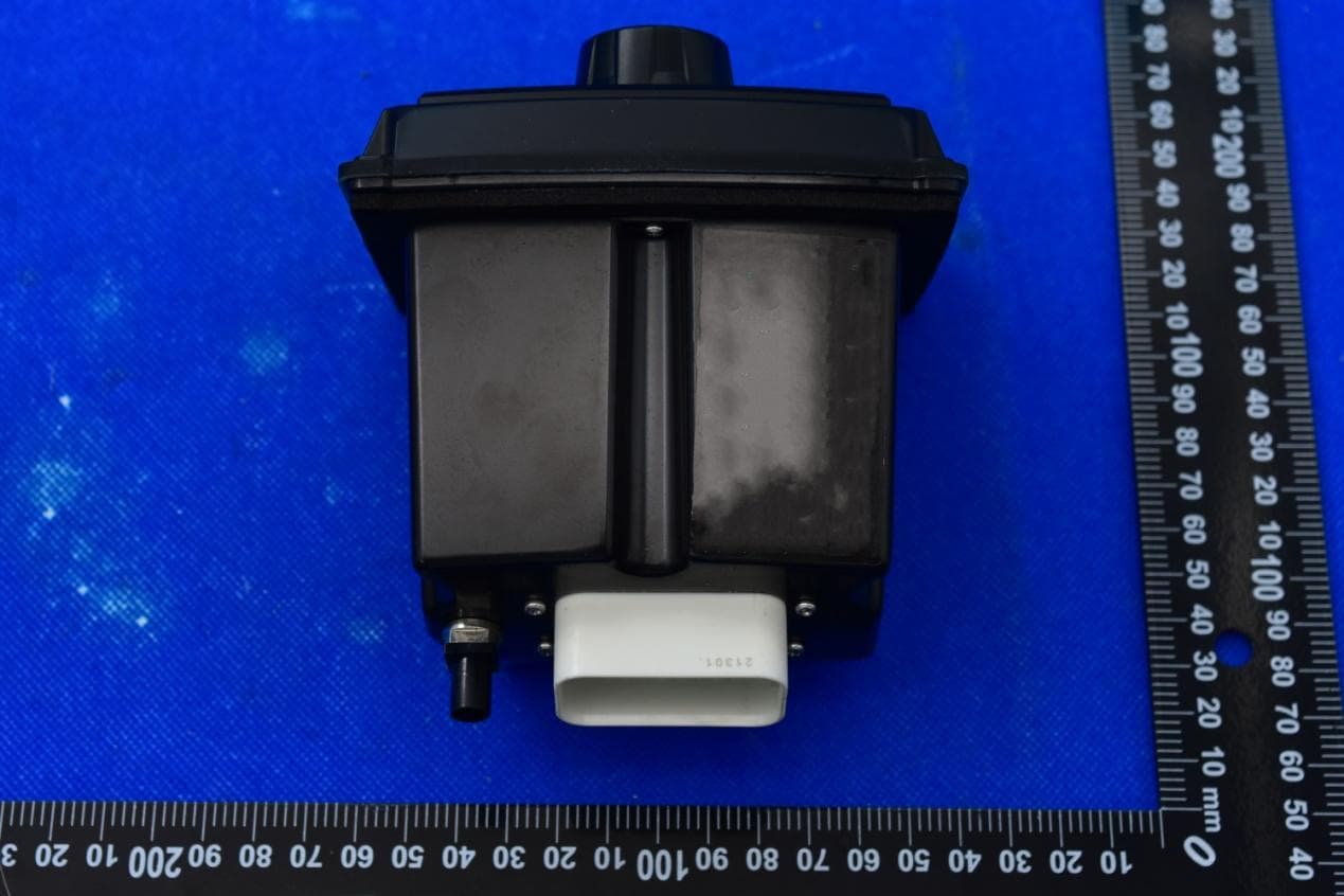
Externalphotos M/N:PMX-HD14 Externalphotos M/N:PMX-HD14 Externalphotos M/N:PMX-HD14 Externalphotos M/N:PMX-HD14 FM/AM Signalinput
Internal Photos
Internalphotos M/N:PMX-HD14 Internalphotos M/N:PMX-HD14 CW5125 Bluetooth antenna Internalphotos M/N:PMX-HD14 Internalphotos M/N:PMX-HD14 BT CW5125 Internalphotos M/N:PMX-HD14 Internalphotos M/N:PMX-HD14 Internalphotos M/N:PMX-HD14 CW889 Bluetooth antenna Internalphotos M/N:PMX-HD14
RF Exposure Info
FCCID:2AA7S-PMX-HD14 ESTTechnologyCo.,LtdReportNo.ESTE-R2207004Page1of5 FCC47CFRMPEREPORT RockfordCorporation DIGITALMEDIARECEIVER ModelNumber:PMX-HD14 FCCID:2AA7S-PMX-HD14 Applicant:RockfordCorporation Address:600SouthRockfordDrive,Tempe,Arizona,UnitedStates PreparedBy:ESTTechnologyCo.,Ltd. Chilingxiang,Qishantou,Santun,Houjie,Dongguan,Guangdong,China Tel:86-769-83081888-808 ReportNumber:ESTE-R2207004 DateofTest:Nov.25,2021~Jul.01,2022 DateofReport:Jul.04,2022 FCCID:2AA7S-PMX-HD14 ESTTechnologyCo.,LtdReportNo.ESTE-R2207004Page2of5 MaximumPermissibleExposure 1.ApplicableStandards Systemsoperatingundertheprovisionsofthissectionshallbeoperatedina mannerthatensuresthatthepublicisnotexposedtoradiofrequencyenergy levelinexcesslimitformaximumpermissibleexposure.Inaccordancewith 47CFRFCCPart2SubpartJ,section2.1091thisdevicehasbeendefinedas amobiledevicewherebyadistanceof0.2mnormallycanbemaintained betweentheuserandthedevice. 1.1.LimitsforMaximumPermissibleExposure(MPE) (a)LimitsforOccupational/ControlledExposure Frequency Range (MHz) ElectricField Strength(E) (V/m) MagneticField Strength(H) (A/m) PowerDensity(S) (mW/cm 2 ) AveragingTimes ︱E︱ 2 ,︱H︱ 2 orS (minutes) 0.3-3.06141.63(100)*6 3.0-301842/f4.89/f(900/f)*6 30-30061.40.1631.06 300-1500F/3006 1500-1000056 (b)LimitsforGeneralPopulation/UncontrolledExposure Frequency Range(MHz) ElectricField Strength(E) (V/m) MagneticField Strength(H) (A/m) PowerDensity(S) (mW/cm 2 ) AveragingTimes ︱E︱ 2 ,︱H︱ 2 orS (minutes) 0.3-1.346141.63(100)*30 1.34-30824/f2.19/f(180/f)*30 30-30027.50.0730.230 300-1500F/150030 1500-100001.o30 Note:f=frequencyinMHz;*Plane-waveequivalentpowerdensity FCCID:2AA7S-PMX-HD14 ESTTechnologyCo.,LtdReportNo.ESTE-R2207004Page3of5 1.2.MPECalculationMethod E(V/m)= d G×P×30 PowerDensity:Pd(W/m 2 )= 377 E 2 E=ElectricField(V/m) P=PeakRFoutputPower(W) G=EUTAntennanumericgain(numeric) d=Separationdistancebetweenradiatorandhumanbody(m) Theformulacanbechangedto Pd= 2 d×377 G×P×30 FromthepeakEUTRFoutputpower,theminimummobileseparationdistance,d=0.2m,as wellasthegainoftheusedantenna,theRFpowerdensitycanbeobtained FCCID:2AA7S-PMX-HD14 ESTTechnologyCo.,LtdReportNo.ESTE-R2207004Page4of5 2.ConductedPowerResult Module:CW5125 Mode Frequency (MHz) Peakoutputpower (dBm) Peakoutputpower (mW) Target power (dBm) Antennagain (dBi)(Linear) GFSK 24028.717.430 8±1 3.082.032 24418.276.714 8±1 3.082.032 24808.246.668 8±1 3.082.032 8-DPSK 240211.2213.243 11±1 3.082.032 244111.2313.274 11±1 3.082.032 248011.1212.942 11±1 3.082.032 Module:CW889 Mode Frequency (MHz) Peakoutputpower (dBm) Peakoutputpower (mW) Target power (dBm) Antennagain (dBi)(Linear) GFSK 24025.743.750 5±1 -1.50.708 24417.105.129 7±1 -1.50.708 24806.464.426 6±1 -1.50.708 8-DPSK 24021.751.496 1±1 -1.50.708 24412.271.687 2±1 -1.50.708 24802.691.858 2±1 -1.50.708 FCCID:2AA7S-PMX-HD14 ESTTechnologyCo.,LtdReportNo.ESTE-R2207004Page5of5 3.CalculatedResultandLimit Mode Target power (dBm) Antennagain Power Density (S) (mW /cm2) Limited of Power Density (S) (mW /cm2) Test Result (dBi)(Linear) Module:CW5125 GFSK93.082.0320.003211Complies 8-DPSK123.082.0320.006411Complies Module:CW889 GFSK8-1.50.7080.000891Complies 8-DPSK3-1.50.7080.000281Complies PowerDensity (S) (mW /cm2) CW5125 PowerDensity (S) (mW /cm2) CW889 PowerDensity (S) (mW /cm2) Total Ratio Limited of PowerDensity (S) (mW /cm2) Ratio Test Result 0.006410.000890.007301Complies EndofTestReport
Test Report
FCC ID: 2AA7S-PMX-HD14 EST Technology Co., Ltd Report No. ESTE-R2207001 Page 1 of 74 FCC PART 15C TEST REPORT FOR CERTIFICATION On Behalf of Rockford Corporation DIGITAL MEDIA RECEIVER Model Number: PMX-HD14 FCC ID: 2AA7S-PMX-HD14 Applicant : Rockford Corporation Address: 600 South Rockford Drive, Tempe, Arizona, United States Prepared By: EST Technology Co., Ltd. Chilingxiang, Qishantou, Santun, Houjie, Dongguan, Guangdong, China Tel: 86-769-83081888-808 Report Number: ESTE-R2207001 Date of Test: Nov. 25, 2021~Jul. 01, 2022 Date of Report: Jul. 04, 2022 FCC ID: 2AA7S-PMX-HD14 EST Technology Co., Ltd Report No. ESTE-R2207001 Page 2 of 74 TABLE OF CONTENTS Description Page TEST REPORT VERIFICATION......................................................................................................................... 3 1. GENERAL INFORMATION ................................................................................................................. 5 1.1. Description of Device (EUT) ........................................................................................................... 5 1.2. Antenna Information ........................................................................................................................ 5 1.3. Information of RF Cable .................................................................................................................. 5 2. SUMMARY OF TEST ......................................................................................................................... 6 2.1. Summary of test result ...................................................................................................................... 6 2.2. Test Facilities ................................................................................................................................... 7 2.3. Measurement uncertainty ................................................................................................................. 8 2.4. Assistant equipment used for test ..................................................................................................... 8 2.5. Block Diagram ................................................................................................................................. 8 2.6. Test mode ......................................................................................................................................... 9 2.7. Channel List ................................................................................................................................... 10 2.8. Power Setting of Test Software ...................................................................................................... 10 2.9. Test Equipment ............................................................................................................................... 11 3. MAXIMUM PEAK OUTPUT POWER ................................................................................................. 12 3.1. Limit ............................................................................................................................................... 12 3.2. Test Setup ....................................................................................................................................... 12 3.3. Spectrum Analyzer Setting ............................................................................................................. 12 3.4. Test Procedure ................................................................................................................................ 12 3.5. Test Result ...................................................................................................................................... 13 4. 20 DB BANDWIDTH ....................................................................................................................... 18 4.1. Limit ............................................................................................................................................... 18 4.2. Test Setup ....................................................................................................................................... 18 4.3. Spectrum Analyzer Setting ............................................................................................................. 18 4.4. Test Procedure ................................................................................................................................ 18 4.5. Test Result ...................................................................................................................................... 19 5. CARRIER FREQUENCY SEPARATION .............................................................................................. 24 5.1. Limit ............................................................................................................................................... 24 5.2. Test Setup ....................................................................................................................................... 24 5.3. Spectrum Analyzer Setting ............................................................................................................. 24 5.4. Test Procedure ................................................................................................................................ 24 5.5. Test Result ...................................................................................................................................... 25 6. NUMBER OF HOPPING CHANNEL .................................................................................................. 30 6.1. Limit ............................................................................................................................................... 30 6.2. Test Setup .............................................................................................................…
Text truncated - open the document above for the full version.
Test Report
FCC ID: 2AA7S-PMX-HD14 EST Technology Co., Ltd Report No. ESTE-R2207002 Page 1 of 74 FCC PART 15C TEST REPORT FOR CERTIFICATION On Behalf of Rockford Corporation DIGITAL MEDIA RECEIVER Model Number: PMX-HD14 FCC ID: 2AA7S-PMX-HD14 Applicant : Rockford Corporation Address: 600 South Rockford Drive, Tempe, Arizona, United States Prepared By: EST Technology Co., Ltd. Chilingxiang, Qishantou, Santun, Houjie, Dongguan, Guangdong, China Tel: 86-769-83081888-808 Report Number: ESTE-R2207002 Date of Test: Nov. 25, 2021~Jul. 01, 2022 Date of Report: Jul. 04, 2022 FCC ID: 2AA7S-PMX-HD14 EST Technology Co., Ltd Report No. ESTE-R2207002 Page 2 of 74 TABLE OF CONTENTS Description Page TEST REPORT VERIFICATION......................................................................................................................... 3 1. GENERAL INFORMATION ................................................................................................................. 5 1.1. Description of Device (EUT) ........................................................................................................... 5 1.2. Antenna Information ........................................................................................................................ 5 1.3. Information of RF Cable .................................................................................................................. 5 2. SUMMARY OF TEST ......................................................................................................................... 6 2.1. Summary of test result ...................................................................................................................... 6 2.2. Test Facilities ................................................................................................................................... 7 2.3. Measurement uncertainty ................................................................................................................. 8 2.4. Assistant equipment used for test ..................................................................................................... 8 2.5. Block Diagram ................................................................................................................................. 8 2.6. Test mode ......................................................................................................................................... 9 2.7. Channel List ................................................................................................................................... 10 2.8. Power Setting of Test Software ...................................................................................................... 10 2.9. Test Equipment ............................................................................................................................... 11 3. MAXIMUM PEAK OUTPUT POWER ................................................................................................. 12 3.1. Limit ............................................................................................................................................... 12 3.2. Test Setup ....................................................................................................................................... 12 3.3. Spectrum Analyzer Setting ............................................................................................................. 12 3.4. Test Procedure ................................................................................................................................ 12 3.5. Test Result ...................................................................................................................................... 13 4. 20 DB BANDWIDTH ....................................................................................................................... 18 4.1. Limit ............................................................................................................................................... 18 4.2. Test Setup ....................................................................................................................................... 18 4.3. Spectrum Analyzer Setting ............................................................................................................. 18 4.4. Test Procedure ................................................................................................................................ 18 4.5. Test Result ...................................................................................................................................... 19 5. CARRIER FREQUENCY SEPARATION .............................................................................................. 24 5.1. Limit ............................................................................................................................................... 24 5.2. Test Setup ....................................................................................................................................... 24 5.3. Spectrum Analyzer Setting ............................................................................................................. 24 5.4. Test Procedure ................................................................................................................................ 24 5.5. Test Result ...................................................................................................................................... 25 6. NUMBER OF HOPPING CHANNEL .................................................................................................. 30 6.1. Limit ............................................................................................................................................... 30 6.2. Test Setup .............................................................................................................…
Text truncated - open the document above for the full version.
Test Report
CW889 PCB Antenna Applications 2.4GHz WLAN, Home RF, Bluetooth Modules, etc. Specifications Part Number Frequency Range (MHz) Peak Gain (dBi typ.) VSWR Impedance CW889 2400~2500 -1.5 (YZ-V)2 max. 50Ω Operating Temperature Range : -40 ~ +125°C Storage Temperature Range : -40 ~ +125°C Dimensions Antenna Smith Chart 20mm 7.78 mm 11.4mm 16.6mm 2.15mm Antenna gain / Efficiency Frequency Gain (dBi)Effciency() 2400MHz 2410MHz 2420MHz 2430MHz 2440MHz 2450MHz 2460MHz 2470MHz 2480MHz 2490MHz 2500MHz -1.60 -1.50 -1.55 -1.86 -2.10 -1.86 -1.62 -2.40 -2.96 -2.74 -2.60 18% 18% 18% 16% 14% 15% 15% 13% 12% 13% 13%
Test Report
Address:802,BuildingG,GuanchengLowCarbonIndustrialPark,ShangcunCommunity, GongmingStreet,GuangmingDistrict,Shenzhen,china Doublecoppertubeantenna Modelname:SM300
Test Setup Photos
Radiatedemissiontest:Below1GHz Radiatedemissiontest:Above1GHz
Contact Information
Applicant
Jonathan Comune(Vice President Global Supply Chain)
Test Firm
EST Technology Co., Ltd.Iceman Hu
[email protected]+86 0769-83081888
Technical Specifications
| # | Rule Parts | Frequency Range | Power Output |
|---|---|---|---|
| 1 | 15C | 2.40 GHz - 2.48 GHz | 13.30 mW |
Other Applications from Rockford Corporation
2AA7SPMXP2
Jan 17, 2023DIGITAL MEDIA RECEIVER with Bluetooth
Equipment Class
DSS - Part 15 Spread Spectrum Transmitter
2AA7S-PMXP2
Nov 08, 2022DIGITAL MEDIA RECEIVER
Equipment Class
DSS - Part 15 Spread Spectrum Transmitter
2AA7S-76001074
Jan 19, 2022Bluetooth Audio Amplifier
Equipment Class
DSS - Part 15 Spread Spectrum Transmitter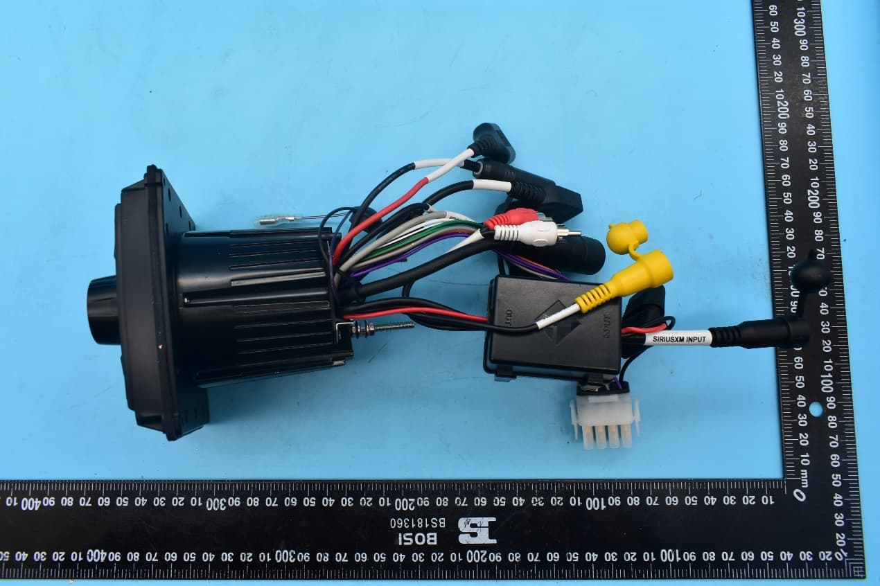
2AA7S-PMX3
May 25, 2021DIGITAL MEDIA RECEIVER with Bluetooth
Equipment Class
DSS - Part 15 Spread Spectrum Transmitter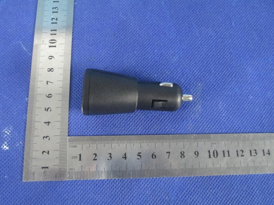
2AA7SRFBTAUX
Nov 14, 2013Bluetooth to AUX input audio adapter
Equipment Class
DSS - Part 15 Spread Spectrum Transmitter