2AA89-I2400Expendable Unattended Ground Sensor Wired Version
Applied Research Associates, Inc.
Click to zoom
Application Details
- Equipment Class
- DXT - Part 15 Low Power Transceiver, Rx Verified
- Date of Grant
- Mar 23, 2014
- Application Purpose
- Original Equipment
- Date of Application
- Nov 08, 2013
- Equipment Note
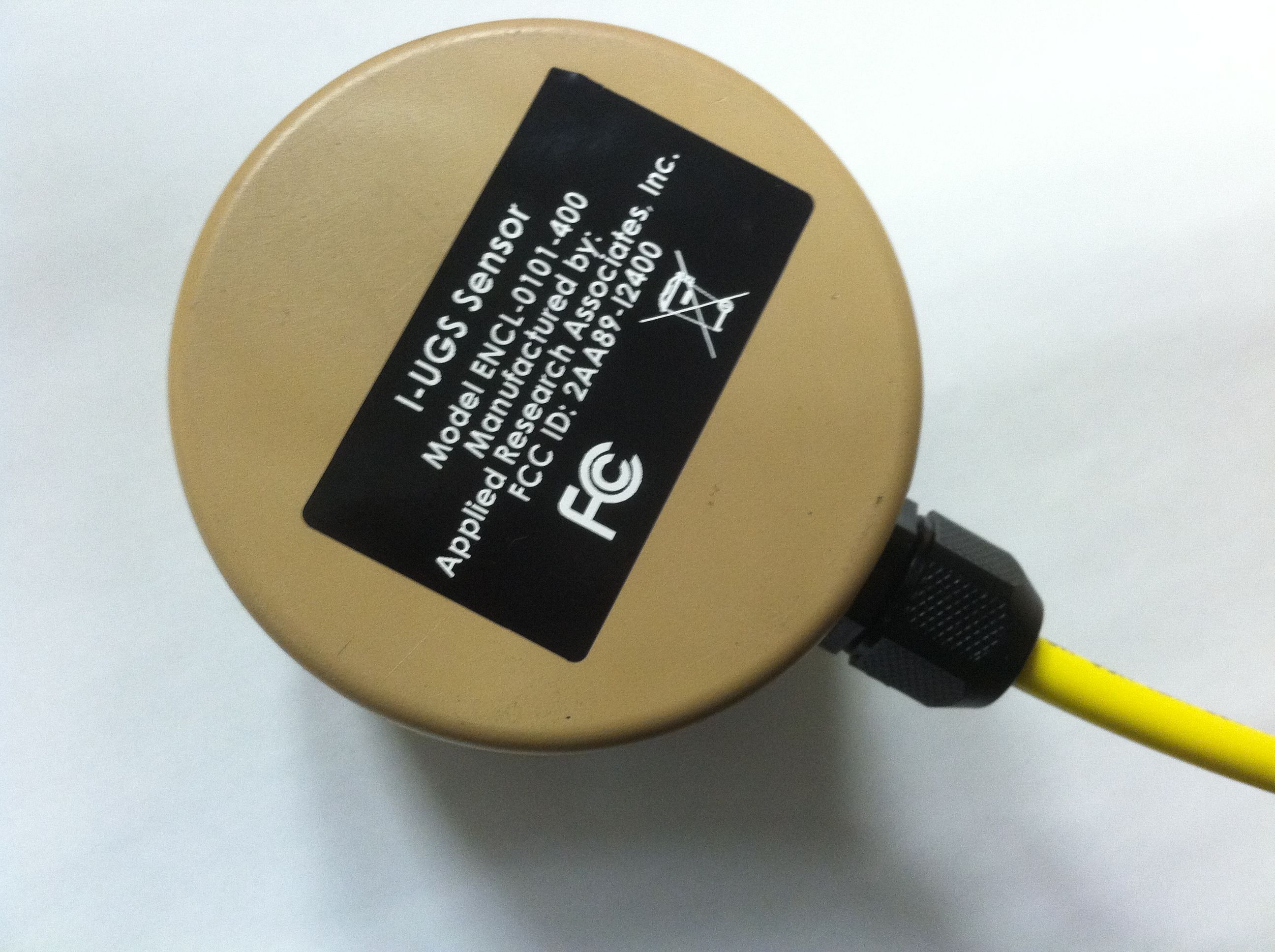
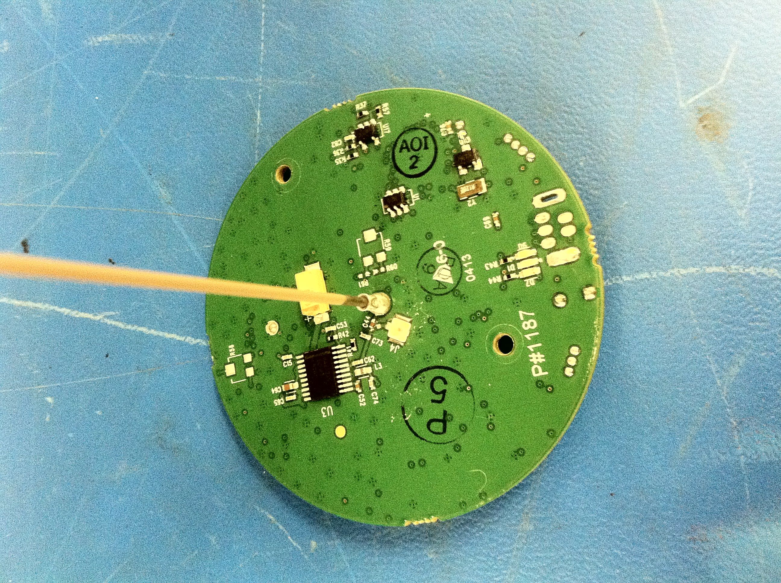
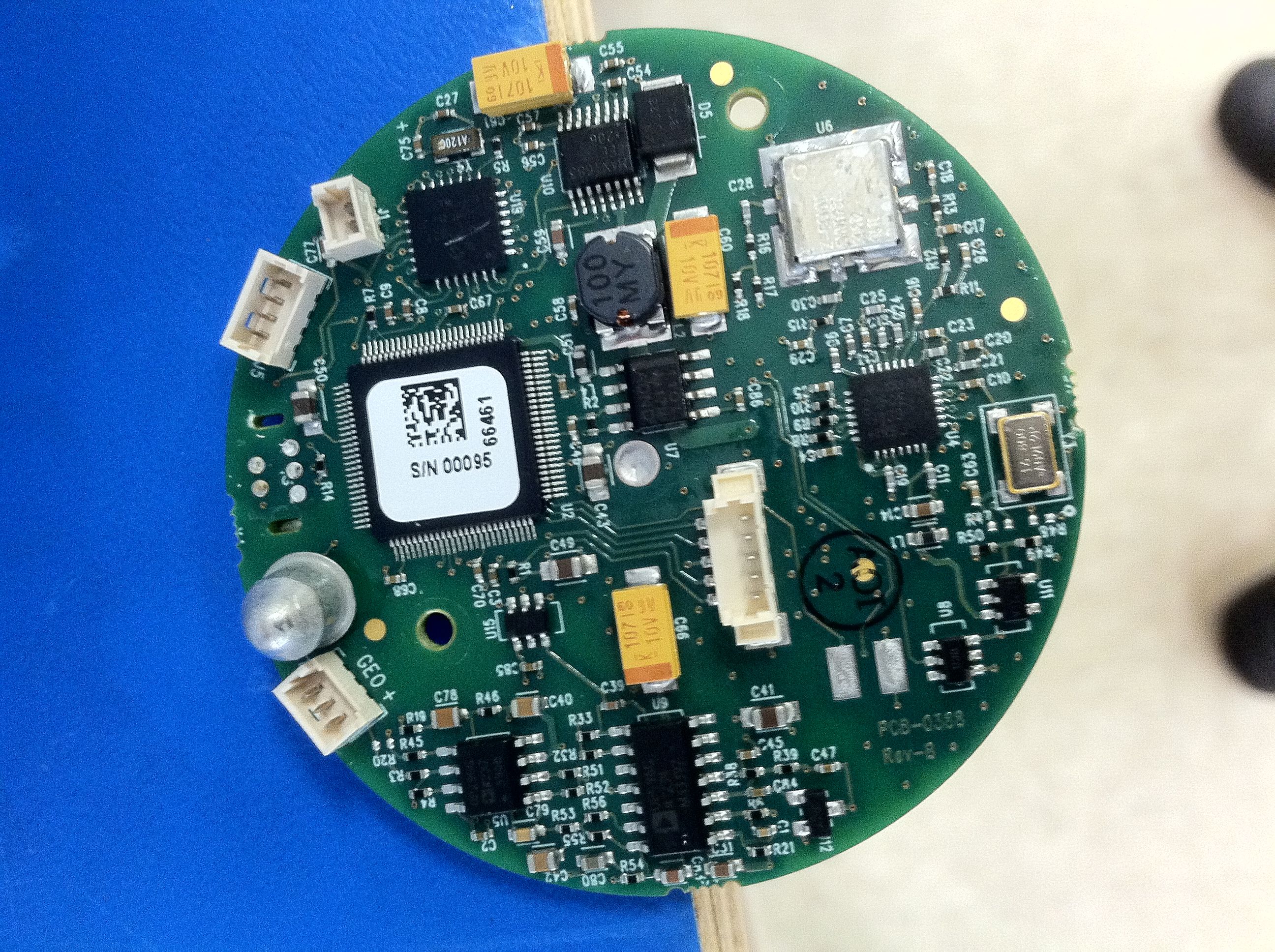
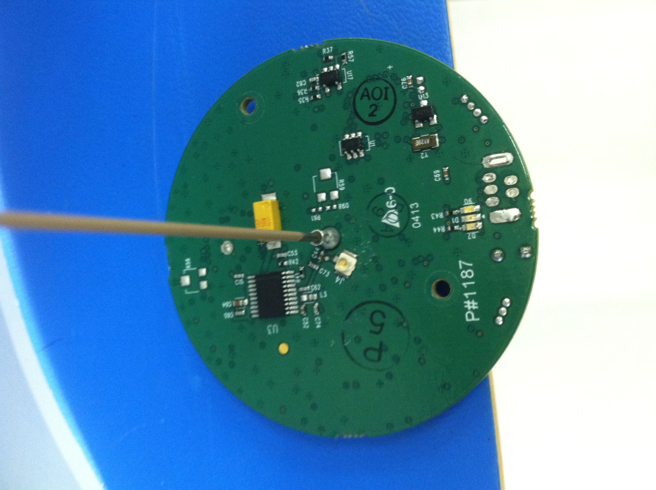
- Expendable Unattended Ground Sensor Wired Version
- Frequency Range
- 916.00000000 - 917.00000000
- Country
- United States
Documents & Files
Document Text
Text extracted from the exhibit documents filed with the FCC. Open a document above to read the original.
Users Manual
System 2000 Manual Part Number: DOC-3001 SYSTEM 2000 USER MANUAL MAINTENANCE AND OPERATION INSTRUCTIONS WITH PARTS BREAKDOWN Expendable Unattended Ground Sensor (E-UGS) System Revision A WARNING – The US Department of Commerce, Bureau of Industry and Security, has classified the E-UGS as ECCN 6A999.c (Commerce Control List, Part 774, Supplement No.1). This means the E-UGS system must not be exported or re- exported to embargoed or sanctioned countries, to parties of concern, or in support of prohibited end-uses (in the case of E-UGS, the prohibited end-use is Antiterrorism) 04 December 2013 E-UGS User Manual DOC-3001 E-UGS System 2000 i ECCN 6A999.c CONTROLLED DOCUMENT, REFER TO COVER STATEMENT (THIS PAGE INTENTIONALLY LEFT BLANK) E-UGS User Manual DOC-3001 E-UGS System 2000 ii ECCN 6A999.c CONTROLLED DOCUMENT, REFER TO COVER STATEMENT Table of Contents 1 SYSTEM SAFETY WARNINGS ..................................................... 5 2 FCC NOTICE .............................................................................. 5 3 THEORY OF OPERATIONS ......................................................... 5 4 EQUIPMENT DESCRIPTION ....................................................... 7 4.1 STORAGE AND TRANSPORT CASES .................................................... 7 4.1.1 Base Station Kit ............................................................. 8 4.1.2 Optional Sensor Kit ........................................................ 9 4.2 BASE STATION COMPONENTS ....................................................... 10 4.2.1 Receiver ....................................................................... 11 4.2.2 USB Cable .................................................................... 12 4.2.3 Receiver Antenna ........................................................ 12 4.2.4 E-UGS Software CD ..................................................... 13 4.2.5 Receiver Antenna Cable .............................................. 13 4.2.6 User Manual and Quick Reference Cards .................... 14 4.3 SENSORS AND EMPLACEMENT TOOLS ............................................. 14 4.3.1 E-UGS Sensors (Battery Powered) .............................. 15 4.3.2 E-UGS Sensors (Shore Powered) ................................. 16 4.3.3 Quick Reference Cards ................................................ 18 4.3.4 Emplacement Tools ..................................................... 18 5 BASE STATION OPERATION .................................................... 20 5.1 BASE STATION SETUP .................................................................. 20 5.1.1 Parts Check .................................................................. 20 5.1.2 Base Station Connections ............................................ 20 E-UGS User Manual DOC-3001 E-UGS System 2000 iii ECCN 6A999.c CONTROLLED DOCUMENT, REFER TO COVER STATEMENT 5.1.3 Antenna Mounting ...................................................... 20 5.2 E-UGS SOFTWARE ..................................................................... 21 5.2.1 Install E-UGS Software ................................................ 21 5.2.2 Software Features ....................................................... 21 5.2.3 Software Main Menu .................................................. 22 5.2.4 Software Operations ................................................... 30 6 SENSOR OPERATION............................................................... 41 6.1 BATTERY POWERED SENSORS ........................................................ 41 6.1.1 Sensor Buttons ............................................................ 41 6.1.2 Sensor Operational Modes .......................................... 44 6.2 SHORE POWERED (WIRED) SENSORS .............................................. 46 6.3 SENSOR TRANSPORT.................................................................... 46 6.4 SENSOR EMPLACEMENT ............................................................... 47 6.4.1 Burial Emplacement .................................................... 47 6.4.2 Surface Emplacement ................................................. 48 6.4.3 Sensor Geo-Location ................................................... 49 6.4.4 Sensor Area Coverage ..... Error! Bookmark not defined. 6.4.5 Sensor Detection Radius.............................................. 50 6.4.6 Sensor Transmission Range ......................................... 50 6.4.7 Sensor Reports ............................................................ 51 6.4.8 Battery Status (Battery Powered Only) ....................... 54 7 WORKING WITH MAPS ........................................................... 55 7.1 QUICK MAP AND GENERATE MAP ................................................. 55 7.2 MAP FAVORITES ......................................................................... 56 7.3 CREATING NEW MAPS ................................................................. 59 7.3.1 Maps from Google Earth™ .......................................... 59 7.3.2 Saving Map Images and Coordinates ......................... 62 E-UGS User Manual DOC-3001 E-UGS System 2000 iv ECCN 6A999.c CONTROLLED DOCUMENT, REFER TO COVER STATEMENT 7.3.3 Maps from other Sources ............................................ 69 7.3.4 Geo-Rectifying Images – E-UGS World File Tool ......... 70 8 TROUBLESHOOTING GUIDE .................................................... 74 8.1 SUMMARY OF ERROR DIALOGS ...................................................... 74 8.2 TROUBLESHOOTING MATRIX ......................................................... 76 9 MAINTENANCE ....................................................................... 81 9.1 COMPUTER AND SOFTWARE UPGRADE AND DIAGNOSTICS .................. 81 9.2 SENSOR BATTERY REPLACEMENT ................................................... 84 10 SAFETY SUMMARY ................................................................. 92 10.1 GENERAL SAFETY INSTRUCTIONS ......................................…
Text truncated - open the document above for the full version.
Operational Description
APPLIED RESEARCH ASSOCIATES, INC. Unmanned Systems & Security Products Division 250 Beanville Road • Randolph, VT 05060 (802) 728-4588 • Fax: (802) 728-7490 • www.ara.com E-UGS SYSTEM 2000 Operation November 11, 2013 The E-UGS System 2000 includes multiple E-UGS sensors, a base station receiver, software, cables, an antenna and assorted hardware for mounting the equipment. The E-UGS system is a near real-time situational awareness tool that is simple to deploy, operate and transport. The E- UGS sensors are small, easy to conceal and low cost. After detection, the report signal is wirelessly transmitted via ARA’s patented Extended Range Radio Frequency (ERRF) link. This unique radio link ensures that the sensor reports can be transmitted over unprecedented long ranges directly to the compact base station receiver. This eliminates the need for repeaters or mesh networks. The E-UGS system is applicable to security applications to include reporting activity along roads, paths and borders, around perimeters and in sparsely occupied areas including rugged outdoor environments.
Test Report
Serial No. GM213072f FCC ID: 2AA89-I2400 FCC TEST REPORT FOR THE APPLIED RESEARCH ASSOCIATES, INC. EXPENDABLE UNATTENDED GROUND SENSORS (E-UGS) SYSTEM FCC ID: 2AA89-I2400 Prepared for: Applied Research Associates, Inc. (NED) 250 Beanville Road Randolph, VT 05060 USA Submitted by: Green Mountain Electromagnetics, Inc. (802) 388-3390 (802) 388-6279 Fax [email protected] 219 Blake Roy Road • Middlebury, Vermont 05753 Copyright: November 8, 2013 This report shall not be reproduced, except in full, without the written approval of GME. GME Test Lab Cert 898.01 Serial No. GM213072f ARA, Inc. FCC ID: 2AA89-I2400 November 2013 Page 2 of 32 GME, Inc. • 219 Blake Roy Road • Middlebury, VT 05753 • Tel: 802-388-3390 • gmelectro.com GME Applied Research Associates, Inc. FCC Testing At Green Mountain Electromagnetics, Inc. Unit: Expendable Unattended Ground Sensors (E-UGS) System Received: 9/16/13 Tested: September 26, 2013 I. Applicable Standards: The units described in this report were measured for verification of compliance with "47 CFR, Part 15 – Radio Frequency Devices, Subpart C: Intentional Radiators," paragraphs 15.207 "Conducted Emissions", 15.209 "Radiated Emissions" and 15.249 "Operation in the Bands 902- 928 MHz, 2400-2483.5 MHz, 5725-5875 MHz and 24.0-24.25 GHz." Measurement procedures were in accordance with ANSI C63.4, "Methods of Measurement of Radio-Noise Emissions from Low-Voltage Electrical and Electronic Equipment in the Range of 9 kHz to 40 GHz (2009)," and FCC OET Bulletin 65, "Evaluating Compliance with FCC Guidelines for Human Exposure to Radiofrequency Electromagnetic Fields (Jan. 2001)." Additionally, the units described in this report were measured for certification with the Code of Federal Regulations Chapter 47 – "Telecommunication, Part 2 – Frequency Allocations and Radio Treaty Matters: General Rules and Regulations, Subpart J – Equipment Authorization Procedures." Measurements required were per paragraphs 2.1046 RF Power Output, 2.1047 Modulation Characteristics, 2.1049 Occupied Bandwidth, 2.1053 Field Strength of Spurious Radiation, 2.1055 Frequency Stability and 2.1093 Radiofrequency Radiation Exposure Evaluation: Portable Devices. II. Measurement Location: The GME laboratory and Open Area Test Site (OATS) are located at 219 Blake Roy Road, Middlebury, VT. The OATS is a 10/3/1-meter site complete with antenna positioner, ground plane and motorized turntable. The OATS is constructed in accordance with ANSI C63.7-2005 and complies with the requirements for radiated emissions testing in ANSI C63.4-2009 and CISPR standards. GME is internationally accredited by the American Association for Laboratory Accreditation (A2LA) and meets the quality requirements in ISO/IEC 17025 (2005), "General Requirements for the Competence of Testing and Calibration Laboratories." Serial No. GM213072f ARA, Inc. FCC ID: 2AA89-I2400 November 2013 Page 3 of 32 GME, Inc. • 219 Blake Roy Road • Middlebury, VT 05753 • Tel: 802-388-3390 • gmelectro.com GME III. Unit Tested: The Applied Research Associates, Inc. Expendable Unattended Ground Sensors (E-UGS) system consists of sensors and a receiver. Sensors are connected to a siren and a power supply. The receiver is connected to a laptop PC. A sensor consists of a metal enclosure with low-voltage electronics, a 916-MHz transmitter and an integral antenna. The receiver consists of a metal enclosure with low-voltage electronics, receiver circuitry, custom USB connector and a coaxial antenna connector. The table below describes the units that were subjected to measurements determining compliance with applicable EMC standards: Product Manufacturer Part Serial Number Receiver ARA ENCL-0102 ENG001 Sensor Transmitter ARA ENCL-0101-400 77027 The following table describes the system physical and electrical properties: Part Volts/Amps/Hertz H/W/D in cm Receiver USB Powered 18/12/6 Sensor Transmitters (2) EUT: 12 VDC, 1.67 A PS: 100-240 VAC, 50/60 Hz, 0.55 A 12/6/6 The following table describes the support equipment used during testing: Product Manufacturer Part Serial Number Laptop PC Dell EG520 26086624813 Antenna Laird FG9023 06021207 Power Supply Meanwell LPV-20-12 HB33728444 Siren Velleman HAA40R 1210 Power/signal cables were used for testing and are supplied by the manufacturer. The following table describes the system cables used for testing: Cable Manufacturer Description Power (DC Transmitter) ITC 22AWG/4, UL Signal (Receiver - 2) ARA p/n CBL-0013/0015, Custom USB and RF Serial No. GM213072f ARA, Inc. FCC ID: 2AA89-I2400 November 2013 Page 4 of 32 GME, Inc. • 219 Blake Roy Road • Middlebury, VT 05753 • Tel: 802-388-3390 • gmelectro.com GME IV. Summary of Results: The Applied Research Associates, Inc. Expendable Unattended Ground Sensors (E-UGS) system complies FR 47, Paragraphs 2 and 15. Section X contains the results summarized in the table below. CFR 47 Frequency Specified Measured Test Mode/Port Paragraph Range/Level Values Values 1 Output Power Transmit 2.1046(a) 15.249(a) 916 MHz 94 dBuV/m 93 dBuV/m 2 Modulation Characteristic Transmit 2.1047(d) 15.249(d) All modulation products below general limit 46 dBuV/m 45 dBuV/m 3 Occupied Bandwidth Transmit 2.1049(i) 15.249(d) OBW below general limit @ f for 0.5% power 46 dBuV 45 dBuV @ f = 480 kHz 4 Frequency Stability Transmit 2.1055 -30 ̊C to +50 ̊C 10.2 – 13.8 VDC 916.40 MHz 916.40 MHz 916.40 MHz 916.40 MHz 5 Radiated and Spurious Emissions Enclosure 15.209 15.249 2.1053 30 - 88 MHz 88 - 216 MHz 216 - 960 MHz 960 - 9160 MHz Above 915 (Spur) 40 dBuV/m 43.5 dBuV/m 46 dBuV/m 54 dBuV/m 54 dB/V/m Within All Limits at 3 Meters 6 Conducted Emissions AC Port 15.207 150 – 500 kHz 0.5 – 5 MHz 5 – 30 MHz 66-56 dBuv QP 56 dBuV QP 60 dBuV QP Within Quasi-Peak Limits 7 Exposure Evaluation Enclosure 2.1093 916 MHz 0.08 W/kg Body 1.6 W/kg 1g Vol Within All Limits Exploratory measurements indicate maximum radiation is found when the antenna polarization is aligned with the EUT antenna and when the antenna is pointed dire…
Text truncated - open the document above for the full version.
Contact Information
Applicant
Cory Krieg
Test Firm
Green Mountain Electromagnetics, IncorporatedKyle Kowalczyk
Technical Specifications
| # | Rule Parts | Frequency Range | Power Output |
|---|---|---|---|
| 1 | 15C | 916 MHz - 917 MHz | - |