2AA8H-B0213ABT sensor
Wisesec Ltd.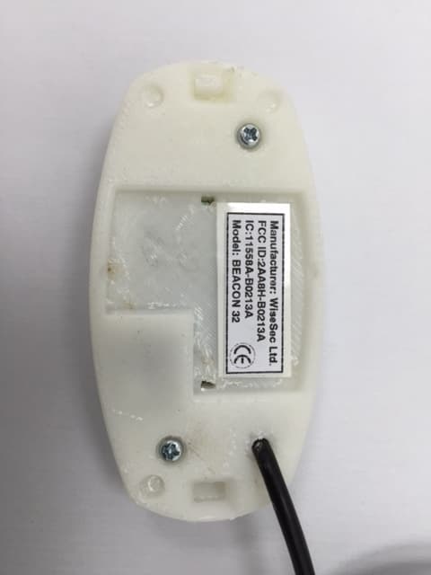
Click to zoom
Application Details
- Equipment Class
- DXX - Part 15 Low Power Communication Device Transmitter
- Date of Grant
- Jul 16, 2015
- Application Purpose
- Original Equipment
- Date of Application
- Jul 16, 2015
- Equipment Note
- BT sensor
- Frequency Range
- 2402.00000000 - 2480.00000000
- Company
- Wisesec Ltd.
- Country
- Israel
Documents & Files
Document Text
Text extracted from the exhibit documents filed with the FCC. Open a document above to read the original.
Users Manual
Beacon 32 Ceiling and wall mount BT sensor User manual MOUNTING THE SENSOR 1) Choose the position according to plan the location of the sensors. 2) Stretch the wires from the power supply into the hole for the wires. 3) Mount the sensor base on the surface with screws. 4) Connect the sensor wires to the wires from the power supply: Red ‐ "+" Black ‐ "‐". 5) Mount the sensor on the base. WIRE SIZE REQUIREMENTS Use #26 AWG or wires with a larger diameter. Use the following table to determine required wire gauge (diameter) and length of wire between the sensor and power supply. Wire Length <35m <60m <100m <150m Wire Gauge 26AWG 24AWG22AWG20AWG WIRE CONNECTIONS Run the cable through the cable entry hole and connect the wires in accordance with the following instructions: Red wire – (+5VDC) ‐ Connect to a positive Voltage output of 5VDC source (power supply) Black wire – (GND) – Connect to ground output of 5VDC source (power supply) IMPORTANT: 1) Product shall be powered from certified Limited Power Source adapter. 2) Do not install the sensor where it may encounter water, steam or oil. 3) Do not aim the sensor directly at sources of rapid heating or cooling such as : forced air ducts, heaters. TECHNICAL SPECIFICATIONS Power input : 3.4 – 5.5 VDC (PLU) Current Draw : 100mA Operating frequency : 2.4GHz Modulation: GFSK @ 2.4GHz EIRP: +3.72dBm LED indicator: Green LED is ON – Power good. Operating Temperature : ‐10ºC to +55ºC (14ºF to 131ºF) Dimensions: 70mm X 37mm X 22mm Weight : 40gr STANDARDS COMPLIANCE EN 300 440‐2 V1.4.1: 2010 EN 300 440‐1 V1.6.1: 2010 EN 301 489‐3 V1.4.1: 2002 EN 301 489‐1 V1.9.2: 2011 FCC 47 CFR Part 15 subpart C, section15.249 and RSS‐210 issue 8 Annex 2 EN 60950‐1:06 Manufacturer: WiseSec Ltd. This device complies with Part 15 of the FCC Rules. Operation is subject to the following two conditions: (1) This device may not cause harmful interference, and (2) This device must accept any interference received, including interference that may cause undesired operation. This device complies with FCC Rules Part 15 and with Industry Canada licence-exempt RSS standard(s). Operation is subject to two conditions: (1) This device may not cause harmful interference, and (2) this device must accept any interference that may be received or that may cause undesired operation. Le présent appareil est conforme aux CNR d'Industrie Canada applicables aux appareils radio exempts de licence. L'exploitation est autorisée aux deux conditions suivantes : (1) l'appareil ne doit pas produire de brouillage, et (2) l'utilisateur de l'appareil doit accepter tout brouillage radioélectrique subi, même si le brouillage est susceptible d'en compromettre le fonctionnement. NOTE: The digital circuit of this device has been tested and found to comply with the limits for a Class B digital device, pursuant to part 15 of the FCC Rules. These limits are designed to provide reasonable protection against harmful interference in a residential installation. This equipment generates, uses and can radiate radio frequency energy and, if not installed and used in accordance with the instructions, may cause harmful interference to radio communications. However, there is no guarantee that interference will not occur in a particular installation. If this equipment does cause harmful interference to radio or television reception, which can be determined by turning the equipment off and on, the user is encouraged to try to correct the interference by one or more of the following measures: -Reorient or relocate the receiving antenna. -Increase the separation between the equipment and receiver. -Connect the equipment into an outlet on a circuit different from that to which the receiver is connected. -Consult the dealer or an experienced radio/TV technician for help. Cet équipement a été testé et jugé conforme aux limites s’appliquant à un appareil numérique de classe B, conformément à la Partie 15 des réglementations de la FCC. Ces limites ont été élaborées pour offrir une protection raisonnable contre les interferences nuisibles dans une installation résidentille. Cet équipement génère, utilize et peut émettre de l’énergie de fréquence radio et, s’il n’est pas installé et utilize conformément aux instructions du fabricant, peut provoquer des interférences dangereuses pour les communications radio. Toutefois, rien ne garantit l’absence d’interférences dans une installation particuliére. Si cet équipement provoque des interférences nuisibles au niveau de la réception radio ou television, ce qui peut étre determine par la mise hors, puis sous tension de l’équipment, vous étes invite à essayer de corriger les interferences en pregnant les mesures suivantes: Réorientez ou déplaces l’antenne réceptrice. Augmentez la distance qui sépare l’équipement et le récepteur. Branchez l’équipement à une prise d’un circuit different de celui auquel est branché le récepteur. Consultez le revendeur ou un technician radio/television expérimenté pour obtenir de l’aide. Changes or modifications to this equipment not expressly approved by the party responsible for compliance (Wisesec Ltd.) could void the user’s authority to operate the equipment.
External Photos
Wisesec Ltd. FCC ID:2AA8H-B0213A IC:11558A-B0213A Page 1 of 3 EXTERNAL PHOTOGRAPHS This document contains 2 photographs Wisesec Ltd. FCC ID:2AA8H-B0213A IC:11558A-B0213A Page 2 of 3 Photograph No.1 BEACON 32 sensor front view Wisesec Ltd. FCC ID:2AA8H-B0213A IC:11558A-B0213A Page 3 of 3 Photograph No.2 BEACON 32 sensor rear side view
ID Label/Location Info
Wisesec Ltd. FCC ID:2AA8H-B0213A Page 1 of 1 Label Label location Label with FCC ID:2AA8H-B0213A is located at the rear side panel of the device. The statement according to FCC part 15 §15.19(a)(3) is placed in User’s Guide, page 4 (Application exhibit User_manual_24511).
Internal Photos
Wisesec Ltd. FCC ID:2AA8H-B0213A IC:11558A-B0213A Page 1 of 4 INTERNAL PHOTOGRAPHS This document contains 3 photographs Wisesec Ltd. FCC ID:2AA8H-B0213A IC:11558A-B0213A Page 2 of 4 Photograph No.1 BEACON 32 sensor internal view Wisesec Ltd. FCC ID:2AA8H-B0213A IC:11558A-B0213A Page 3 of 4 Photograph No.2 BEACON 32 sensor PCB second side view Wisesec Ltd. FCC ID:2AA8H-B0213A IC:11558A-B0213A Page 4 of 4 Photograph No.3 BEACON 32 sensor antenna
Test Report
Hermon Laboratories Ltd. Harakevet Industrial Zone, Binyamina 30500, Israel Tel. +972-4-6288001 Fax. +972-4-6288277 E-mail: [email protected] Page 1 of 59 Report ID: WISRAD_FCC.24511_25727.docx Date of Issue: 1-Jul-15 ELECTRICAL TESTING 0839.01 TEST REPORT ACCORDING TO: FCC 47 CFR PART 15 subpart C, section 15.249 FOR: Wisesec Ltd. BEACON32 BT sensor Model: B0213A FCC ID:2AA8H-B0213A This report is in conformity with ISO/ IEC 17025. The "A2LA Accredited" symbol endorsement applies only to the tests and calibrations that are listed in the scope of Hermon Laboratories accreditation. The test results relate only to the items tested. This test report shall not be reproduced in any form except in full with the written approval of Hermon Laboratories Ltd. Report ID: WISRAD_FCC.24511_25727.docx Date of Issue: 1-Jul-15 Page 2 of 59 Table of contents 1 Applicant information ..................................................................................................................................................... 3 2 Equipment under test attributes .................................................................................................................................... 3 3 Manufacturer information .............................................................................................................................................. 3 4 Test details .................................................................................................................................................................... 3 5 Tests summary .............................................................................................................................................................. 4 6 EUT description ............................................................................................................................................................. 5 6.1 General information ....................................................................................................................................................... 5 6.2 Ports and lines .............................................................................................................................................................. 5 6.3 Auxiliary equipment ....................................................................................................................................................... 5 6.4 Changes made in EUT .................................................................................................................................................. 5 6.5 Test configuration .......................................................................................................................................................... 5 6.6 Transmitter characteristics ............................................................................................................................................ 6 7 Transmitter tests according to 47CFR part 15 subpart C and RSS-210 requirements ................................................. 7 7.1 Field strength of emissions ............................................................................................................................................ 7 7.2 Band edge emission .................................................................................................................................................... 28 7.3 Antenna requirements ................................................................................................................................................. 32 7.4 Occupied bandwidth test ............................................................................................................................................. 33 7.5 Conducted emissions .................................................................................................................................................. 41 8 APPENDIX A Test equipment and ancillaries used for tests ....................................................................................... 45 9 APPENDIX B Measurement uncertainties ................................................................................................................... 46 10 APPENDIX C Test laboratory description ................................................................................................................... 47 11 APPENDIX D Specification references ....................................................................................................................... 47 12 APPENDIX E Test equipment correction factors ......................................................................................................... 48 13 APPENDIX F Abbreviations and acronyms ................................................................................................................. 59 Report ID: WISRAD_FCC.24511_25727.docx Date of Issue: 1-Jul-15 Page 3 of 59 1 Applicant information Client name: Wisesec Ltd. Address: 145A Yafo street, Colbo Building 9th Floor, Haifa 3525114, Israel Telephone: +972 4850 0340 E-mail: [email protected] Contact name: Mr. Vadim Maor 2 Equipment under test attributes Product name: BEACON32 BT sensor Product type: Transmitter operating at 2.4 GHz Model(s): B0213A Serial number: Prototype Hardware version: Rev.4 Software release: Rev.1 Receipt date 14-May-14 3 Manufacturer information Manufacturer name: Wisesec Ltd. Address: 145A Yafo street, Colbo Building 9th Floor, Haifa 3525114, Israel Telephone: +972 4850 0340 E-Mail: [email protected] Contact name: Mr. Vadim Maor 4 Test details Project ID: 25727 Location: Hermon Laboratories Ltd. Harakevet Industrial Zone, Binyamina 30500, Israel Test started: 6/18/2013 Test completed: 6/26/2013, 5/22/2014 Test specification(s): FCC 47 CFR Part 15, subpart C, §15.249 Report ID: WISRAD_FCC.24511_25727.docx Date of Issue: 1-Jul-15 Page 4 of 59 5 Tests summary Test Status Tran…
Text truncated - open the document above for the full version.
Test Setup Photos
Wisesec Ltd. FCC ID:2AA8H-B0213A IC:11558A-B0213A Page 1 of 6 SETUP PHOTOGRAPHS This document contains 5 photographs Wisesec Ltd. FCC ID:2AA8H-B0213A IC:11558A-B0213A Page 2 of 6 Photograph No.1 Setup for spurious emission field strength measurements in the anechoic chamber below 30 MHz Wisesec Ltd. FCC ID:2AA8H-B0213A IC:11558A-B0213A Page 3 of 6 Photograph No.2 Setup for carrier field strength, spurious emission field strength measurements in the anechoic chamber in 30 – 1000 MHz range Wisesec Ltd. FCC ID:2AA8H-B0213A IC:11558A-B0213A Page 4 of 6 Photograph No.3 Setup for spurious emission field strength measurements in the anechoic chamber in 1-18 GHz range Wisesec Ltd. FCC ID:2AA8H-B0213A IC:11558A-B0213A Page 5 of 6 Photograph No.4 Setup for spurious emission field strength measurements at the OATS above in 18-25 GHz range Wisesec Ltd. FCC ID:2AA8H-B0213A IC:11558A-B0213A Page 6 of 6 Photograph No.5 Setup for OBW measurements
Contact Information
Applicant
Tal Raveh(Chief information officer)
Technical Contact
Hermon Laboratories Ltd.Michael Nikishin
[email protected]97246268440
Harakevet Industrial zone, P.O.Box 23 · Israel
Non-Technical Contact
Wisesec Ltd.Tal Raveh
[email protected]97248500340
Test Firm
Hermon Laboratories Ltd.Alexander Usoskin
Technical Specifications
| # | Rule Parts | Frequency Range | Power Output |
|---|---|---|---|
| 1 | 15C | 2.40 GHz - 2.48 GHz | - |