2AA9NAR5Wireless Audio Amplifier with 5 speaker outputs
Levven Electronics Ltd.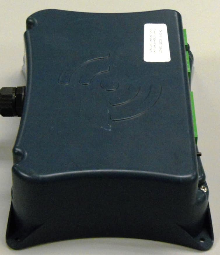
Click to zoom
Application Details
- Equipment Class
- DXT - Part 15 Low Power Transceiver, Rx Verified
- Date of Grant
- Apr 01, 2014
- Application Purpose
- Original Equipment
- Date of Application
- Apr 01, 2014
- Equipment Note
- Wireless Audio Amplifier with 5 speaker outputs
- Frequency Range
- 2400.00000000 - 2483.50000000
- Company
- Levven Electronics Ltd.
- Country
- Canada
Documents & Files
Document Text
Text extracted from the exhibit documents filed with the FCC. Open a document above to read the original.
Users Manual
AR5 AUDIO RECEIVER GoRave Receiver & Amplifier Owner’s Manual Installation and Operation Version 1.2 / 12-12-2013 TM GORAVE AR AUDIO RECEIVER & AMPLIFIER Owner’s Installation and Operation Manual V1.2 / 12-12-2013 TM 1. Getting Started 1.1 Thank You Thank you for the purchase of your GoRave AR5 audio receiver & amplifier. The GoRave AR distributes audio from mobile and wired devices to loudspeakers installed in your space. Use it with GoRave Audio Senders to cast audio into your space and swap between your devices and content sources. This manual provides basic installation and operating instructions. The manual will help you experience the performance your system was designed to produce. 1.2 Safety Precautions FOR YOUR SAFETY: ►Carefully read this manual before connecting or operating your GoRave AR receiver/amplifier. Keep this manual for later reference. ►Allow for ventilation around your GoRave AR module for heat dissipation. Keep the GoRave AR away from appliances that produce heat. ►Connect the GoRave AR to the power outlet with the supplied power supply cable. Follow all local elec- trical codes for power connection. ►Stop using the GoRave AR and have it inspected and/or serviced by qualified service personnel if: ●The power supply cord or plug has been damaged. ●Objects have fallen into or liquid has been spilled into the unit. ●The unit has been dropped or damaged in any way. 1.3 Where to Install Speaker outputs Serial port Main Power: 90 - 270VAC White: Neutral Black: Line 1 meter molded NEMA-15 power plug Auxiliary audio input (wired) Pairing button LED indicator TOP Fig 1: top view of a GoRave AR receiver/amplifier. GORAVE AR AUDIO RECEIVER & AMPLIFIER Owner’s Installation and Operation Manual V1.2 / 12-12-2013 TM The wireless GoRave Audio Senders offer a trans- mitting range of 40 feet for the USB style and 30 feet for all other styles. Install your GoRave AR5 receiver amplifier inside this transmitting radius. Include the distance needed to transmit from out- side spaces when deciding on the best location for your AR5 receiver amplifier. Mount your GoRave AR receiver/amplifier with adequate space around the unit for all audio and power connections as well as easy access the receive/pair button and LED status indicator. Use four screws (and anchors) to secure the unit to the surface. 2. Power and Control 2.1 AC Power Connection The GoRave AR receiver/amplifier should be plugged directly into a grounded power receptacle rated to deliver the power required by the GoRave AR unit and the components connected to it. Connect the power cord to the AC outlet. If local electrical codes require a hard wire connection instead of the AC power plug and socket connection, consult a qualified electrician for installation assistance. The GoRave AR receiver/amplifier will operate with a line voltage of 90-270 VAC with a line frequency of either 50Hz or 60Hz. There is no need to convert or adjust the unit in any way. NOTE: If you are going to be away from home for an extended period of time such as a month-long vacation, it is a sensible precaution to unplug your amplifier (as well as other audio and video components) while you are away. 2.2 Power Indicator The LED indicator beside the send/receive pairing button will pulse when the power cord is plugged in to an AC outlet, indicating that the amplifier is turned on. The GoRave AR5 has a built in low power sleep mode where the power supply and amplifiers will turn off when audio is not playing. Fig 2: typical installation in central closet or pantry to maximize useful 35’ transmitter range (range indicated by dashed circle). In this exam- ple, the owners have opted for stereo loudspeakers to be installed in their kitchen, master bedroom and one outdoor speaker for the patio. MASTER BEDROOM DINING ROOM LIVING ROOM GARAGE BEDROOM Centrally installed GoRave SE GORAVE AR AUDIO RECEIVER & AMPLIFIER Owner’s Installation and Operation Manual V1.2 / 12-12-2013 TM 2.3 Protection Circuitry The GoRave AR features a thermal protection circuit that protects the amplifier against potential damage in the event of extreme or faulty operating conditions. The GoRave AR’s protection circuit is independent of the audio signal and has no impact on sonic performance. The protection circuit monitors the temperature of the output devices and shuts down the amplifier if temperatures exceed safe limits. It is unlikely you will ever see this protection circuitry in action. However, should a faulty condition arise, the amplifier will stop playing and the LED indicator on the AR5 unit will flash quickly. The amplifier will automatically resume normal operation when a fault condition is removed. In most cases, the protection activates because of a fault condition such as shorted speaker wires or inad- equate ventilation leading to an overheating condition. In very rare cases, highly re active or extremely low impedance speaker loads could cause the protection circuit to engage. If the protection circuitry triggers repeatedly and you are unable to isolate and correct the faulty condition, con- tact your GoRave reseller for assistance in troubleshooting. 2.4 CAT6 Control Connection Along with installing speaker wires, GoRave recommends running a CAT6 cable from your internet / telco / electrical closet to the GoRave AR installation location. The CAT6 cable will serve for future GoRave internet remote control, home automation and television options. 3. Inputs and Outputs The GoRave AR has one wireless and one wired input connection. The wireless connect enables input from one or more wireless GoRave Audio Senders. The auxiliary wired input enables you to play analog audio from conventional audio sources such as a CD player. 3.1 Wired Input Connection Your GoRave AR5 Amplifier / Receiver has provision for 1 auxiliary connection from an external audio device. You can connect your home stereo, cd player, Airport Express, Blackberry Gateway, Xbox etc. Connect the Auxiliary Audio…
Text truncated - open the document above for the full version.
Cover Letter(s)
Levven Electronics Ltd. 9741 54 Ave NW Edmonton, AB T6E 5J4 Canada Phone: (780) 391-3000 Fax: (780) 391-3001 Confidential Letter Dec 12, 2013 Federal Communications Commission Authorization and Evaluation Division Confidentiality Request FCC ID: 2AA9NAR5 Pursuant to Sections 0.457 and 0.459 of the Commission’s Rules, the Applicant Hereby requests confidential treatment of information accompanying this application as outlined below: 1. Block Diagram 2. Circuit Diagram 3. Operational Description The above materials contain trade secrets and proprietary information not customarily released to the public. The public disclosure of these matters might be harmful to the Applicant and provide unjustified benefits to its competitors. The Applicant understands that pursuant to Rule 0.457, disclosure of this Application and all accompanying documentation will not be made before the date of the Grant for this application. Sincerely, Applicant’s company name: Levven Electronics Ltd. Applicant’s company address: 9741 54 Ave NW Edmonton, AB T6E 5J4 Canada Signed: Dec 12, 2013 Jim Qualie, Owner [email protected] (780) 391-3000
Cover Letter(s)
11/15/2013 Federal Communications Commission 445 12 th Street SW Washington, DC 20554 Subject: Limited Agency Agreement We, Levven Electronics Ltd., hereby authorized Intertek Testing Services to act as our agent for the purpose of preparing application for FCC ID number 2AA9NAR5 under all applicable parts of the FCC rules and regulations. The effective date of this limited agency agreement is 10/28/2013. The limited agency agreement expires on (insert date) unless sooner terminated or extended by written notice to Intertek Testing Services and the Federal Communications Commission. This is to advise that we are in full compliance with the Anti-Drug Abuse Act. The applicant is not subject to a denial of federal benefits pursuant to Section 5301 of the Anti-Drug Act of 1988, 21 U.S.C. 862, and no party to the application is subject to a denial of federal benefits pursuant to that section. If you have any questions or comments, please do not hesitate to contact me. Sincerely, Jim Qualie Engineering Manager and Owner Levven Electronics Ltd. (780) 391-3000
ID Label/Location Info
FFC label location on GoRave AR5
ID Label/Location Info
Proudly manufactured in A product by AR5 AUDIO RECEIVER 240VAC, 2.5 amps, 50/60 Hz single phase Certified to CAN/CSA Standard C22.2 #50065 Conforms to UL 50065 Attention: pour un usage intérieur Attention: lire le mode d’emploi Advertissment: couper le courant avant l’entretien Caution: for indoor use only Caution: read the instruction manual Warning: disconnect the electrical power before servicing FCC ID: 2AA9NAR5 IC: 11506A-AR5 MODEL: AR5 This device complies with part 15 of the FCC Rules. Operation is subject to the following two conditions: (1) This device may not cause harmful interference, and (2) this device must accept any interference received, including interference that may cause undesired operation. Serial Number:Date Manufactured:
Test Report
EMC Report for Levven Electronics. on the Model: AR5 Page 1 of 72 TEST REPORT Report Number: 101200098DEN-001F Project Number: G101200098 Report Issue Date: 01/13/2014 Product Designation: Model: AR5 Standards: FCC 47 CFR Part 15 Subpart C, 15.247 RSS-210 issue 8 2010 RSS-GEN issue 3 2010 Tested by: Client: Intertek Testing Services NA, Inc. 1795 Dogwood St. Suite 200 Louisville, CO 80027 Levven Electronics Ltd. 9741 54th Ave Edmonton, AB T6E 5J4 Report prepared by Report reviewed by Randy Thompson Senior EMC Project Engineer Michael Spataro Engineering Team Leader This report is for the exclusive use of Intertek's Client and is provided pursuant to the agreement between Intertek and its Client. Intertek's responsibility and liability are limited to the terms and conditions of the agreement. Intertek assumes no liability to any party, other than to the Client in accordance with the agreement, for any loss, expense or damage occasioned by the use of this report. Only the Client is authorized to permit copying or distribution of this report and then only in its entirety. Any use of the Intertek name or one of its marks for the sale or advertisement of the tested material, product or service must first be approved in writing by Intertek. The observations and test results in this report are relevant only to the sample tested. This report by itself does not imply that the material, product, or service is or has ever been under an Intertek certification program. Intertek Report Number: 101262612DEN-001F Issued:01/13/2014 EMC Report for Levven Electronics. on the Model: AR5 Page 2 of 72 TABLE OF CONTENTS 1 Introduction and Conclusion .............................................................................................................. 3 2 Test Summary ...................................................................................................................................... 4 3 Description of Equipment Under Test................................................................................................ 6 4 System setup including cable interconnection details, support equipment and simplified block diagram ........................................................................................................................................................ 9 5 AC Supply Variation........................................................................................................................... 12 6 Maximum Peak Output Power - Conducted..................................................................................... 13 7 -20dB Bandwidth of the Hopping Channel ...................................................................................... 19 8 Hopping Channel Carrier Frequency Separation............................................................................ 24 9 Number of Hopping Channels .......................................................................................................... 27 10 Average Time of Occupancy of the Hopping Channel - DCCF .................................................. 29 11 Spurious and Band Edge Emissions - Conducted...................................................................... 34 12 Spurious and Band Edge/Restricted Band Emissions - Radiated............................................. 41 13 Antenna Requirement .................................................................................................................... 60 14 AC Mains Conducted Emissions – Transmitter........................................................................... 61 15 RF Exposure Requirements .......................................................................................................... 69 16 Measurement Uncertainty.............................................................................................................. 71 17 Revision History ............................................................................................................................. 72 Intertek Report Number: 101262612DEN-001F Issued:01/13/2014 EMC Report for Levven Electronics. on the Model: AR5 Page 3 of 72 1 Introduction and Conclusion The tests indicated in section 2.0 were performed on the product constructed as described in section 3.0. The remaining test sections are the verbatim text from the actual data sheets used during the investigation. These test sections include the test name, the specified test Method, a list of the actual Test Equipment Used, documentation Photos, Results and raw Data. No additions, deviations, or exclusions have been made from the standard(s) unless specifically noted. Based on the results of our investigation, we have concluded the product tested complies with the requirements of the standard(s) indicated. The results obtained in this test report pertain only to the item(s) tested. General Test Methodology All measurements were performed according to the procedures in the following documents: ANSI C63.10:2009 – ANSI Standard for Testing Unlicensed Wireless Devices Test Facility Intertek Denver’s testing facilities are located at 1795 Dogwood St. Suite 200 Louisville, CO 80027. The testing facility is ISO17025:2005 accredited by A2LA, our lab code is 2506.02, our VCCI registration numbers are. R-1643, C-1752 and T-1558, our FCC designation no. US1121 and our IC lab no. 2042N. Testing contained in this test report may not be covered under the laboratories scope of accreditation. A note will be placed in the specific test section for testing not coved under the laboratories scope. Intertek Report Number: 101262612DEN-001F Issued:01/13/2014 EMC Report for Levven Electronics. on the Model: AR5 Page 4 of 72 2 Test Summary Section Test Specification Test Description Test Date Result 515.31(e)AC Supply Variation 10/11/2013 Pass 6 15.247(b)(1)/RSS-210 A8.4(2) Maximum Peak Output Power - Conducted 05/29/2013 Pass 7 15.247(a)(1)/RSS-210 A8.1(a) -20dB Bandwidth of the Hopping Channel 05/29/2013 09…
Text truncated - open the document above for the full version.
Test Setup Photos
Setup Photographs: Conducted Port Setup Photographs: Setup Photographs: AC Mains Conducted Emissions – Transmitter
Contact Information
Applicant
Jim Qualie(Engineering Manager)
Technical Contact
Non-Technical Contact
Levven Electronics Ltd.Jim Qualie
[email protected]780 391-3000
Test Firm
Intertek Testing Services NA Inc.Michael Spataro
Technical Specifications
| # | Rule Parts | Frequency Range | Power Output |
|---|---|---|---|
| 1 | 15C | 2.40 GHz - 2.48 GHz | 34.00 mW |