Text extracted from the exhibit documents filed with the FCC. Open a document above to read the original.
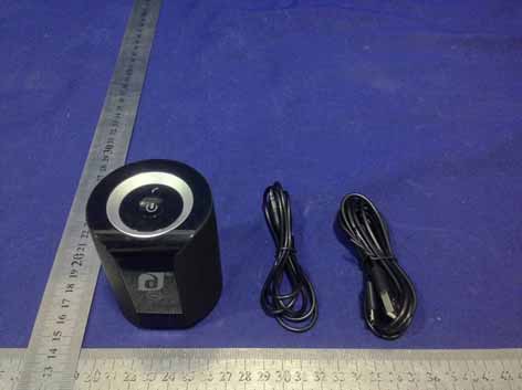
U ser Guide.indd 1 08/09/2013 22:16 Line In Line In Line In Line Out Line Out Line Out Instalação inicial este processo necessita de ser realizado apenas uma vez por cada aparelho áudio. Selecione a coluna de som L (esquerda) e ligue premindo o botão power (para ligar) durante 5 segundos. Uma vez ligada, a Reproduzir A partir do Jet, pode voltar a ligar e reproduzir/ fazer pausa do áudio. para isso, basta carregar brevemente no Configuración inicial este procedimiento debe realizarse una sola vez para cada dispositivo de audio. Seleccione el altavoz izquierdo (L) y presione el botón de encendido durante 5 segundos para encenderlo. La unidad Jet Reproducción La unidad Jet puede reconectarse a la señal de audio y reproducirla o detenerla pulsando rápidamente el botón “call”. Initial Set up this process is only required once per audio device. Select the L speaker, power on by holding down the power button for 5 seconds. Once Jet has powered up it will briefly beep while t he d logo blinks. Now press and Playback Jet can reconnect and play/pause your audio by quickly tapping the call button. coluna Jet produzirá um sinal acústico breve e o logotipo botão call (chamada). emitirá un breve pitido y el logotipo d destellará al encenderse. hold the call button for 3 seconds until a further 2 beeps d aparece intermitente. prima o botão call (chamada) durante 3 segundos até ouvir 2 sinais acústicos. As colunas Mantenga presionado el botón de llamada (“call”) durante 3 segundos hasta que escuche 2 pitidos adicionales. La unidad Jet Entrada de línea Su unidad are heard. Jet is now in pairing mode. Go to the Bluetooth settings of your audio device and search. Jet will be listed as Jet encontram-se agora em modo de emparelhamento. Agora, procure-as no ecrã de configurações Bluetooth do seu aparelho áudio. As colunas Jet aparecem como “Jet by damson”. Carregue em seleccionar ou emparelhar. Após alguns segundos o seu dispositivo será emparelhado e o logotipo d aparece a azul. Agora desligue o Jet e aguarde 10 segundos. Linha de entrada As colunas Jet dispõem de uma linha de entrada. Utilizando o cabo fornecido para o efeito, ligue o seu aparelho áudio às colunas Jet, as quais mudam automaticamente do modo Bluetooth para a linha de entrada. Neste modo (Bluetooth), o som estéreo sem fios fica desactivado. estará ahora en el modo de emparejado. Vaya a la configuración de Bluetooth de su dispositivo de audio y haga una búsqueda. La unidad Jet aparecerá como “Jet by damson”. elija seleccionar o emparejar. el dispositivo se emparejará después de unos segundos y el logotipo d permanecerá encendido. Apague la unidad Jet durante 10 segundos. Jet tiene una entrada de línea. Use el cable incluido para conectar su dispositivo de audio a la unidad Jet. La unidad cambiará automáticamente del modo Bluetooth a la entrada de línea. La señal estereofónica inalámbrica se inhabilita en este modo. “Jet by damson.” hit select or pair. After a few seconds your device will be paired, and the d logo will turn solid blue. You now need to turn Jet off and leave it for 10 seconds Using your Jet turn both Jets on, they will both beep to announce that they are twinned. the left speaker should Line in Your Jet comes with a line in. Using the cable supplied, connect your audio device to the Jet. Jet will automatically switch from Bluetooth mode to Line in. Wireless stereo will be disabled in this mode. Como utilizar o Jet Ligue ambas as colunas de som. Ambas emitem um sinal acústico o qual indicada que estão Cómo usar su unidad Jet encienda los dos altavoces Salida de línea SSi desea have reconnected to your audio device and you are now all set to stream audio and listen on one of the finest wireless Line out Should you wish to geminadas. A coluna esquerda deve ter-se ligado ao seu aparelho áudio e agora pode receber a transmissão e escutar o seu áudio numa das mais avançadas colunas de som sem fios. O som estéreo sem fios encontra-se apenas disponível no modo Bluetooth. Linha de saída Caso deseje ligar as duas colunas Jet entre si, ou ligar mais aparelhos, utilize a linha de saída de uma coluna Jet para ligar à linha de entrada de outra. Jet, ambos emitirán un pitido para indicar que están acoplados. Cuando el altavoz izquierdo se conecte nuevamente al dispositivo de audio, usted podrá transmitir y escuchar audio en uno de los mejores altavoces inalámbricos jamás producidos. La señal estereofónica inalámbrica se obtiene solamente en el modo Bluetooth. conectar entre sí los altavoces o más unidades Jet, conecte la salida de línea de una unidad Jet a la entrada de línea de otra. speakers ever produced. Wireless stereo is only available in Bluetooth mode. connect your Jets together, or indeed connect more sets, use the line out of one Jet to the line in of another. m parelhamento NFC O equipamento Jet permite o p arelhamento NFC (Near Field Communications, comunicação c ampo próximo). O NFC permite o emparelhamento imediato. a realizar o emparelhamento por NFC, certifique-se primeiro esta funcionalidade esteja ligada no seu aparelho. de u ida, toque no aparelho abaixo do logotipo d na parte n teira do Jet. por vezes, o emparelhamento pode não ser d iato. Se isto acontecer, prima o botão call (chamada) durante g undos até ouvir 2 sinais acústicos e coloque o seu aparelho m o NFC ligado abaixo do logotipo “d”. r antia Caso as suas colunas de som Jet e sentem nos primeiros 12 meses de garantia quer funcionamento defeituoso, a damson e ce-lhe um serviço de reparação ou de substituição. sulte o site www.damsonaudio.com para mais r mações sobre a nossa garantia de produto. C As alterações ou modificações que não tenham sido r essamente aprovadas pela entidade responsável podem l ar o direito de utilização por parte do utilizador. RVAÇÃO: este dispositivo foi testado e considerado em conformidade com o e lecido para os dispositivos digitais da Classe B, de acordo com a Secção 15 das a s FCC. estes limites são projectados para garantir a protecç…
Text truncated - open the document above for the full version.
SCS-F18: Project and Product Certification Representative Authorization Letter Page 1 of 2 Rev 5.0 775 Montague Expressway Milpitas, CA 95035 Tel: 408-526-1188 Fax: 408-526-1088 Email: [email protected] Project and Product Certification Representative Authorization Letter Reason for Amendment (current / obsolete) Revision History Approved Date From To Initial Release (obsolete) 1.0 1.0 Nov-14-2006 Revised wording (obsolete) 1.0 2.0 Sept–25-2007 Updated company template (obsolete) 2.0 3.0 Jan-31-2012 Updated letter information (obsolete) 3.0 4.0 May-23-2014 Added FCC ID field (current) 4.0 5.0 Sept 16 2014 SCS-F18: Project and Product Certification Representative Authorization Letter Page 2 of 2 Rev 5.0 Damson Limited 2014-09-30 To: SIEMIC, INC. 775 Montague Expressway, Milpitas, CA 95035 USA Dear Sir/Madam, Re: Product Certification Representative Authorization Letter We, _Damson Limited _hereby authorize SIEMIC, Inc. to act as a Certification Body for certifying for the following project(s): Vibration Speaker, DAIDT05 FCC ID: 2AA9Y-DAIDT05 Sincerely, signature James Talbot/General manager E-mail: [email protected] Phone: 44(0)1423 330805 Fax: 44(0)1423 206690 Address: Crooked Lane, Kirk Hammerton, York, YO26 8DG, UK
SCS-F19: Confidentiality Request Letter Page 1 of 2 Rev 3.0 775 Montague Expressway Milpitas, CA 95035 Tel: 408-526-1188 Fax: 408-526-1088 Email: [email protected] Confidentiality Request Letter Reason for Amendment (current / obsolete) Revision History Approved Date From To Initial Release (obsolete) 1.0 1.0 Nov-14-2006 Adding CFR 2.459 (obsolete) 1.0 2.0 August – 11 - 2008 Updated company template & Added text box (current) 2.0 3.0 Jan-31-2012 SCS-F19: Confidentiality Request Letter Page 2 of 2 Rev 3.0 Damson Limited 2014-09-30 To: Federal Communications Commission Authorization and Evaluation Division 7435 Oakland Mills Road Columbia, MD Subject: Permanent Confidentiality Request for FCC ID: 2AA9Y-DAIDT05 We hereby request confidential treatment of information accompanying this application as outlined below: - Block Diagram - Schematics - Operational Description The above materials contain trade secrets and proprietary information not customarily released to the public. The public disclosure of these materials may be harmful to the applicant and provide unjustified benefits to its competitors. The applicant understands that pursuant to Section 0.457 & 0.459 of the Rules, disclosure of this application and all accompanying documentation will not be made before the date of the Grant for this application. Sincerely, signature James Talbot/General manager E-mail: [email protected] Phone: 44(0)1423 330805 Fax: 44(0)1423 206690 Address: Crooked Lane, Kirk Hammerton, York, YO26 8DG, UK
Shenzhen EMTEK Co.,Ltd. Building 69, Majialong Industry Zone, Nanshan District, Shenzhen,Guangdong,China www.emtek.com.cn Tel: +86-755-2695 4280 Fax: +86-755-2695 4282 Access to the World Shenzhen EMTEK Co.,Ltd. Building 69, Majialong Industry Zone, Nanshan District, Shenzhen,Guangdong,China www.emtek.com.cn Tel: +86-755-2695 4280 Fax: +86-755-2695 4282 Access to the World Shenzhen EMTEK Co.,Ltd. Building 69, Majialong Industry Zone, Nanshan District, Shenzhen,Guangdong,China www.emtek.com.cn Tel: +86-755-2695 4280 Fax: +86-755-2695 4282 Access to the World Shenzhen EMTEK Co.,Ltd. Building 69, Majialong Industry Zone, Nanshan District, Shenzhen,Guangdong,China www.emtek.com.cn Tel: +86-755-2695 4280 Fax: +86-755-2695 4282 Access to the World
Label Vibration Speaker FCC ID: 2AA9Y-DAIDT05 Model Number: DAIDT05 Trademark: Damson Made in China
Label location
Access to the World Shenzhen EMTEK Co.,Ltd. Building 69, Majialong Industry Zone, Nanshan District, Shenzhen,Guangdong,China www.emtek.com.cn Tel: +86-755-2695 4280 Fax: +86-755-2695 4282 BT Module Antenna Access to the World Shenzhen EMTEK Co.,Ltd. Building 69, Majialong Industry Zone, Nanshan District, Shenzhen,Guangdong,China www.emtek.com.cn Tel: +86-755-2695 4280 Fax: +86-755-2695 4282
FCC ID : 2AA9Y-DAIDT05 RF EXPOSURE EVALUATION According to FCC 1.1310: The criteria listed in the following table shall be used to evaluate the environment impact of human exposure to radio frequency(RF) Radiation as specified in §1.1307(b) Limits for Maximum Permissible Exposure(MPE) Frequency Range(MHz) Electric Field Strength(V/m) Magnetic Field Strength(A/m) Power Density(mW/cm 2 ) Average Time (A) Limits for Occupational/Control Exposures 300-1500 -- -- F/300 6 1500-100000 -- -- 5 6 (B) Limits for General Population/Uncontrol Exposures 300-1500 -- -- F/1500 6 1500-100000 -- -- 1 30 11.1 Friis transmission formula: Pd=(Pout*G)\(4*pi*R 2 ) Where Pd= Power density in mW/cm 2 Pout=output power to antenna in mW G= Numeric gain of the antenna relative to isotropic antenna Pi=3.1416 R= distance between observation point and center of the radiator in cm Pd the limit of MPE, 1mW/cm 2 . If we know the maximum gain of the antenna and total power input to the antenna, through the calculation, we will know the distance where the MPE limit is reached. 11.2 Measurement Result Antenna gain: 0 dBi Mode Max Output Peak power (dBm) Output Peak power (mW) Antenna Gain Numeric Power density at 20cm (mW/ cm 2 ) Power density Limits (mW/cm 2 ) GFSK 4.00 2.51 1.00 0.00050 1 GFSK 3.14 2.06 1.00 0.00041 1 GFSK 1.94 1.56 1.00 0.00031 1 Π/4DQPSK 2.89 1.95 1.00 0.00039 1 Π/4DQPSK 1.57 1.44 1.00 0.00029 1 Π/4DQPSK 0.08 1.02 1.00 0.00020 1 8DPSK 2.95 1.97 1.00 0.00039 1 8DPSK 1.92 1.56 1.00 0.00031 1 8DPSK 0.37 1.09 1.00 0.00022 1
TRF No:FCC 15.247/A Page 1 of 59 Report No: ES130923177E Shenzhen EMTEK Co.,Ltd. Building 69, Majialong Industry Zone, Nanshan District, Shenzhen,Guangdong,China www.emtek.com.cn Tel: +86-755-2695 4280 Fax: +86-755-2695 4282 Access to the World ELECTROMAGNETIC EMISSIONS COMPLIANCE REPORT INTENTIONAL RADIATOR CERTIFICATION TO FCC PART 15 SUBPARTC REQUIREMENT OF Vibration Speaker MODEL No.: DAIDT05 FCC ID: 2AA9Y-DAIDT05 Trademark: Damson REPORT NO: ES130923177E ISSUE DATE: September 30, 2014 Prepared for Damson Limited Crooked Lane, Kirk Hammerton, York, YO26 8DG, UK Prepared by SHENZHEN EMTEK CO., LTD Bldg 69, Majialong Industry Zone, Nanshan District, Shenzhen, Guangdong, China TEL: 86-755-26954280 FAX: 86-755-26954282 TRF No:FCC 15.247/A Page 2 of 59 Report No: ES130923177E Shenzhen EMTEK Co.,Ltd. Building 69, Majialong Industry Zone, Nanshan District, Shenzhen,Guangdong,China www.emtek.com.cn Tel: +86-755-2695 4280 Fax: +86-755-2695 4282 Access to the World VERIFICATION OF COMPLIANCE Applicant: Damson Limited Crooked Lane, Kirk Hammerton, York, YO26 8DG, UK Manufacturer: Newadin Industrial Co., Limited Floor 5th, Building C2, No.8, Zaohekeng Industrialarea, Jixia, Buji Town, Longgang District, Shenzhen, China Product Description: Vibration Speaker Model Number: DAIDT05 Serial Number: N/A Trade Mark: Damson File Number: ES130923177E Date of Test: September 15, 2014 to September 30, 2014 We hereby certify that: The above equipment was tested by SHENZHEN EMTEK CO., LTD. The test data, data evaluation, test procedures, and equipment configurations shown in this report were made in accordance with the procedures given in ANSI C63.4 (2009) and the energy emitted by the sample EUT tested as described in this report is in compliance with conducted and radiated emission limits of FCC Rules Part 15.247. The test results of this report relate only to the tested sample identified in this report. Date of Test : September 15, 2014 to September 30, 2014 Prepared by : Joe Xia/Editor Reviewer : June Xie/Supervisor Approve & Authorized Signer : Lisa Wang/Manager TRF No:FCC 15.247/A Page 3 of 59 Report No: ES130923177E Shenzhen EMTEK Co.,Ltd. Building 69, Majialong Industry Zone, Nanshan District, Shenzhen,Guangdong,China www.emtek.com.cn Tel: +86-755-2695 4280 Fax: +86-755-2695 4282 Access to the World Ta b l e o f C o n t e n t s 1. GENERAL INFORMATION ................................................................................................. 5 1.1 Product Description ................................................................................................................................. 5 1.2 Related Submittal(s) / Grant (s)............................................................................................................... 5 1.3 Test Methodology ................................................................................................................................... 5 1.4 Special Accessories ................................................................................................................................. 5 1.5 Equipment Modifications ........................................................................................................................ 5 1.6 Test Facility ............................................................................................................................................. 6 2. System Test Configuration ...................................................................................................... 7 2.1 EUT Configuration .................................................................................................................................. 7 2.2 EUT Exercise .......................................................................................................................................... 7 2.3 Test Procedure ......................................................................................................................................... 7 2.4 Limitation ................................................................................................................................................ 7 2.5 Configuration of Tested System ............................................................................................................ 10 2.6 Equipment Used in Tested System ........................................................................................................ 10 2.7 Description of test modes ...................................................................................................................... 11 3. Summary of Test Results ....................................................................................................... 12 4. Conducted Emissions Test .................................................................................................... 13 4.1 Measurement Procedure: ....................................................................................................................... 13 4.2 Test SET-UP (Block Diagram of Configuration) .................................................................................. 13 4.3 Measurement Equipment Used: ............................................................................................................ 13 4.4 Conducted Emission Limit ......................................................................................................................... 13 4.5 Measurement Result: ............................................................................................................................. 14 5. Radiated Emission Test ......................................................................................................... 16 5.1 Measurement Procedure ........................................................................................................................ 16 5.2 Test SET-UP (Block Diagram of Configuration) ...........................................…
Text truncated - open the document above for the full version.
Shenzhen EMTEK Co.,Ltd. Building 69, Majialong Industry Zone, Nanshan District, Shenzhen,Guangdong,China www.emtek.com.cn Tel: +86-755-2695 4280 Fax: +86-755-2695 4282 Access to the World Conducted Emissions Test Shenzhen EMTEK Co.,Ltd. Building 69, Majialong Industry Zone, Nanshan District, Shenzhen,Guangdong,China www.emtek.com.cn Tel: +86-755-2695 4280 Fax: +86-755-2695 4282 Access to the World Radiated Emission Test 30-1G Shenzhen EMTEK Co.,Ltd. Building 69, Majialong Industry Zone, Nanshan District, Shenzhen,Guangdong,China www.emtek.com.cn Tel: +86-755-2695 4280 Fax: +86-755-2695 4282 Access to the World 1G-18G
| # | Rule Parts | Frequency Range | Power Output |
|---|---|---|---|
| 1 | 15C | 2.40 GHz - 2.48 GHz | 2.50 mW |

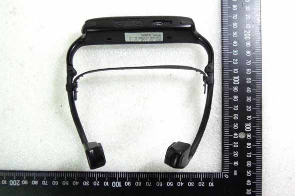
Headbones
Equipment Class
DSS - Part 15 Spread Spectrum Transmitter