2AAB5GC576069WIFI POWER BANK
ZHENJIANG SOLAR ELECTRONIC TECHNOLOGY CO., LTD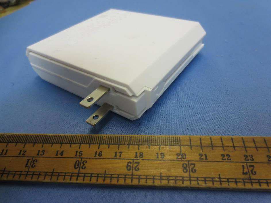
Click to zoom
Application Details
- Equipment Class
- DTS - Digital Transmission System
- Date of Grant
- Jul 06, 2013
- Application Purpose
- Original Equipment
- Date of Application
- Jul 06, 2013
- Equipment Note
- WIFI POWER BANK
- Frequency Range
- 2412.00000000 - 2462.00000000
- Country
- China
Documents & Files
Document Text
Text extracted from the exhibit documents filed with the FCC. Open a document above to read the original.
Users Manual
- 1 - WIFIPowerBank YourmobiledevicepartneriT-1010 UserManual Safety Warning:Changesor modificationsto this unitnot expresslyapprovedby the partyresponsiblefor compliancecouldvoid the user'sauthorityto operatethe equipment. NOTE:Thisequipmenthas beentestedand foundto complywiththe limitsfor a ClassB digitaldevice,pursuantto Part 15 of the FCCRules.Theselimitsare designedto providereasonableprotection againstharmfulinterferencein a residentialinstallation.Thisequipmentgenerates, usesandcanradiateradio frequencyenergyand, if not installedand usedin accordance with the instructions, maycauseharmfulinterference to radiocommunications. How ever , thereis no guaranteethatinterferencewill not occurin a particular installation.If this equipmentdoescauseharmfulinterferenceto radioor television reception,wh ich can be determinedby turningthe equipmentoff and on, the user is encouragedto try to correctthe interferenceby one or moreof the following measures: Reorientor relocatethe receivingantenna. Increasethe separation between the equipmentand receiver. Connectthe equipmentinto an outleton a circuitdifferentfromthat to which the rece iver is connected. Consultthe dealeror an experiencedradio/TVtechnicianfor help. Thisdevicecomplieswith Part15 of the FCCRules.Operation is subjectto the following tw o conditions: (1) this devicemaynot causeharmfulinterference,and (2) this devicemustaccept any interferencereceived, includinginterference that maycauseundesiredoperation. FCC RF Radiation Exposure Statement Caution: This Transmitter must be installed to provide a separation distance of at least 20 cm from all persons. -2- Chapter1: ProductAppearance BriefIntroduction: 1.USBchargingPort:Charge MobilePhoneor Tablet PC produ cts. 2.USBData Shar e Port: Plug the external USBflash on this port,MobilePhone/T ablet PC can READ/COPY/DELETEthe files in USBflash through App Software"U Client". 3.ResetButton:Res et System 4.RJ45LANport:Plugon LAN cable and accessto Internetautomatically. 5.AC Plug:Support110-240 V 50/60HzAC current inputfo r built-inLi batterycharging 6.PowerButton:Pre ss the butto n and no-releasefor se ve ra l seconds,unit will be pow eredon. Pressthe butto n againin the sameway , unit will be turnedoff. 7.BatteryIndicationLight:ThreeGreencolourLED lightsfor batteryleve l indication. Lightsflash during the batterycharging. Whenbatteryfull charged, all threeindicationlight on. 8.Built-inLi battery :4300mAhbatterycapacity, can be used to fully chargetwo iPhoneminimum. 2. USB Data Share 1. USBcharging 4. RJ45port 5. AC PLUG 6. Pow er Button 7. Batt ery Indication Light 8. 4300mAh RechargableLi batter yinside 3. Res et button 8. 4300mAh RechargableLi batter yinside -3- Chapter 2: APP Software Install 1) Enter App Store2) Search the App Software which name as "U Client" 3) Install App Software Uclient App Store Click Free Click Install Installing. ......... Install sucessfull y Search -4- Chapter 3: Wireless Router Connecting Search the wireless hot spot whichnames "CodeTek", then input the default password "12345678" to connect it. Chapter 4: USB Data Share Feature operation 1) Plug on the external USB flash onto the "DATA" USB port. Attention: USB flash file system must be FAT32 or ExFAT system. USB capacity 3TB maximum 2) After connect to wireless router successfully, active the App software "U Client", and it will come up the below Main Menu page Main Menu Description: (a)My U Drive: It means the External USB Flash pluging on the iT-1010 now. (b)My iPhone: It refers to iPhone(or iPad) which wirelessly connect to iT-1010 now (c)Setting: Router feature setting menu (d)About: Show iT-1010 product version number. -5- 3) Sub menu description (1) My U Drive Attention: User can click and playback the files under Video/Photo/Music/Document menu directly. But please make sure your iPhone/iPad have the right software to decode software for these files. iT-1010 do not have any decode system inside, itis only a wireless connecting bridge for your mobile service and external USB flash. Sub Menu Description: (a) Video All video format files will showunder this document automatically (b) Photo All photo format files will showunder this document automatically (c) Music All audio format files will showunder this document automatically (d) Document All TEXT format files will show under this documents automatically (e) Folder If users want to edit the files on USB, must enter "Document" Menu Edit files on USB (a) Click "FOLDER" document at first to enter sub menu (b) Click "disk1" document and then all the files on USB flash show out (c) Click "Manage Files" on the right up corner -6- (d) Select the files which you want to edit by tick the circle on right side (e) User can have these edit operations: "CHANGE FILE NAME" / "CREAT NEW DOCUMENT" / "COPY" / "MOVE" / "DELETE" (see remarks on left picture) CHANGE FILE NAME CREAT NEW DOCUMENT COPY MOVE DELETE Special instruction for "COPY" feature (a) When use click "COPY" button, it will switch to left side menu page automatically (b) Then click "My iPhone" option,enter the sub menu as left (c) Select the right document which you want to copy the file to, then click "Copy to here" on the right down corner, then the file has been copied to here successfully. -7- (2) My iPhone User may copy the file from iPhone/iPad to USB flash as well. Operation steps as below: 1) Enter My iPhone menu as below and select the certain document name which exist the file you want to copy to external USB flash. Remark: Normally there will exist Photo/Video files in the document names "Photo Library", because when you use iPhone/iPad camera to take photo/videos, Photo pictures or videos will be stored in "Photo Library" document automatically. 2) Click "Manage Files" and select the right file you want to copy to external USB flash -8- 3) Click "MY U Drive", then click "Copy to here", it will be done.
External Photos
External Photos
ID Label/Location Info
5mm 8mm POWER ONLY DATA RESET WAN ON/OFF FCC ID: 2AAB5GC576069 This device complies with Part 15 of the FCC Rules.Operation is s u bject to the following two conditions: (1) this device may not cause harmful interference, and (2) this device must accept any interference received, including interference that may cause undesired operation. PRODUCT NAME: WIFI POWER BANKiT1010, ADMINISTRATION IP: 192.168.99.1 802.11b/g/n INPUT: AC IN 110V-240V 50/60Hz 15W, USER NAME: admin,PASSWORD: admin 5mm 8mm CONFORMS TO UL STD. 60950-1 87mm 6mm
Internal Photos
Internal Photos
RF Exposure Info
FCC ID: 2AAB5GC576069 1 INTERTEK TESTING SERVICES RF Exposure The Equipment Under Test (EUT) is a WIFI POWER BANK with internal WiFi function operating at 2412-2462MHz for 802.11b/g/n-HT20, 11 channels with 5MHz channel spacing and 2422-2452MHz for 802.11n-HT40, 7 channels with 5MHz channel spacing. The EUT can be powered by DC 3.7V (1 x 3.7V rechargeable battery) or AC 110V ~ 240V, 50/60Hz . For more detailed features description, please refer to the user’s manual. Antenna Type: Integral Antenna. Antenna Gain: 0dBi Modulation Type: BPSK, QPSK, 16QAM, 64QAM, CCK, DQPSK, DBPSK The nominal conducted output power specified: 17dBm +/-3dB. According to the KDB 447498: The maximum peak conducted output power for the EUT is 19.46dBm in the frequency 2412MHz (802.11g) which is within the product variation. The minimum peak conducted output power for the EUT is 14.34dBm in the frequency 2462MHz (802.11b) which is within the production variation. According to FCC Part 2.1091, this unlicensed transmitting devices is categorically excluded from routine environmental evaluation for RF exposure prior to equipment authorization or use, According to the KDB 447498 and OET 65, the simple calculation as below: For Maximum Permissible Exposure (MPE) evaluation of the product, the maximum power density at 20 cm from this transmitter shall be less than the General Population / Uncontrolled MPE limit in OET Bulletin 65. The maximun conducted output power specified is 20dBm = 100mW The source- based time-averaging conducted output power = 100 * Duty factor mW= 100 mW From above data, the exposed power density at a distance (R) of 20cm from the center of radiation of the antenna can be calculated according to OET Bulletin 65 as follow: = 100 mW / 4 πR^2 = 0.0199 mW/cm^2 FCC ID: 2AAB5GC576069 2 INTERTEK TESTING SERVICES The MPE limit is 1.0 mWcm-2 for general population and uncontrolled exposure in the WiFi frequency range according to FCC Part 1.1310. As the measured power density at 20cm from the transmitter is lower than the MPE limit, the compliance to the MPE limit can be ensured by indicating the minimum 20cm separation between the transmitter's radiating structure and body of the user or nearby persons. Transmitter Duty Cycle Calculation The EUT transmit continuously during the test, the duty cycle is 1. The following RF exposure statement is proposed to be included in the user manual: “FCC RF Radiation Exposure Statement Caution: This Transmitter must be installed to provide a separation distance of at least 20 cm from all persons.”
Test Report
• The test results reported in this test report shall refer only to the sample actually tested and shall not refer or be deemed to refer to bulk from which such a sample may be said to have been obtained. • This report is for the exclusive use of Intertek's Client and is provided pursuant to the agreement between Intertek and its Client. Intertek's responsibility and liability are limited to the terms and conditions of the agreement. Intertek assumes no liability to any party, other than to the Client in accordance with the agreement, for any loss, expense or damage occasioned by the use of this report. Only the Client is authorized to copy or distribute this report. Any use of the Intertek name or one of its marks for the sale or advertisement of the tested material, product or service must first be approved in writing by Intertek. The observations and test results referenced from this report are relevant only to the sample tested. This report by itself does not imply that the material, product, or service is or has ever been under an Intertek certification program. • For Terms And Conditions of the services, it can be provided upon request. • The evaluation data of the report will be kept for 3 years from the date of issuance. TRF no.: FCC 15C_Tx_b Intertek Testing Services Shenzhen Ltd. Kejiyuan Branch 6F, D Block, Huahan Building, Langshan Road, Nanshan District, Shenzhen, P. R. China Tel: (86 755) 8601 6288 Fax: (86 755) 8601 6751 Website: www.china.intertek-etlsemko.com ZHENJIANG SOLAR ELECTRONIC TECHNOLOGY CO., LTD. Application For Certification FCC ID: 2AAB5GC576069 WIFI POWER BANK Model: iT1010 Additional Models: iT1020, iT1030 Trademark: digitrex, i-Trav, dqv WiFi Transceiver Report No.: 130510032SZN-001 We hereby certify that the sample of the above item is considered to comply with the requirements of FCC Part 15, Subpart C for Intentional Radiator, mention 47 CFR [10-1-12] Prepared and Checked by: Approved by: Sign on file Chris Chen Engineer Andy Yan Project Engineer Date: June 14, 2013 INTERTEK TESTING SERVICE TRF no.: FCC 15C_TX_b FCC ID: 2AAB5GC576069 Report No.: 130510032SZN-001 i LIST OF EXHIBITS INTRODUCTION EXHIBIT 1: Summary of Tests EXHIBIT 2: General Description EXHIBIT 3: System Test Configuration EXHIBIT 4: Measurement Results EXHIBIT 5: Equipment Photographs EXHIBIT 6: Product Labeling EXHIBIT 7: Technical Specifications EXHIBIT 8: Instruction Manual EXHIBIT 9: Confidentiality Request EXHIBIT 10: Miscellaneous Information EXHIBIT 11: Test Equipment List INTERTEK TESTING SERVICES TRF no.: FCC 15C_TX_b FCC ID: 2AAB5GC576069 Report No.: 130510032SZN-001 ii MEASUREMENT/TECHNICAL REPORT ZHENJIANG SOLAR ELECTRONIC TECHNOLOGY CO., LTD. MODEL: iT1010 Additional Models: iT1020, iT1030 FCC ID: 2AAB5GC576069 This report concerns (check one) Original Grant X Class II Change Equipment Type: DTS - Part 15 Digital Transmission Systems (WiFi transmitter portion) Deferred grant requested per 47 CFR 0.457(d)(1)(ii)? Yes No X If yes, defer until : date Company Name agrees to notify the Commission by: date of the intended date of announcement of the product so that the grant can be issued on that date. Transition Rules Request per 15.37? Yes No X If no, assumed Part 15, Subpart C for intentional radiator - the new 47 CFR [10-01-12 Edition] provision. Report prepared by: Andy Yan Intertek Testing Services Shenzhen Ltd. Kejiyuan Branch 6F, Block D, Huahan Building, Langshan Road, Nanshan District, Shenzhen, P. R. China Phone: (86 755) 8614 0633 Fax: (86 755) 8614 6751 INTERTEK TESTING SERVICES TRF no.: FCC 15C_TX_b FCC ID: 2AAB5GC576069 Report No.: 130510032SZN-001 iii Table of Contents 1.0 Summary of test results...............................................................................2 2.0 General Description................................................................................................4 2.1 Product Description ....................................................................................... 4 2.2 Related Submittal(s) Grants .......................................................................... 4 2.3 Test Methodology.......................................................................................... 4 2.4 Test Facility ................................................................................................... 4 3.0 System Test Configuration ................................................................................. 6 3.1 Justification ................................................................................................... 6 3.2 EUT Exercising Software............................................................................... 6 3.3 Details of EUT and Description of Peripherals ............................................... 7 3.4 Measurement Uncertainty.............................................................................. 7 3.5 Equipment Modification ................................................................................. 7 3.6 Support Equipment List and Description....................................................... 7 4.0 Measurement Results.............................................................................................9 4.1 Maximum Conducted Output Power at Antenna Terminals............................ 9 4.2 Minimum 6dB RF Bandwidth ....................................................................... 11 4.3 Maximum Power Density ................................................................................19 4.4 Out of Band Conducted Emissions ...............................................................27 4.5 Out of Band Radiated Emissions ................................................................. 52 4.6 Transmitter Radiated Emissions in Restricted Bands................................... 53 4.7 Field Strength Calculation............................................................................ 54 4.8 Radiated Spurious Emission......................................…
Text truncated - open the document above for the full version.
Test Setup Photos
Radiated Emission
Test Setup Photos
Conducted Emission
Contact Information
Applicant
XIAO LIU
Technical Contact
Intertek Testing Services Shenzhen Ltd. Kejiyuan BShawn Xing
[email protected](86-755) 8614 0603
6F, D Block, Huahan Building, Langshan Road · Shenzhen · China
Non-Technical Contact
Intertek Testing Services Shenzhen Ltd. Kejiyuan BShawn Xing
[email protected](86-755) 8614 0603
Test Firm
Intertek Testing Services Shenzhen Ltd.Shawn Xing
Technical Specifications
| # | Rule Parts | Frequency Range | Power Output |
|---|---|---|---|
| 1 | 15C | 2.41 GHz - 2.46 GHz | 88.31 mW |