2AABVWVOM74QVOYAGER TOUGHCAM DIGITAL WIRELESS OBSERVATION SYSTEM
ASA ELECTRONICS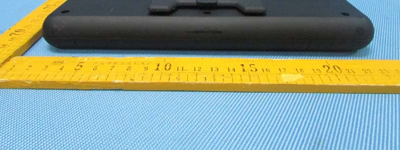
Click to zoom
Application Details
- Equipment Class
- DSS - Part 15 Spread Spectrum Transmitter
- Date of Grant
- Jul 17, 2013
- Application Purpose
- Original Equipment
- Date of Application
- Jul 17, 2013
- Equipment Note
- VOYAGER TOUGHCAM DIGITAL WIRELESS OBSERVATION SYSTEM
- Frequency Range
- 2402.00000000 - 2480.00000000
- Company
- ASA ELECTRONICS
- Country
- United States
Documents & Files
Document Text
Text extracted from the exhibit documents filed with the FCC. Open a document above to read the original.
Users Manual
TOUGH CAM Version 1.0 Model: WVOS7MDCL1Q PLEASE READ CAREFULLY AND SAVE This manual contains important information about this product’s operation. If you are installing this product for others, you must have this manual – or a copy – with the end user. INTRODUCTION KEY FEATURES: • The ToughCam supports up to 200 meter of Secured video transmissions • The 7” LCD wireless monitor supports up to VGA@25FPS (Single Camera); or QVGA@20fps (Multiple Camera) • Expandable up to 4 camera connection. • Wireless monitor support CH auto-switch functions, with a signal trigger cable connect from the monitor to the power switch of the rear-gear warning light; whenever the rear-gear is selected, wireless monitor will auto-switch to CH1 for rear-viewing, and switch back to previous selected CH when R-gear is no longer selected. • Camera supports DC Power input from 12~24V, and monitor supports DC Power input from 12~24V. This system can be installed to any type of car battery. • Individual Camera Brightness Setting is available for different user installation environments. • Video from each connected camera can be displayed in normal mode or Mirror mode (The “M” Sign will be display in the screen) individually. • The monitor supports remote controller for easy operation. IMPORTANT SAFETY PRECAUTIONS Damages caused by non-compliance with this operating manual will void the warranty! We will not assume any liability for damages to items or persons caused by improper handling or non-compliance with the safety notices! Any warranty claim will be null and void in such cases. 1. Do not drop, puncture or disassemble the camera; otherwise the warranty will be voided. 2. Avoid all contact with water, and dry hands before using. 3. Never tug on the power cords. Use the plug to unplug it from the wall outlet. 4. Do not expose the camera to high temperature or leave it in direct sunlight. Doing so may damage the camera or cause camera temporary malfunction. 5. Use the devices with care. Avoid pressing hard on the camera body. 6. For your own safety, avoid using the camera or power off the camera when there is a storm or lightning. 7. Remove the power adapter during long periods between usages. 8. Use only the accessories and power adapters supplied by the manufacturer. 9. To meet the regulations pertaining to parental responsibility, keep the devices out of the reach of infants. 10. Check power cables, do not get crushed or damaged by sharp edges whenever the devices are in operation. FCC Compliance Statement: This device complies with Part 15 of the FCC rules. Operation is subjected to the following two conditions: (1) this device may not cause harmful interference, and (2) this device must accept any interference received, including interference that may cause undesired operation. Products with CE Marking comply with EMC Directive (2004/108/EC); Low Voltage Directive (73/23/EEC); R&TTE(1999/5/EC); ROHS Directive (2011/65/EU) issued by the Commission of the European Community. Compliance with these directives implies conformity to the following European Norms: EMC: EN 301 489 LVD: EN 60950 Radio: EN 300 328 FCC/CE WARNING This equipment has been tested and found to comply with limits for a Class B digital device, pursuant to Part 15 of the FCC rules and ETSI(EN) 300328. These limits are designed to provide reasonable protection against harmful interference in residential installations. This equipment generates, uses, and can radiate radio frequency energy, and if not installed and used in accordance with the instructions, may cause harmful interference to radio communications. However, there is no guarantee that interference will not occur in a particular installation. If this equipment does interference to radio or television equipment reception, which can be determined by turning the equipment off and on, the user is encouraged to try to correct the interference by one or more of the following measures: -Reorient or relocate the receiving antenna.-Move the equipment away from the receiver.-Plug the equipment into an outlet on a circuit different from that to which the receiver is connected.-Consult the dealer or an experienced radio/television technician for additional suggestions. You are cautioned that any change or modifications to the equipment not expressly approved by the party responsible for compliance could void your authority to operate such equipment. DISPOSAL If the camera system no longer functions or can no longer be repaired, it must be disposed of according to the valid statutory regulations. Disposal of spent batteries/accumulators: You are required by law (Battery Ordinance) to return all spent batteries and accumulators. Disposing of spent batteries/accumulators with common household waste is prohibited! Batteries/accumulators that contain hazardous substances are marked with the symbols on the side. These symbols indicate that it is prohibited to dispose of these batteries/accumulators in the household waste. The abbreviations for the respective heavy metals are: Cd=cadmium, Hg=mercury, Pb=lead. You can return spent batteries and accumulators that can no longer be charged to the designated collection points in your community, outlets or wherever batteries or accumulators are sold. Following these instructions will allow you to fulfill the legal requirements and contribute to the protection of our environment! To comply with the FCC/CE limitation for class B device and to avoid interference, please follow manufacturer’s installation instruction. KIT CONTENT Image Contents EA Wireless video camera with mounting bracket 1 EA 5dBi antennas 2 EA 9.5 ft. cable and mounting bracket 2 EA Wireless 7” LCD monitor 1 EA Monitor mount 1 EA Remote control for the monitor 1 EA Cigarette adaptor for the monitor 1 EA Hardwire cable for monitor (screw bag x 1, DC power cable x 1, trigger cable x1) 1 EA User’s Manual 1 EA INSTALLING THE CAMERA With fixed power source 1. Choose a place at rear bumper you wish to …
Text truncated - open the document above for the full version.
External Photos
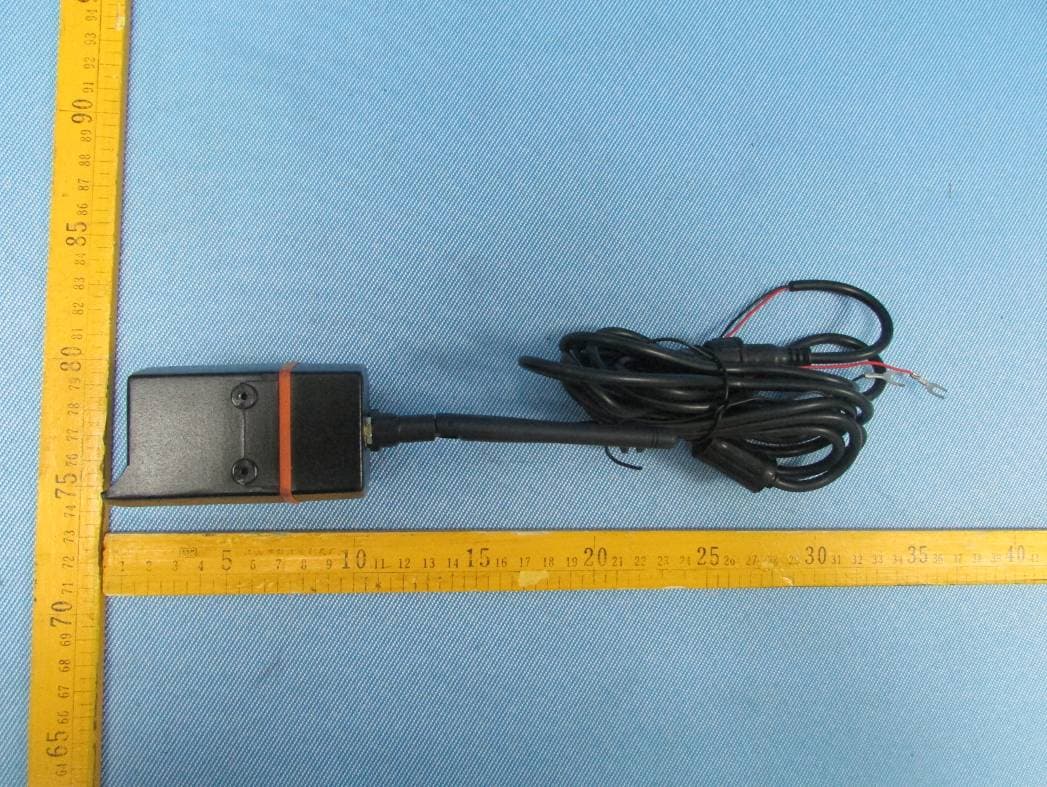
Reference No.: WTD13S0604445E Page 87 of 94 Waltek Services (Shenzhen) Co.,Ltd. http://www.waltek.com.cn 19 Photographs - Constructional Details 19.1 EUT –Appearance View 5dBi ANT. With 3m 5dBi ANT. With 9m Cable 3dBi ANT. Reference No.: WTD13S0604445E Page 88 of 94 Waltek Services (Shenzhen) Co.,Ltd. http://www.waltek.com.cn Reference No.: WTD13S0604445E Page 89 of 94 Waltek Services (Shenzhen) Co.,Ltd. http://www.waltek.com.cn Reference No.: WTD13S0604445E Page 90 of 94 Waltek Services (Shenzhen) Co.,Ltd. http://www.waltek.com.cn
ID Label/Location Info
Page: 1 of 1 2 FCC Label FCC Label Sample for model: WVOM74Q The Label must not be a stick-on paper. The Label on these products must be permanently affixed to the product and readily visible at the time of purchase and must last the expected lifetime of the equipment not be readily detachable. FCC ID: 2AABVWVOM74Q This device complies with Part 15 of the FCC Rules. Operation is subject to the following two conditions: (1) this device may not cause harmful interference, and (2) this device must accept any interference received, including interference that may cause undesired operation.
ID Label/Location Info
Page: 1 of 1 2 FCC Label FCC Label Sample for model: WVOM74Q FCC ID: 2AABVWVOM74Q This device complies with Part 15 of the FCC Rules. Operation is subject to the following two conditions: (1) this device may not cause interference, and (2) this device must accept any interference, including interference that may cause undesired operation of the device. The Label must not be a stick-on paper. The Label on these products must be permanently affixed to the product and readily visible at the time of purchase and must last the expected lifetime of the equipment not be readily detachable.
Internal Photos
Page: 1 of 4 RF Module 2.1 EUT – Open View Antenna Reference No.: WTD13S0604444E Page 2 of 4
Internal Photos
Reference No.: WTD13S0604444E Page 3 of 4 2.2 RF –Module View Reference No.: WTD13S0604444E Page 4 of 4
Test Report
Reference No.: WTD13S0604445E Page 1 of 48 FCC TEST REPORT Waltek Services (Shenzhen) Co.,Ltd. http://www.waltek.com.cn FCC ID :2AABVWVOM74Q Applicant : ASA ELECTRONICS Address : 2602 MARINA DRIVE ELKHART, Indiana 46514 Manufacturer : ASA ELECTRONICS Address : 2602 MARINA DRIVE ELKHART, Indiana 46514 Equipment Under Test (EUT) : Product Name : VOYAGER TOUGHCAM DIGITAL WIRELESS OBSERVATION SYSTEM Model No. : WVOM74Q Rules : FCC CFR47 Part 15 Section 15.247:2010 Date of Test : June 24~26, 2013 Date of Issue : July 08, 2013 Test Result : PASS Remark: * The sample described above has been tested to be in compliance with the requirements of ANSI C63.4:2003. The test results have been reviewed and comply with the rules listed above and found to meet their essential requirements. The results shown in this test report refer only to the sample(s) tested, this test report cannot be reproduced, except in full, without prior written permission of the company. The report would be invalid without specific stamp of test institute and the signatures of compiler and approver. Prepared By: Waltek Services (Shenzhen) Co., Ltd. 1/F, Fukangtai Building, West Baima Rd., Songgang Street, Baoan District, Shenzhen 518105, China Tel: +86-755-83551033 Fax: +86-755-83552400 Compiled by: Approved by: Maikou Zhang / Project Engineer Philo Zhong / Manager Reference No.: WTD13S0604445E Page 2 of 87 Waltek Services (Shenzhen) Co.,Ltd. http://www.waltek.com.cn 2 Test Summary Test Items Test Requirement Result Conduct Emission 15.207 N/A Radiated Emissions 15.205(a) 15.209 15.247(d) PASS 20dB Bandwidth 15.247(a)(1) PASS Duty Cycle 15.35 PASS Band Edge 15.247(d) PASS Maximum Peak Output Power 15.247(b)(1) PASS Frequency Separated 15.247(a)(1) PASS Hopping Channel Number 15.247(a)(1)(iii) PASS Dwell time 15.247(a)(1)(iii) PASS Antenna Requirement 15.203 PASS Maximum Permissible Exposure (Exposure of Humans to RF Fields) 1.1307(b)(1) PASS Reference No.: WTD13S0604445E Page 3 of 87 Waltek Services (Shenzhen) Co.,Ltd. http://www.waltek.com.cn 3 Contents Page 1 COVER PAGE................................................................................................................................ 1 2 TEST SUMMARY.......................................................................................................................................2 3 CONTENTS.................................................................................................................................................3 4 GENERAL INFORMATION.......................................................................................................................5 4.1 GENERAL DESCRIPTION OF E.U.T...................................................................................................... 5 4.2 DETAILS OF E.U.T............................................................................................................................... 5 4.3 TEST FACILITY...................................................................................................................................... 5 4.4 TEST LOCATION.................................................................................................................................... 5 5 EQUIPMENT USED DURING TEST.......................................................................................................6 5.1 EQUIPMENTS LIST................................................................................................................................6 5.2 MEASUREMENT UNCERTAINTY............................................................................................................ 6 5.3 TEST EQUIPMENT CALIBRATION.......................................................................................................... 6 6 CONDUCTED EMISSION.........................................................................................................................7 7 RADIATED EMISSIONS............................................................................................................................8 7.1 EUT OPERATION :................................................................................................................................8 7.2 TEST SETUP......................................................................................................................................... 9 7.3 SPECTRUM ANALYZER SETUP........................................................................................................... 10 7.4 TEST PROCEDURE............................................................................................................................. 11 7.5 CORRECTED AMPLITUDE & MARGIN CALCULATION.......................................................................... 11 7.6 SUMMARY OF TEST RESULTS............................................................................................................ 12 8 DUTY CYCLE............................................................................................................................................38 8.1 TEST PROCEDURE............................................................................................................................. 38 8.2 TEST RESULT..................................................................................................................................... 38 9 BAND EDGE MEASUREMENT.............................................................................................................40 9.1 TEST RESULT:.................................................................................................................................... 41 10 20 DB BANDWIDTH MEASUREMENT................................................................................................65 10.1 TEST PROCEDURE:........................................................................................................................ 65 10.2 TEST RESULT:...............................…
Text truncated - open the document above for the full version.
Test Setup Photos
Reference No.: WTD13S0604445E Page 85 of 87 Waltek Services (Shenzhen) Co.,Ltd. http://www.waltek.com.cn 18 Photographs – Test Setup 18.1 Photograph –Radiated Emissions Test Setup Below 30MHz 30MHz-1GHz Reference No.: WTD13S0604445E Page 86 of 87 Waltek Services (Shenzhen) Co.,Ltd. http://www.waltek.com.cn Above 1GHz
Contact Information
Applicant
Julia Willis
Test Firm
Waltek Services(Shenzhen) Co., Ltd.Philo zhong
Technical Specifications
| # | Rule Parts | Frequency Range | Power Output |
|---|---|---|---|
| 1 | 15C | 2.40 GHz - 2.48 GHz | 19.00 mW |
Other Applications from ASA ELECTRONICS
2AABVWVCMSQ1B
Jul 17, 2013VOYAGER TOUGHCAM DIGITAL WIRELESS OBSERVATION SYSTEM
Equipment Class
DSS - Part 15 Spread Spectrum Transmitter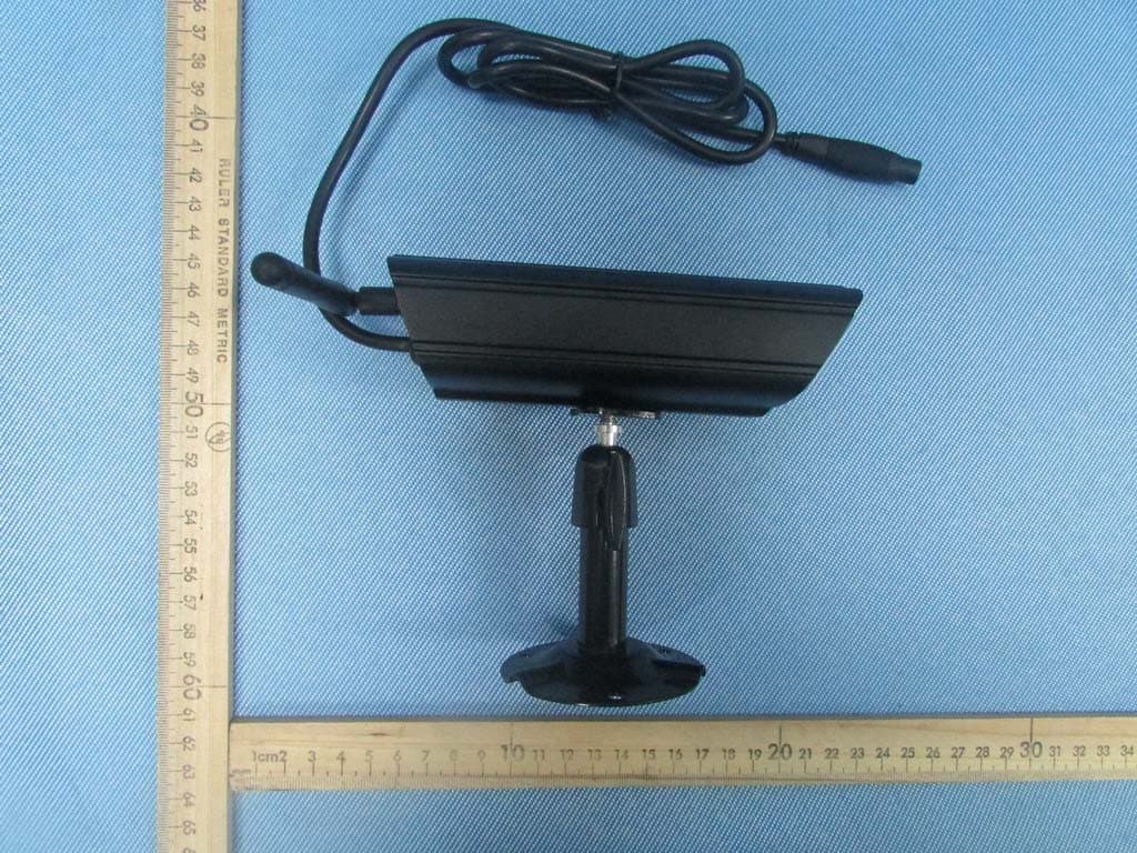
2AABVBARNVIEWCAM
Jul 04, 2013BARNVIEW DIGITAL WIRELESS SURVEILLANCE SYSTEM
Equipment Class
DSS - Part 15 Spread Spectrum Transmitter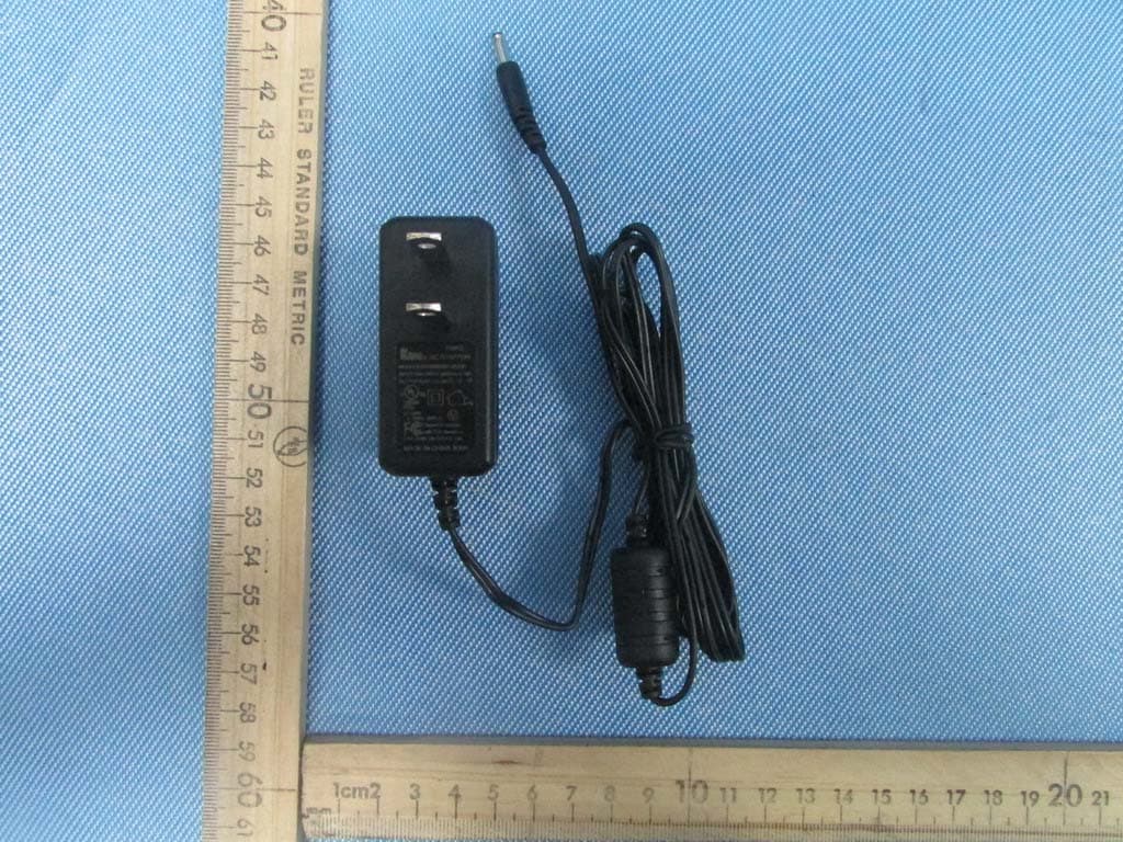
2AABVBARNVIEWMON
Jul 04, 2013BARNVIEW DIGITAL WIRELESS SURVEILLANCE SYSTEM
Equipment Class
DSS - Part 15 Spread Spectrum Transmitter