2AADS-SOUNDSOLEACTIVE SPEAKER
OSD Audio.Inc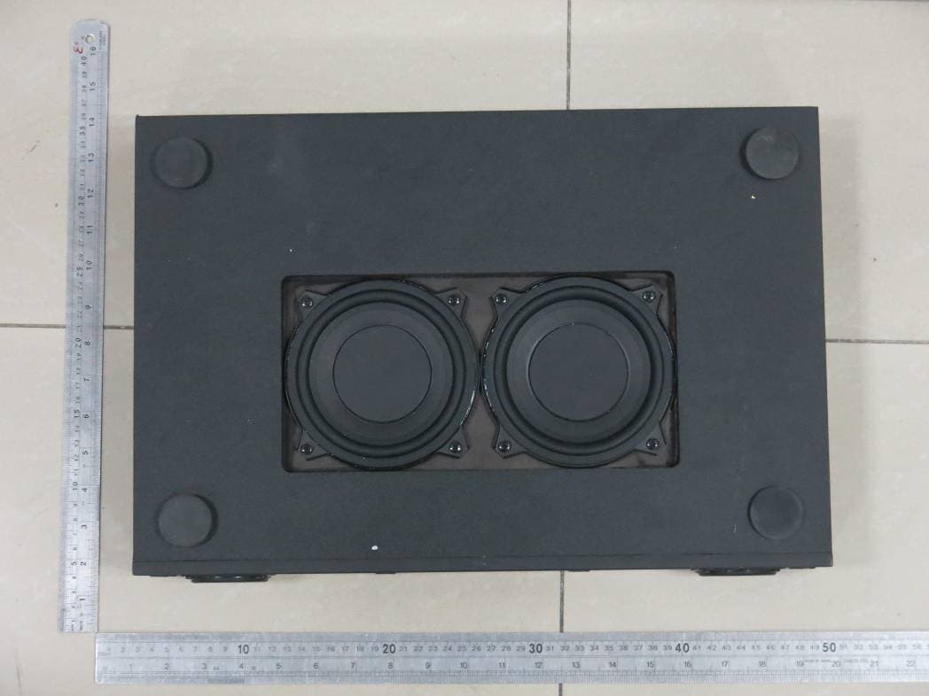
Click to zoom
Application Details
- Equipment Class
- DTS - Digital Transmission System
- Date of Grant
- Nov 26, 2013
- Application Purpose
- Original Equipment
- Date of Application
- Nov 26, 2013
- Equipment Note
- ACTIVE SPEAKER
- Frequency Range
- 2402.00000000 - 2480.00000000
- Company
- OSD Audio.Inc
- Country
- United States
Documents & Files
Document Text
Text extracted from the exhibit documents filed with the FCC. Open a document above to read the original.
Users Manual
Desk-Top/Table-Top All in One Sound System OSD Audio · 775 Columbia Street · Brea, CA 92821 · Tel: (562) 697-2600 · www.osdaudio.com Page 1 OSD Audio · 775 Columbia Street · Brea, CA 92821 · Tel: (562) 697-2600 · www.osdaudio.com Page 2 OSD Audio · 775 Columbia Street · Brea, CA 92821 · Tel: (562) 697-2600 · www.osdaudio.com Page 3 Includes 1 - Stereo SoundSole 2.1 1 - IR Remote Control 1 - Lithium Battery (3V, CR2025) 1 - Stereo RCA Patch Cable 1 - Digital Optical Patch Cable 1 - AC Power Supply OSD Audio · 775 Columbia Street · Brea, CA 92821 · Tel: (562) 697-2600 · www.osdaudio.com Page 4 Congratulations and thank you for purchasing OSD AUDIO SOUNDSOLE 2.1 Desk/Table-Top All in One System. The OSD AUDIO SOUNDSOLE 2.1 greatly enhances the sound quality of today’s flat screen LED, LCD and Plasma TVs without having to add a lot of speakers. A single speaker system that requires very little space, the SOUNDSOLE 2.1 can be installed below or in front of a high definition TV or inside a cabinet. You’ll enjoy simulated surround sound from a single, space- saving cabinet with deep, enveloping bass without bulky speakers or amps. The OSD AUDIO SOUNDSOLE 2.1 easily connects to inputs on today’s flat panel TVs and digital music players and even syncs to almost any Bluetooth audio device. OSD Audio SOUND SOLE 2.1 FRONT PANEL 1. STATUS LED - (Behind front panel lens.) One multi-color LED. This LED will illuminate red/blue and flash in different modes to indicate changes in the SOUNDSOLE 2.1operational status. SOLID RED - OFF (Standby). Power cord is connected and AC switch is turned ON, but the SOUNDSOLE 2.1 is OFF. SOLID BLUE – ON – OSD AUDIO SOUNDSOLE 2.1 is ON. SINGLE BLUE FLASH - Confirms receiving an IR command from the OSD AUDIO SOUNDSOLE 2.1 Remote for changes to Treble/Bass, EQ Reset, Simulated Surround (SR), single Volume UP/DOWN command, initiating output of the Bluetooth Connection Code. RAPID BLUE FLASH - Confirms receiving a continuous IR stream from the SOUNDSOLE 2.1 Remote for ramping volume UP/DOWN. Rapid blue flash also indicates the SOUNDSOLE 2.1 is in Bluetooth pairing mode. SLOW BLUE FLASH - Audio Mute. Audio signal to the speakers is turned OFF. TWO BLUE FLASHES; DELAY - Bluetooth input is selected and no Bluetooth device is connected or it is out of range. 2. IR SENSOR - (Behind front panel lens.) The IR Sensor ‘sees’ the IR control commands output from the SOUNDSOLE 2.1 IR Remote Control when buttons are pressed on the remote for armchair control of the SOUNDSOLE 2.1. This sensor must be unobstructed for direct line-of-sight to the remote, or the remote will not be able to control the SOUNDSOLE 2.1. 1 2 Page 5 OSD Audio · 775 Columbia Street · Brea, CA 92821 · Tel: (562) 697-2600 · www.osdaudio.com DIGITAL FIBER OPTIC INPUT - One Digital Fiber Optic port. Connect to the Digital Optical OUT on a TV or other Digital source. This input is selected by pressing the Source button on the OSD AUDIO SOUNDSOLE 2.1 IR Remote. NOTE: The audio output of a TV, Blu-ray Disc player, game console, or DVD player connected to the SOUNDSOLE 2.1 via Coaxial Digital must be set to PCM in the source’s setup. Please see the device’s Owner’s Manual for details. RCA ANALOG STEREO AUDIO INPUT - Two RCA jacks. Connect to the L & R Line Level Audio OUT on a TV or other source. This input is selected by pressing the AUX button on the OSD AUDIO SOUNDSOL 2.1 IR Remote. AC INPUT- Universal power connector. Automatically selects AC voltage for a given region. Connect to the included 2-conductor AC Power Cord. After all audio connections have been made and confirmed, plug the power cord into an un-switched AC Outlet to power the OSD AUDIO SOUNDSOLE 2.1. DOWN FIRING SUBWOOFER - The OSD AUDIO SOUNDSOLE 2.1 bottom panel features two 5-1/4” subwoofers, one of the Drivers is active driven by a 30 Watt Low Pass Digital Class D Amplifier. The second 5.25” driver is a Passive radiator helping to tune the enclosure. When handling the SOUNDSOLE 2.1 be careful not to grab or hold the cabinet bottom where the woofers are located to prevent damaging the woofers. Also take care to not set the cabinet down on anything but a flat surface clear of obstructions. When placing the OSD AUDIO SOUNDSOLE 2.1 PLATFORM on a shelf or stand, be sure there are no objects under the cabinet that will damage or block the woofers and check to make sure there are no objects on the sides of the cabinet that will block the space under the SOUNDSOLE 2.1. Blocking this space will reduce overall bass performance. 3.5MM AUX STEREO AUDIO INPUT – A Single 3.5mm Stereo; Connect to the Headphone Jack of any iPod, iPad, Laptop or PC computer. This input is selected by pressing the Source button on the OSD AUDIO SOUNDSOLE 2.1 IR Remote. Use with devices not Bluetooth enabled, signal is Analog. Multi Voltage Switching Supply Dual 5.25” Down-Firing Sub-Woofer (1 Active, 1 Passive) Powered by 1 x 30 Watt Digital Low pass Power Amp Page 6 IR REMOTE CONTROL 1. POWER - Press this button to turn the SOUNDSOLE 2.1 ON/OFF. 2. SRC; SOURCE- Press to select a connected source. The SOUNDSOLE 2.1 Front Panel Status LED will flash once to indicate a change in input selection. LINE IN1, AUX – 3.5mm input, from Headphone Jack ANALOG connection LINE IN2, RCA – Left and Right Signal Level Stereo RCA Input, ANALOG. Optical LINE IN – Digital Fiber Optic Input 3. VOLUME -/+ Press VOL (-) to reduce volume. Press VOL (+) to increase volume. 4. DSP Effect – Advanced Digital Signal Processing which creates simulated surround sound from a stereo speaker configuration. This will dramatically open up the sound stage making the appear to be coming from all over the room. There are two choices for DSP settings. Typically you would use the Cinematic setting when watching a Video, Movie or Television show. The Studio setting is recommended when listing to a 2 channel music source but does not guarantee better sound but just different. It then comes down to a personal preference to the l…
Text truncated - open the document above for the full version.
Cover Letter(s)
OSD Audio Inc FCC Authorization Letter We, (the approval holder) Company name OSD Audio Inc Addresss 775.columbia st,brea CA92821 City CA92821 Country United States declare that the following representative (agent): Name (person) Sam Lv Company name DONGGUAN EMTEK CO., LTD. Addresss No.281, Guantai Road, Nancheng District, City Dongguan Country China is hereby authorized to apply the following equipment for certification on our behalf: Product Description ACTIVE SPEAKER Type or Model(s) SOUNDSOLE 2.1 Tradename or Brand(s) OSD AUDIO
Cover Letter(s)
OSD Audio Inc FCC Confidentiality Request To the FCC and FCC TCB handling this application for certification Pursuant to 47 CFR Section 0.459(a) & (b), we, (the applicant / grantee) Company name OSD Audio Inc Addresss 775.columbia st,brea CA92821 City CA92821 Country United States request non-disclosure and confidential treatment for our certification under: Grantee Code Product Number FCC ID: 2AADS -SOUNDSOLE of the following materials submitted within this certification application: (please cross what is applicable, or add other documents) √ Operational Description √ Block Diagrams √ Schematics Diagrams √ Bill of Materials Above materials contain secrets, proprietary and technical information, which would customarily be guarded from competitors under 47 CFR, section 0.457(d)(2). Disclosure or publication or any portion of this company confidential material to other parties could cause substantial competitive harm and provide unjustified benefits for competitors. We understand that pursuant to 47 CFR section 0.457(d)(1)(ii) disclosure of the applicant and all accompanying documentation will not be made before the date of the grant.
ID Label/Location Info
240 5 5 2AADS-SOUNDSOLE A1 受控图面 部品料号 面板丝印图2013/11/15 1:1 240 5 5 2AADS-SOUNDSOLE 2.1
Test Report
TRF No. FCC Part 15.247/A Page 1 of 47 Report No. KAD131009008E Rev1.0 ELECTROMAGNETIC EMISSIONS COMPLIANCE REPORT INTENTIONAL RADIATOR CERTIFICATION TO FCC PART 15 SUBPART C REQUIREMENT OF ACTIVE SPEAKER MODEL No.: SOUNDSOLE 2.1 BRAND NAME: OSD AUDIO FCC ID: 2AADS-SOUNDSOLE REPORT NO: KAD131009008E ISSUE DATE: November 25, 2013 Prepared for OSD AUDIO.Inc 775. columbia st, brea CA92821 Prepared by DONGGUAN EMTEK CO., LTD. No.281, Guantai Road, Nancheng District, Dongguan, Guangdong, China TEL: 86-769-22807078 FAX: 86-769-22807079 TRF No. FCC Part 15.247/A Page 2 of 47 Report No. KAD131009008E Rev1.0 VERIFICATION OF COMPLIANCE Applicant: OSD AUDIO.Inc 775.columbia st,brea CA92821 Manufacturer: Dongguan Tristar Electronic Co.,Ltd. NO.24A DongXing Ave south, ZhenXingWei, TangXia Town, DongGuan City 523710, China. Product Description: ACTIVE SPEAKER Brand Name: OSD AUDIO Model Number: SOUNDSOLE 2.1 File Number: KAD131009008E Date of Test: October 09, 2013 to November 13, 2013 We hereby certify that: The above equipment was tested by DONGGUAN EMTEK CO., LTD. The test data, data evaluation, test procedures, and equipment configurations shown in this report were made in accordance with the procedures given in ANSI C63.4 (2009) and the energy emitted by the sample EUT tested as described in this report is in compliance with conducted and radiated emission limits of FCC Rules Part 15.247(2012). The test results of this report relate only to the tested sample identified in this report. Approved By Sam.Lv / Q.A. Manager DONGGUAN EMTEK CO., LTD. TRF No. FCC Part 15.247/A Page 3 of 47 Report No. KAD131009008E Rev1.0 Modified History Rev. Summary Date of Rev. Report No. V1.0 Original Report 2013-11-25 KAD131009008E TRF No. FCC Part 15.247/A Page 4 of 47 Report No. KAD131009008E Rev1.0 Table of Contents 1. GENERAL INFORMATION............................................................................................................6 1.1 PRODUCT DESCRIPTION................................................................................................................... 6 1.2 TEST METHODOLOGY....................................................................................................................... 7 1.3 SPECIAL ACCESSORIES.................................................................................................................... 7 1.4 EQUIPMENT MODIFICATIONS............................................................................................................ 7 1.5 TEST FACILITY................................................................................................................................. 7 2. SYSTEM TEST CONFIGURATION...............................................................................................8 2.1 EUT CONFIGURATION...................................................................................................................... 8 2.2 EUT EXERCISE................................................................................................................................8 2.3 TEST PROCEDURE........................................................................................................................... 8 2.4 CONFIGURATION OF TESTED SYSTEM.............................................................................................. 9 3. DESCRIPTION OF TEST MODES..............................................................................................10 4. CONDUCTED EMISSIONS TEST...............................................................................................11 4.1 MEASUREMENT PROCEDURE: ........................................................................................................ 11 4.2 TEST SET-UP (BLOCK DIAGRAM OF CONFIGURATION)................................................................... 11 4.3 MEASUREMENT EQUIPMENT USED: ................................................................................................ 11 4.4 CONDUCTED EMISSION LIMIT......................................................................................................... 12 4.5 MEASUREMENT RESULT:................................................................................................................ 12 4.6 CONDUCTED MEASUREMENT PHOTOS: .......................................................................................... 15 5. RADIATED EMISSION TEST......................................................................................................16 5.1 MEASUREMENT PROCEDURE......................................................................................................... 16 5.2 TEST SET-UP (BLOCK DIAGRAM OF CONFIGURATION)................................................................... 17 5.3 MEASUREMENT EQUIPMENT USED: ................................................................................................ 18 5.4 RADIATED EMISSION LIMIT.............................................................................................................. 19 5.5 MEASUREMENT RESULT................................................................................................................. 20 5.6 ADIATED MEASUREMENT PHOTOS: ................................................................................................. 26 6. 6DB BANDWIDTH MEASUREMENT.........................................................................................27 6.1 MEASUREMENT PROCEDURE......................................................................................................... 27 6.2 TEST SET-UP (BLOCK DIAGRAM OF CONFIGURATION)................................................................... 27 6.3 MEASUREMENT EQUIPMENT USED: ................................................................................................ 27 6.4 LIMIT.............................................................................................................................................. 27 6.5 MEASUREMENT RESU…
Text truncated - open the document above for the full version.
Contact Information
Applicant
Dave Chai
Test Firm
EMTEK (DONGGUAN) CO.,LTDSam Lv
Technical Specifications
| # | Rule Parts | Frequency Range | Power Output |
|---|---|---|---|
| 1 | 15C | 2.40 GHz - 2.48 GHz | 730.00 µW |
Other Applications from OSD Audio.Inc

2AADS-NERO-WSA
Aug 14, 2022Wireless Subwoofer Transmitter/Receiver Kit
Equipment Class
NII - Unlicensed National Information Infrastructure TX