2AAFWCT15XCompact Transmitter
Visiplex, Inc.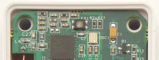
Click to zoom
Application Details
- Equipment Class
- TNB - Licensed Non-Broadcast Station Transmitter
- Date of Grant
- Apr 28, 2015
- Application Purpose
- Original Equipment
- Date of Application
- Apr 28, 2015
- Equipment Note
- Compact Transmitter
- Frequency Range
- 406.10000000 - 470.00000000
- Company
- Visiplex, Inc.
- Country
- United States
Documents & Files
Document Text
Text extracted from the exhibit documents filed with the FCC. Open a document above to read the original.
Users Manual
Version: 1.00 CT-15x Compact Transmitter - User Manual The CT-15x series of compact transmitters are designed to send pre-programmed alphanumeric messages or commands to compatible wireless receivers such as pagers, alphanumeric LED displays or other wireless controllers. When set to System Monitored mode, the CT-15x compact transmitters send a coded message to a receiver connected to a compatible monitoring system that analyzes the content of the coded message and initiates the respective action according to its internal programming. The CT-15x messages and alerts can be triggered using the push buttons, dry-contact closure, door magnet sensor, or horizontal position sensor. Each one of the triggers applicable to the device can be programmed with its own unique message or alert and activate one or multiple wireless receivers. Operation Note: The CT-15x compact transmitters are fully programmable using the VPS software. Please refer to the Software & Programming section below for more information. Follow these steps to activate the CT-15x compact transmitter: 1. Confirm that the CT-15x is programmed with the identical parameters of the wireless receiver (frequency, baud rate, message type, polarity, capcode, etc.). Note: use the VPS software to read the CT-15x parameters and modify them as required. 2. Activate the trigger/s applicable to your device (press a button, pull the cord, or press the cord push button). 3. Verify that the alphanumeric message is displayed on the respective receiver or that the receiver executed the wireless command (play pre-programmed tone stored in its memory, turn on strobe light, etc.). For system monitored devices, verify that the monitoring system received and processed the coded message. In addition to the messages and alerts generated by the device triggers, the device can also generate status and monitoring messages. These messages are listed below: 1. Cancel Alert: generated when the CT-15x is reset to normal status. Depending on the purchased device configuration, Cancel status occurs when a pull cord is pushed back to normal position, or when the cord push button is rapidly pressed 3 times). 2. Monitoring Alert: generated by the device when supervision, elevated alert, low battery or malfunction events occur. If Supervision and Elevated alerts are activated, their respective time interval is also user programmable. 3. Repeat: If activated, the original message is repeated as long as the CT-15x has not been reset to the Normal status. The number of repetitions and the time interval between each repetition is user programmable. Battery Replacement The CT-15x compact transmitters uses standard CR-2 lithium battery. Follow these steps to replace the battery: 1. Remove the 4 screws from the back cover and carefully separate the back cover from the wall plate. 2. Carefully remove the circuit board from the back cover while avoiding contact with the circuit board and antenna as much as possible. 3. Identify the installation polarity and direction of the installed battery. 4. Remove the old battery and install the new battery following the same polarity used by the old battery and according to the marking on the plastic case and circuit board (+ on battery should match the + on the CT-15x board). Warning: Incorrect polarity may cause permanent damage to the CT-15x and is not covered under warranty. If the device is not operational or the new battery feels hot to touch, remove the battery immediately. 5. Replace the back cover on the wall plate and use the 4 screws to secure them together. Hand tighten the screws to avoid damage to the case. Version: 1.00 Software & Programming The VPS software allows you to program the CT-15x messages and features using an optional USB cable (A Male to Mini B Male). Follow these steps to install the VPS software and USB drivers: Note: Do not connect the CT-15x to the PC at this point. 1. Log in to PC as a user with administrator privileges. 2. Download the VPS software (www.visiplex.com/docs/vps_setup.exe ) and save it to the PC desktop or Downloads folder. 3. Install the VPS software. 4. Install USB drivers applicable to the Windows OS (x86 or x64, i.e. 32-bit or 64-bit) from the shortcuts under the VPS program group under the Windows start menu. 5. Identify the COM number on the PC used for communication with the CT-15x: 5.1 Open Windows Device Manager and expand the Port (COM & LPT) section. Connect the CT-15x to the PC using the USB cable and note the COM number newly assigned to the installed device on Windows Device Manager. Windows may also display a system notification indicating the installed COM port in the notification area (next to the system clock). Note: If the COM number is higher than 16, you will need to re-assign a different COM port to this USB connection. Right click on the COM port, click on Properties - Port Settings - Advanced. Change the COM Port Number to a number between 4 and 16 and click OK (you may ignore any warning messages). 6. Run VPS software and allow it to auto-detect the connected device and serial (COM) port used. Note: If communication cannot be established or faster connection initialization is preferred, configure the VPS to use assigned COM port for communication with the device: 6.1 Click on the Settings menu. 6.2 Click on the Configuration & Settings menu item. 6.3 In the Serial Port drop down list, select the COM noted on step 5. 6.4 Clear the Auto Detect Connected Devices on Startup check box. 6.5 Click on Save. 7. If connection is successful, the VPS software information bar under the Settings menu will display the connection details and the CT-1xx programming screen will be displayed. Note: If the programming screen is not displayed, click on the Wireless Devices toolbar menu and then click on CT- 1xx Compact Transmitter Programmer. 8. Click on Read to read the CT-15x parameters. For more information and details regarding each field and feature, press F1 on your keyboard or cl…
Text truncated - open the document above for the full version.
External Photos
CT15X – External Photos CT‐151 ‐ Front View CT‐152 ‐ Front View CT‐154 ‐ Front View CT‐155 ‐ Front View CT‐156 ‐ Front View CT‐151, CT‐152, CT‐154, CT‐155, CT‐156 ‐ Rear View
ID Label/Location Info
CT15X – Label Artwork & Placement Figure 1 ‐ Artwork Figure 2 ‐ Placement Note : Label model is from the Zebra ultimate series that uses permanent adhesive.
Internal Photos
CT15X – Internal Photos CT‐151 ‐ Front View CT‐152 & CT‐154 ‐ Front View CT‐155 ‐ Front View CT‐156 ‐ Front View CT‐151, CT‐152, CT‐154, CT‐155, CT‐156 ‐ Rear View
RF Exposure Info
EMC Test Data Client: Contact: Standard: Test Specific Details General Test Configuration Yes Device complies with SAR exclusion at 5 mm separation: Test Engineer: M. Birgani Calculation uses the free space transmission formula: S = (PG)/(4 πd 2 ) Where: S is power density (W/m 2 ), P is output power (W), G is antenna gain relative to isotropic, d is separation distance from the transmitting antenna (m). Summary of Results Maximum Permissible Exposure Objective: The objective of this test session is to perform final qualification testing of the EUT with respect to the specification listed above. Date of Test: 4/6/2015 Ben AgamProject Coordinator: - FCC Part 90.217Class: N/A Visiplex Inc.Job Number: J97803 Model: CT-151, CT-152, CT-154, CT-155 and CT-156 T-Log Number: T97845 Project Manager: Deepa Shetty SAR Exclusion Calculation Cable Loss AntPower Freq.LossGainat AntEIRP MHzdBmmW*dBdBidBmmW 4706.04.006.05.00.553.0 SAR Exclusion Limit Power EUTSeparation Distance (mm) SAR Exclusion Calc. T97845 Visiplex.xlsSAR Ex. CalcPage 1 of 1
Test Report
Radio Test Report FCC Part 90 (406.1 MHz to 470 MHz) Models: CT-151, CT-152, CT-154, CT-155 and CT-156 COMPANY: Visiplex Inc. 1287 Barclay Blvd Buffalo, IL 60089 TEST SITE(S): National Technical Systems - Silicon Valley 41039 Boyce Road. Fremont, CA. 94538-2435 REPORT DATE: April 14, 2015 REISSUE DATE: April 21, 2015 FINAL TEST DATES: April 6, 2015 TOTAL NUMBER OF PAGES: 24 PROGRAM MGR / QUALITY ASSURANCE DELEGATE / TECHNICAL REVIEWER: FINAL REPORT PREPARER: ______________________________ ______________________________ David W. Bare David Guidotti Chief Engineer Senior Technical Writer National Technical Systems - Silicon Valley is accredited by the A2LA, certificate number 0214.26, to perform the test(s) listed in this report, except where noted otherwise. This report and the information contained herein represent the results of testing test articles identified and selected by the client performed to specifications and/or procedures selected by the client. National Technical Systems (NTS) makes no representations, expressed or implied, that such testing is adequate (or inadequate) to demonstrate efficiency, performance, reliability, or any other characteristic of the articles being tested, or similar products. This report should not be relied upon as an endorsement or certification by NTS of the equipment tested, nor does it represent any statement whatsoever as to its merchantability or fitness of the test article, or similar products, for a particular purpose. This report shall not be reproduced except in full File: R97973 Rev 1 Page 1 National Technical Systems - Silicon Valley Project number J97803 Report Date: April 14, 2015 Reissue Date: April 21, 2015 REVISION HISTORY Rev# Date Comments Modified By - April 14, 2015 First release 1 April 21, 2015 Revised to update a note in the test log concerning the mask which appeared on Page 18. David Guidotti Test Report R97973 Rev 1 Page 2 National Technical Systems - Silicon Valley Project number J97803 Report Date: April 14, 2015 Reissue Date: April 21, 2015 TABLE OF CONTENTS REVISION HISTORY ................................................................................................................................................ 2 TABLE OF CONTENTS ............................................................................................................................................ 3 SCOPE .......................................................................................................................................................................... 4 OBJECTIVE ................................................................................................................................................................ 5 STATEMENT OF COMPLIANCE ........................................................................................................................... 5 DEVIATIONS FROM THE STANDARDS .............................................................................................................. 5 TEST RESULTS .......................................................................................................................................................... 6 FCC PART 90 AND RSS-119 .................................................................................................................................... 6 EXTREME CONDITIONS ...................................................................................................................................... 7 MEASUREMENT UNCERTAINTIES .................................................................................................................... 7 EQUIPMENT UNDER TEST (EUT) DETAILS ...................................................................................................... 8 GENERAL ................................................................................................................................................................ 8 OTHER EUT DETAILS ........................................................................................................................................... 8 ENCLOSURE ........................................................................................................................................................... 8 MODIFICATIONS ................................................................................................................................................... 8 SUPPORT EQUIPMENT ......................................................................................................................................... 8 EUT INTERFACE PORTS ...................................................................................................................................... 9 EUT OPERATION ................................................................................................................................................... 9 TESTING ................................................................................................................................................................... 10 GENERAL INFORMATION ................................................................................................................................. 10 RF PORT MEASUREMENT PROCEDURES ...................................................................................................... 10 OUTPUT POWER .................................................................................................................................................. 10 BANDWIDTH MEASUREMENTS ...................................................................................................................... 11 CONDUCTED SPURIOUS EMISSIONS .............................................................................................................. 11 TRANSMITTER MASK MEASUREMENTS ....................................................................................................... 11 FREQU…
Text truncated - open the document above for the full version.
Test Setup Photos
Test Configuration Photographs
Contact Information
Applicant
Sam A Agam(VP of Engineering)
Technical Contact
National Technical Systems - Silicon ValleyDavid Bare
[email protected]5105783500
41039 Boyce Road · Fremont, California · United States
Test Firm
Element Materials Technology Fremont NewarkDavid Bare
Technical Specifications
| # | Rule Parts | Frequency Range | Power Output | Emission | Tolerance |
|---|---|---|---|---|---|
| 1 | 90.217(b) | 406.1 MHz - 470 MHz | 4.00 mW | 7K10F1D | 1800.0000000000 Hz |