2AAFY6099B1750Wireless Mixing Valve
Fluid Handling LLC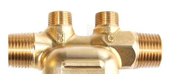
Click to zoom
Application Details
- Equipment Class
- DXT - Part 15 Low Power Transceiver, Rx Verified
- Date of Grant
- Nov 26, 2013
- Application Purpose
- Original Equipment
- Date of Application
- Nov 26, 2013
- Equipment Note
- Wireless Mixing Valve
- Frequency Range
- 915.00000000 - 915.00000000
- Company
- Fluid Handling LLC
- Country
- United States
Documents & Files
Document Text
Text extracted from the exhibit documents filed with the FCC. Open a document above to read the original.
Users Manual
Instruction Manual Laing Thermotech ACT-4 wireless Potable Hot Water Recirculation Kit Table of Contents Introduction and Safety................................................................................................ 2 Introduction............................................................................................................... 2 Safety.......................................................................................................................... 2 Safety terminology and symbols........................................................................ 2 User safety............................................................................................................. 3 Environmental safety............................................................................................4 Product Description...................................................................................................... 6 General description.................................................................................................. 6 Operational specifications....................................................................................... 6 Installation...................................................................................................................... 9 Preinstallation............................................................................................................ 9 Recommended installation....................................................................................10 Install the pump...................................................................................................... 11 Install the valve........................................................................................................ 12 Commissioning, Startup, Operation, and Shutdown............................................. 15 Thermostat controlled operation..........................................................................15 Thermostat controlled operation Plus Timer...................................................... 15 Optional Push-Button / Signal Repeater..............................................................17 Maintenance................................................................................................................ 19 Valve and pump inspection................................................................................... 19 Pairing after pump or valve replacement............................................................ 19 Replace the batteries..............................................................................................19 Return to service after shutdown of two weeks or more................................... 20 Troubleshooting.......................................................................................................... 21 LED codes................................................................................................................ 21 Operation troubleshooting................................................................................... 21 Table of Contents Laing Thermotech ACT-4 wireless Potable Hot Water Recirculation Kit Instruction Manual 1 Introduction and Safety Introduction Purpose of this manual The purpose of this manual is to provide necessary information for: • Installation • Operation • Maintenance CAUTION: Read this manual carefully before installing and using the product. Improper use of the product can cause personal injury and damage to property, and may void the warranty. NOTICE: Save this manual for future reference, and keep it readily available at the location of the unit. Safety WARNING: • The operator must be aware of safety precautions to prevent physical injury. • Any pressure-containing device can explode, rupture, or discharge its contents if it is over-pressurized. Take all necessary measures to avoid over-pressurization. • Operating, installing, or maintaining the unit in any way that is not covered in this manual could cause death, serious personal injury, or damage to the equipment. This includes any modification to the equipment or use of parts not provided by Xylem. If there is a question regarding the intended use of the equipment, please contact a Xylem representative before proceeding. • Do not change the service application without the approval of an authorized Xylem representative. CAUTION: You must observe the instructions contained in this manual. Failure to do so could result in physical injury, damage, or delays. Safety terminology and symbols About safety messages It is extremely important that you read, understand, and follow the safety messages and regulations carefully before handling the product. They are published to help prevent these hazards: • Personal accidents and health problems • Damage to the product • Product malfunction Introduction and Safety 2Laing Thermotech ACT-4 wireless Potable Hot Water Recirculation Kit Instruction Manual Hazard levels Hazard levelIndication DANGER: A hazardous situation which, if not avoided, will result in death or serious injury WARNING: A hazardous situation which, if not avoided, could result in death or serious injury CAUTION: A hazardous situation which, if not avoided, could result in minor or moderate injury NOTICE: • A potential situation which, if not avoided, could result in undesirable conditions • A practice not related to personal injury Hazard categories Hazard categories can either fall under hazard levels or let specific symbols replace the ordinary hazard level symbols. Electrical hazards are indicated by the following specific symbol: Electrical Hazard: These are examples of other categories that can occur. They fall under the ordinary hazard levels and may use complementing symbols: • Crush hazard • Cutting hazard • Arc flash hazard User safety General safety rules These safety rules apply: • Always keep the work area clean. • Pay attention to the risks prese…
Text truncated - open the document above for the full version.
External Photos
For valve: label is located on back of device.
Test Report
NVLAP Lab code: 100414-0 FCC 47 CFR PART 15 SUBPART C INDUSTRY CANADA RSS-210 ISSUE 8 CERTIFICATION TEST REPORT FOR Wireless Mixing Valve MODEL NUMBER: 6099B1750, 6099E1600 FCC ID: 2AAFY6099B1750 IC: 11144A-6099B1750 REPORT NUMBER: 10005005C ISSUE DATE: September 23, 2013 Prepared for Fluid Handling LLC 8200 N Austin Ave Morton Grove, IL 60053 Prepared by UL LLC 333 Pfingsten Rd. Northbrook, IL 60062 TEL: (847) 272-8800 REPORT NO: 10005005C DATE: September 23, 2013 FCC ID: 2AAFY6099B1750 IC: 11144A-6099B1750 Page 2 of 22 UL LLC FORM NO: CCSUP4701G 333 Pfingsten Rd., Northbrook, IL 60062 TEL: (847) 272-8800 This report shall not be reproduced except in full, without the written approval of UL LLC. Revision History Rev. Issue Date Revisions Revised By -- 09/23/13 Initial Issue M.Ferrer REPORT NO: 10005005C DATE: September 23, 2013 FCC ID: 2AAFY6099B1750 IC: 11144A-6099B1750 Page 3 of 22 UL LLC FORM NO: CCSUP4701G 333 Pfingsten Rd., Northbrook, IL 60062 TEL: (847) 272-8800 This report shall not be reproduced except in full, without the written approval of UL LLC. TABLE OF CONTENTS 1. ATTESTATION OF TEST RESULTS ............................................................................................. 4 2. TEST METHODOLOGY .................................................................................................................. 5 3. FACILITIES AND ACCREDITATION .......................................................................................... 5 4. CALIBRATION AND UNCERTAINTY .......................................................................................... 5 4.1. MEASURING INSTRUMENT CALIBRATION ............................................................................. 5 4.2. SAMPLE CALCULATION ............................................................................................................ 5 4.3. MEASUREMENT UNCERTAINTY ............................................................................................... 5 5.5. DESCRIPTION OF TEST SETUP ................................................................................................ 7 6. TEST AND MEASUREMENT EQUIPMENT ................................................................................ 9 7. TEST RESULTS ............................................................................................................................... 10 7.1.1. 99%, 20dB BANDWIDTH ................................................................................................. 10 7.2. RADIATED EMISSIONS............................................................................................................. 13 7.2.1. HARMONICS AND SPURIOUS EMISSIONS ABOVE 1GHz ....................................... 16 7.2.2. WORST-CASE BELOW 1 GHz ........................................................................................ 18 8. SETUP PHOTOS .............................................................................................................................. 20 REPORT NO: 10005005C DATE: September 23, 2013 FCC ID: 2AAFY6099B1750 IC: 11144A-6099B1750 Page 4 of 22 UL LLC FORM NO: CCSUP4701G 333 Pfingsten Rd., Northbrook, IL 60062 TEL: (847) 272-8800 This report shall not be reproduced except in full, without the written approval of UL LLC. 1. ATTESTATION OF TEST RESULTS COMPANY NAME: Fluid Handling 8200 N Austin Morton Grove, IL 60053 EUT DESCRIPTION: Wireless Mixing Valve MODEL: 6099B1750, 6099E1600 SERIAL NUMBER: 6 DATE TESTED: September 3, 2013 – September 13, 2013 APPLICABLE STANDARDS STANDARD TEST RESULTS CFR 47 Part 15 Subpart C Part 15.249 Pass INDUSTRY CANADA RSS-210 Issue 8 Annex A2.9 Pass INDUSTRY CANADA RSS-GEN Issue 3 Pass UL Verification Services Inc. tested the above equipment in accordance with the requirements set forth in the above standards. All indications of Pass/Fail in this report are opinions expressed by UL Verification Services Inc. based on interpretations and/or observations of test results. Measurement Uncertainties were not taken into account and are published for informational purposes only. The test results show that the equipment tested is capable of demonstrating compliance with the requirements as documented in this report. Note: The results documented in this report apply only to the tested sample, under the conditions and modes of operation as described herein. This document may not be altered or revised in any way unless done so by UL Verification Services Inc. and all revisions are duly noted in the revisions section. Any alteration of this document not carried out byUL Verification Services Inc. will constitute fraud and shall nullify the document. This report must not be used by the client to claim product certification, approval, or endorsement by NVLAP, NIST, any agency of the Federal Government, or any agency of any government. Approved & Released For UL CCS By: Tested By: BART MUCHA MICHAEL FERRER WiSE STAFF ENGINEER WiSE Project Lead UL Verification Services Inc. UL Verification Services Inc. REPORT NO: 10005005C DATE: September 23, 2013 FCC ID: 2AAFY6099B1750 IC: 11144A-6099B1750 Page 5 of 22 UL LLC FORM NO: CCSUP4701G 333 Pfingsten Rd., Northbrook, IL 60062 TEL: (847) 272-8800 This report shall not be reproduced except in full, without the written approval of UL LLC. 2. TEST METHODOLOGY The tests documented in this report were performed in accordance with ANSI C63.4-2003, FCC CFR 47 Part 15, RSS-GEN Issue 3, and RSS-210 Issue 8. 3. FACILITIES AND ACCREDITATION The test sites and measurement facilities used to collect data are located at 333 Pfingsten Road, Northbrook, IL 60062, USA. UL NBK is accredited by NVLAP, Laboratory Code 100414-0. 4. CALIBRATION AND UNCERTAINTY 4.1. MEASURING INSTRUMENT CALIBRATION The measuring equipment utilized to perform the tests documented in this report has been calibrated in accordance with the manufacturer's recommendations, and is traceable to recognized national standards. 4.2. SAMPLE CALCULATION Where relevant, the…
Text truncated - open the document above for the full version.
Test Setup Photos
REPORT NO: 10005005C DATE: September 23, 2013 FCC ID: 2AAFY6099B1750 IC: 11144A-6099B1750 Page 20 of 22 UL LLC FORM NO: CCSUP4701G 333 Pfingsten Rd., Northbrook, IL 60062 TEL: (847) 272-8800 This report shall not be reproduced except in full, without the written approval of UL LLC. 8. SETUP PHOTOS RADIATED RF MEASUREMENT SETUP (BELOW 1 GHz) RADIATED FRONT PHOTO (BELOW 1 GHz) REPORT NO: 10005005C DATE: September 23, 2013 FCC ID: 2AAFY6099B1750 IC: 11144A-6099B1750 Page 21 of 22 UL LLC FORM NO: CCSUP4701G 333 Pfingsten Rd., Northbrook, IL 60062 TEL: (847) 272-8800 This report shall not be reproduced except in full, without the written approval of UL LLC. RADIATED RF MEASUREMENT SETUP (ABOVE 1 GHz) RADIATED FRONT PHOTO (ABOVE 1 GHz) REPORT NO: 10005005C DATE: September 23, 2013 FCC ID: 2AAFY6099B1750 IC: 11144A-6099B1750 Page 22 of 22 UL LLC FORM NO: CCSUP4701G 333 Pfingsten Rd., Northbrook, IL 60062 TEL: (847) 272-8800 This report shall not be reproduced except in full, without the written approval of UL LLC. RADIATED RF MEASUREMENT SETUP FOR PORTABLE CONFIGURATION END OF REPORT X-AXIS FRONT PHOTO
Contact Information
Applicant
Stanley P Evans(Sr. Design Engineer)
Test Firm
UL LLCRick Titus
Technical Specifications
| # | Rule Parts | Frequency Range | Power Output |
|---|---|---|---|
| 1 | 15C | 915 MHz - 915 MHz | - |
Other Applications from Fluid Handling LLC
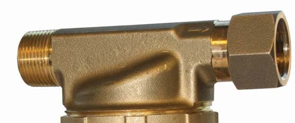
2AAFY6050B4150
Nov 20, 2013Wireless Pump
Equipment Class
DXX - Part 15 Low Power Communication Device Transmitter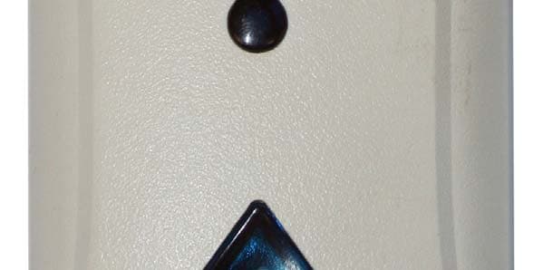
2AAFY6099B1500
Nov 06, 2013Wireless Push Button
Equipment Class
DXX - Part 15 Low Power Communication Device Transmitter