2AAH5GSMK4Geoscope Mk4
Kontur US, Inc.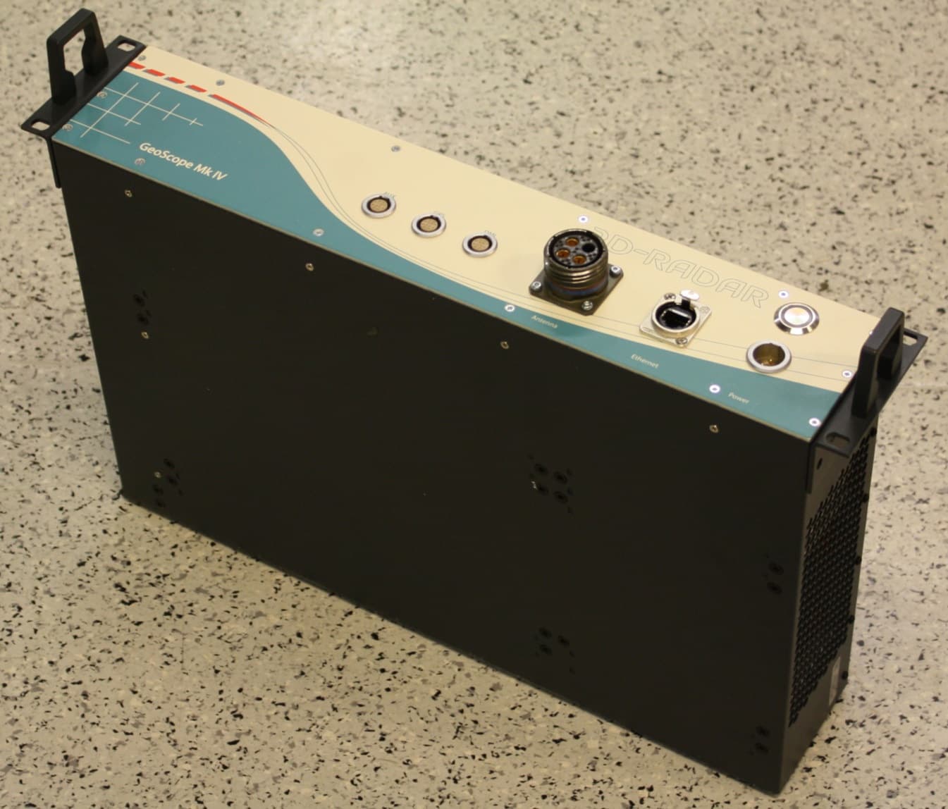
Click to zoom
Application Details
- Equipment Class
- UWB - Ultra Wideband Transmitter
- Date of Grant
- Aug 07, 2013
- Application Purpose
- Original Equipment
- Date of Application
- Jul 07, 2013
- Equipment Note
- Geoscope Mk4
- Frequency Range
- 140.00000000 - 3000.00000000
- Company
- Kontur US, Inc.
- Country
- United States
Documents & Files
Document Text
Text extracted from the exhibit documents filed with the FCC. Open a document above to read the original.
Users Manual
3d-radar as GeoScope™ User’s Manual Model Geoscope Mk4 Document Version 2.0 3d-radar as 3d-radar as GeoScope TM User’s Manual © 2013 3d-Radar AS Page I Revision 2.0 Date: 02/07/2013 Contact Details 3d-Radar AS Klæbuveien 196B NO-7037 Trondheim, Norway (+47) 7289 3200 Phone (+47) 7289 3201 Fax www.3d-radar.com Copyright and Trademarks © 2002-2013, 3d-Radar AS. All rights reserved. 3d-Radar, GeoScope TM is a trademark of 3d- Radar AS. Microsoft, Windows, and Windows XP are either registered trademarks or trademarks of Microsoft Corporation in the United States and/or other countries. All other trademarks are the property of their respective owners. Release Notice This is the March 2013 release of the GeoScope User’s Manual. It applies to the GeoScope Mk4 radar. The following limited warranties give you specific legal rights. Hardware Limited Warranty 3d-Radar warrants that this 3d-Radar hardware product (the“Product”) shall be free from defects in materials and workmanship and will substantially conform to 3d-Radar’s applicable published specifications for the Product for a period of one (1) year, starting from the date of delivery. The warranty set forth in this paragraph shall not apply to software/firmware products. User Software and Firmware License, Limited Warranty This 3d-Radar User Software and/or Firmware product (the “Software”) is licensed and not sold. Its use is governed by the provisions of the applicable End User License Agreement (“EULA”), if any, included with the Software. In the absence of a separate EULA included with the Software providing different limited warranty terms, exclusions, and limitations, the following terms and conditions shall apply. 3d-Radar warrants that this 3d-Radar Software product will substantially conform to 3d-Radar’s applicable published specifications for the Software for a period of ninety (90) days, starting from the date of delivery. Warranty Remedies 3d-Radar's sole liability and your exclusive remedy under the warranties set forth above shall be, at 3d-Radar’s option, to repair or replace any Product or Software that fails to conform to such warranty (“Nonconforming Product”), or refund the purchase price paid by you for any such Nonconforming Product, upon your return of any Nonconforming Product to 3d- Radar in accordance with 3d-Radar’s standard return material authorization procedures. Warranty Exclusions and Disclaimer These warranties shall be applied only in the event and to the extent that: (i) the Products and Software are properly and correctly installed, configured, interfaced, maintained, stored, and operated in accordance with 3d- Radar’s relevant operator's manual and specifications, and; (ii) the Products and Software are not modified or misused. The preceding warranties shall not apply to, and 3d- Radar shall not be responsible for defects or performance problems resulting from (i) the combination or utilization of the Product or Software with products, information, data, systems or devices not made, supplied or specified by 3d-Radar; (ii) the operation of the Product or Software under any specification other than, or in addition to, 3d-Radar's standard specifications for its products; (iii) the unauthorized modification or use of the Product or Software; (iv) damage caused by accident, lightning or other electrical discharge, fresh or salt water immersion or spray; or (v) normal wear and tear on consumable parts (e.g., batteries). THE WARRANTIES ABOVE STATE 3D-RADAR'S ENTIRE LIABILITY, AND YOUR EXCLUSIVE REMEDIES, RELATING TO PERFORMANCE OF THE PRODUCTS AND SOFTWARE. EXCEPT AS OTHERWISE EXPRESSLY PROVIDED HEREIN, THE PRODUCTS, SOFTWARE, AND ACCOMPANYING DOCUMENTATION AND MATERIALS ARE PROVIDED “ASIS” AND WITHOUT EXPRESS OR IMPLIED WARRANTY OF ANY KIND BY EITHER 3D-RADAR AS OR ANYONE WHO HAS BEEN INVOLVED IN ITS CREATION, PRODUCTION, INSTALLATION, OR DISTRIBUTION, INCLUDING, BUT NOT LIMITED TO, THE IMPLIED WARRANTIES OF MERCHANTABILITY AND FITNESS FOR A PARTICULAR PURPOSE, TITLE, AND NONINFRINGEMENT. THE STATED EXPRESS WARRANTIES ARE IN LIEU OF ALL OBLIGATIONS OR LIABILITIES ON THE PART OF 3D-RADAR ARISING OUT OF, OR IN CONNECTION WITH, ANY PRODUCTS OR SOFTWARE. SOME STATES AND JURISDICTIONS DO NOT ALLOW LIMITATIONS ON DURATION OR THE EXCLUSION OF AN IMPLIED WARRANTY, SO THE ABOVE LIMITATION MAY NOT APPLY TO YOU. Limitation of Liability 3D-RADAR’S ENTIRE LIABILITY UNDER ANY PROVISION HEREIN SHALL BE LIMITED TO THE GREATER OF THE AMOUNT PAID BY YOU FOR THE PRODUCT OR SOFTWARE LICENSE. TO THE MAXIMUM EXTENT PERMITTED BY APPLICABLE LAW, IN NO EVENT SHALL 3D-RADAR OR ITS SUPPLIERS BE LIABLE FOR ANY INDIRECT, SPECIAL, INCIDENTAL, OR CONSEQUENTIAL DAMAGES WHATSOEVER UNDER ANY CIRCUMSTANCE OR LEGAL THEORY RELATING IN ANY WAY TO THE PRODUCTS, SOFTWARE, AND ACCOMPANYING DOCUMENTATION AND MATERIALS, (INCLUDING, WITHOUT LIMITATION, DAMAGES FOR LOSS OF BUSINESS PROFITS, BUSINESS INTERRUPTION, LOSS OF BUSINESS INFORMATION, OR ANY OTHER PECUNIARY LOSS), REGARDLESS OF WHETHER 3D-RADAR HAS BEEN ADVISED OF THE POSSIBILITY OF ANY SUCH LOSS AND REGARDLESS OF THE COURSE OF DEALING WHICH DEVELOPS OR HAS DEVELOPED BETWEEN YOU AND 3D-RADAR. BECAUSE SOME STATES AND JURISDICTIONS DO NOT ALLOW THE EXCLUSION OR LIMITATION OF LIABILITY FOR CONSEQUENTIAL OR INCIDENTAL 3d-radar as GeoScope TM User’s Manual © 2013 3d-Radar AS Page II Revision 2.0 Date: 02/07/2013 DAMAGES, THE ABOVE LIMITATION MAY NOT APPLY TO YOU. Regulations and Safety The GeoScope Ground Penetrating Radar comprises a radar transmitter and receiver. Regulations regarding the use of the radars vary greatly from country to country. In some countries, the unit can be used without obtaining an end-user license. Other countries require end-user licensing. Consult your local communications governing agency for licensing information. Before operating this radar, determine if authorization or a license to operate the unit is required in your country. It is the responsibility of the end user to…
Text truncated - open the document above for the full version.
Cover Letter(s)
Federal Communications CommissionDA 12-41 Before the Federal Communications Commission Washington, D.C. 20554 In the matter of Curtiss-Wright Controls Inc. Request for Waiver of Part 15 of the Commission’s Rules Applicable to Ultra- Wideband Devices ) ) ) ) ) ) ) ) ) ET Docket No. 10-167 ORDER Adopted: January 11, 2012Released: January 11, 2012 By the Chief, Office of Engineering and Technology: I.INTRODUCTION 1.By this Order, we grant a request by Curtiss-Wright Controls Inc. (“CWCI”), to waive Sections 15.503(d) and 15.521(d) of our ultra-wideband (“UWB”) rules for its ground penetrating radar (“GPR”) system, known as 3d-Radar. 1 GPR devices are field disturbance sensors that detect buried objects, changes in material, and cracks in ground or in other subsurface structures and are typically used in the maintenance of highways and bridge infrastructures in the United States. GPR devices achieve these objectives by utilizing a very wide operational bandwidth that spans frequency bands used by a broad array of radio services. 2.Specifically, we are waiving the definitional requirement in Section 15.503(d), which specifies the minimum operational bandwidth of an UWB transmitter, and the UWB measurement procedure in Section 15.521(d). This action will permit CWCI to manufacture and market the 3d-Radar device upon receiving FCC equipment authorization. We also will require CWCI to comply with all other technical and operational requirements for unlicensed UWB GPR devices in Section 15.509. We find that granting this waiver request is in the public interest because it will make available a product that will improve the safety of our nation’s transportation infrastructure without increasing the potential for interference to authorized radio services. II.BACKGROUND 3.On February 14,2002, the Commission adopted regulations to permit the operation of UWB transmitters. 2 Categories of UWB devices that can be marketed and operated on an unlicensed 1 See “Curtiss-Wright Controls Inc., Request for Waiver of Part 15 of the Commission’s Rules Applicable to Ultra- Wideband Devices” (CWCI Waiver Request), filed June 10, 2010, ET Docket No. 10-167; see also47 C.F.R §§15.503(d) and 15.521(d). 2 See First Report and Order(“1 st R&O”) in ET Docket No. 98-153, 17 FCC Rcd 7435 (2002); Erratumin ET Docket No. 98-153, 17 FCC Rcd 10505 (2002); Memorandum Opinion and Order and Further Notice of Proposed Rule Makingin ET Docket No. 98-153, 18 FCC Rcd 3857 (2003); and Second Report and Order and Second (continued....) Federal Communications CommissionDA 12-41 2 basis under the Part 15 regulations include imaging systems, vehicular radars, and indoor communications systems. 3 These transmitters operate using spectrum that is allocated to various radio services, including frequency bands that are allocated to both Federal and to non-Federal operations. 4 They also operate in several restricted frequency bands within which the operation of other types of Part 15 transmitters are prohibited. 5 No spectrum is allocated to UWB devices, which share these frequency bands with authorized radio services on a sufferance basis and may not cause harmful interference to authorized radio services. 6 4.Unlicensed UWB GPR devices are governed by Part 15, Subpart F of the Commission’s rules. Section 15.503(d) specifies a minimal operational bandwidth in defining an UWB transmitter, i.e., a fractional bandwidth equal to or greater than 0.20 or an UWB bandwidth equal to or greater than 500 megahertz, regardless of the fractional bandwidth. 7 UWB devices typically employ pulse modulation technologies whereby very short bursts of energy are modulated and emitted to convey information, producing emission bandwidths often exceeding one gigahertz. 8 When it adopted the UWB rules, the Commission stated that UWB devices could use other modulation types if they meet the minimum bandwidth requirements and that this requirement was intended to avoid having devices designed for the restricted bands if they did not need to operate in those bands. 9 The Commission further stated that “it was unlikely” that swept frequency, stepped frequency, or frequency hopping systems would comply with the minimum bandwidth requirement because, unlike UWB systems, the emissions for these other systems were typically measured with the sweep/step/hopping function stopped. 10 Section 15.521(d) of the Commission’s rules sets forth the measurement procedures for UWB devices to demonstrate compliance with applicable emission limits. For emissions above 960 MHz, this rule requires that, if pulse gating is used and the transmitter is quiescent for longer intervals than the nominal pulse repetition interval, measurements are made with the pulse train gated on; also, the Commission may consider alternate measurement procedures. 11 5.On June 10, 2010, Curtiss-Wright Controls, Inc. (“CWCI”) filed a request for a waiver of the UWB minimum bandwidth requirement in Section15.503(d) and the UWB measurement procedures in Section 15.521(d) of the Commission’s rules to permit the marketing and operation of its stepped frequency GPR system known as 3d-Radar. CWCI states that its 3d-Radar system operates between 140 MHz and 3 GHz using stepped frequency modulation to achieve superior performance characteristics of deep signal penetration, high resolution imaging, and fast survey speeds. CWCI states that to achieve (...continued from previous page) Memorandum Opinion and Order(“2 nd R&O”) in ET Docket No. 98-153, 19 FCC Rcd 24525 (2004). See also47 C.F.R. §§ 15.501-15.525. 3 Imaging systems consist of GPRs, wall imaging systems, through-wall imaging systems, surveillance systems, and medical imaging systems. 4 The operation of Federal radio stations is regulated by the National Telecommunications and Information Administration (“NTIA”), while operation of stations by commercial entities, state and local governments, and the general public is regulated by the Commission. 5 47 C.F.R. § …
Text truncated - open the document above for the full version.
External Photos
3d-Radar Geoscope front view 3d-Radar Geoscope rear view 3d-Radar Geoscope bottom view
External Photos
3d-Radar DX2125 antenna 3d-Radar Interior antenna electronics (antenna panels equipped with Antenna Front end and MUX prior to final assembly inside mechanical stru cture)
ID Label/Location Info
2013 44040 Geoscope Mk4 FCC ID:2AAH5GSMK4 This device complies with part 15 of the FCC Rules. Operation is subject to the following two conditions: (1) This device may not cause harmful interference, and (2) this device must accept any interference received, including interference that may cause undesired operation.
Internal Photos
3d-Radar Geoscope cPCI computer Top View 3d-Radar Geoscope cPCI computer Bottom View 3d-Radar Geoscope Breakout Board Top View 3d-Radar Geoscope Breakout Board Bottom View
Internal Photos
3d-Radar Geoscope Chassis without front panel. 3d-Radar Geoscope Transmitter board. Top view. Shie ld removed. 3d-Radar Geoscope Transmitter board. Top view. Shie lded. 3d-Radar Geoscope Transmitter board. Bottom view 3d-Radar Geoscope Dual-Channel Receiver board. Top view. Shield removed. 3d-Radar Geoscope Transmitter board. Top view. Shie lded. 3d-Radar Geoscope Dual-Channel Receiver board. Bott om view
Internal Photos
3d-Radar Geoscope Antenna Front End ModuleThis is a RF-board with no components on the bottom side (ground plane only) 3d-Radar Geoscope RF-multiplexer This is a RF-board with no components on the bottom side (ground plane only)
Test Report
Saab AB(publ) Support and Services Postal address Box 360 SE-831 25 Östersund Sweden Visiting address Storlienvägen 56 Telephone +46 63 15 60 00 Telefax +46 63 15 61 99 Registered office Linköping Registered No 556036-0793 VAT No SE556036079301 www.saabgroup.com We are represented in Arboga, Göteborg, Lidköping, Linköping, Ljungbyhed, Norrtälje, Nyköping, Stockholm, Uppsala, Växjö, Åryd, Örebro, Östersund Överföring av dokument i elektronisk form Detta dokument är en elektronisk kopia. Vid konvertering eller överföring i elektronisk form kan dokumentet bli förvanskat. Det fastställda pappersoriginalet är det gällande dokumentet. Transfer of document in electronic form This document is an electronic copy of the original. When converting or transferring the document into electronic form, it could be distorted. The original paper document is to be considered the valid document. This report may not be reproduced other than in full, except with the prior written approval of the issuing laboratory. Saab AB (publ.), Support and Services Box 360. SE-831 25 Östersund, Sweden. Visitors: Storlienvägen 56. Telephone: +46 63 15 61 00. Telefax: +46 63 15 61 99 Internal Ref No 21519-01000 Template rev. 2010-10-11 Distribution 3D-Radar AS Klæbuveien 196B 7037 Trondheim Norge Copy OFLV archive Document Test Report Date May 14, 2013 Prepared OFLBIA, Björn Olsson Senior EMC engineer Ref. No EMC-Osd-13-0283-01 Supersedes Page 1(31) Title EMC test of GeoScope Mk 4 radar with antenna DX1821 Summary: The object of the test is to show compliance with the emission requirements of Federal Communications Commission (FCC) Part 15 Subpart F and Industry Canada (IC) RSS-220 for ground penetrating radars (GPR) using ultra wideband (UWB) technology. The EUT complied with the requirement of radiated emissions given in FCC Part 15 Subpart F and IC RSS-220, measured in the frequency range 30 MHz – 18 GHz. The EUT also fulfilled the requirements of frequency notching and frequency step parameters in the FCC Waiver DA 12-41, dated January 11, 2012. The tests have been performed at an Open Area Test Site (OATS). The test site is registered at FCC with the registration number 389317 and at IC with the site number 4660C-1. Approved: [The original is signed] Lennart Hamberg Technical Manager Ref No EMC-Osd-13-0283-01 Page 2(31) Contents 1 General information ................................................................................................. 3 2 Test methods and results .......................................................................................... 4 2.1 Results ......................................................................................................... 4 2.2 Applicable documents .................................................................................. 4 3 Equipment under test (EUT)..................................................................................... 5 3.1 Identification of equipment under test .......................................................... 5 3.2 General configuration of the EUT ................................................................ 6 3.3 Operation of EUT during tests ...................................................................... 7 4 Test site.................................................................................................................... 8 4.1 Description................................................................................................... 8 4.2 Ambient signals ........................................................................................... 8 5 Results ..................................................................................................................... 9 5.1 Measurement of radiated emission, 30 MHz – 960 MHz .............................. 9 5.2 Measurement of radiated emission, 960 MHz – 18 GHz ............................. 14 5.3 Measurement of UWB bandwidth and peak emissions ............................... 24 Ref No EMC-Osd-13-0283-01 Page 3(31) 1 General information Date of test: April 22 and 23, 2013 Location of the test: Saab AB Storlienvägen 56 SE-831 52 Östersund Sweden Test performed by: Björn Olsson, Saab AB Client: 3D-Radar AS Klæbuveien 196B 7037 Trondheim Norway Client’s observer: Egil Eide, 3D-Radar AS Ref No EMC-Osd-13-0283-01 Page 4(31) 2 Test methods and results 2.1 Results The test results in this report apply only for the tested EUT. EMISSION REQUIREMENTS ACCORDING TO FCC Part 15 Subpart F and IC RSS-220 Environmental phenomena Test method Requirement Result Comments Radiated emission 30 MHz – 960 MHz ANSI C63.4 FCC 15.209 IC RSS-220, section 3.4 PASS Radiated emission 960 MHz – 18 GHz FCC 02-48 IC RSS-220 FCC 15.509 (d) IC RSS-220, section 6.2.1(d) PASS Radiated emission 1164 MHz – 1240 MHz 1559 MHz – 1610 MHz FCC 02-48 IC RSS-220 FCC 15.509 (e) IC RSS-220, section 6.2.1(e) PASS UWB definition FCC 15.503 (a) 15.509(a) IC RSS-220, section 6.2.1(a) PASS f M : f L : f H : f C : 770.8 MHz 286.8 MHz 1583 MHz 934.9 MHz Peak emission at f M FCC 02-48 IC RSS-220 FCC 15.509 (f) IC RSS-220, section 6.2.1(g) PASS 2.2 Applicable documents ANSI C63.4 15 September, 2009 American National Standard for Methods of Measurement of Radio-Noise Emissions from Low-Voltage Electrical and Electronic Equipment in the range of 9 kHz to 40 GHz FCC CFR 47 Part 15 20 April, 2013 Radio Frequency Devices FCC 02-48 22 April, 2002 Revision of Part 15 of the Commission’s Rules Regarding Ultra-Wideband Transmission Systems DA 12-41 11 January, 2012 FCC Waiver IC RS-Gen December 2010 General requirements and Information for the Certification of Radio Apparatus IC RSS-220 March 2009 Devices Using Ultra-Wideband (UWB) Technology Ref No EMC-Osd-13-0283-01 Page 5(31) 3 Equipment under test (EUT) 3.1 Identification of equipment under test Description: Ground penetrating radar antenna UWB subclass: Ground Penetrating Radar (GPR) Manufacturer: 3D-Radar AS Model name: GeoScope Mk 4 with antenna DX1821 …
Text truncated - open the document above for the full version.
Test Setup Photos
Ref No EMC-Osd-13-0283-01 Page 7(31) Picture 2. The GeoScope with its power supply unit placed beside the test area. 3.3 Operation of EUT during tests The EUT was gathering data like in normal operation. The data was presented on the PC. Ref No EMC-Osd-13-0283-01 Page 10(31) Picture 3. Measurement setup. 5.1.4 Deviations from ANSI C63.4 The test site was arranged according to FCC 02-48 with a flat sand bed located in the ground plane. 5.1.5 Environmental conditions Temperature (inside test facility): 14 to 20 qC Ref No EMC-Osd-13-0283-01 Page 15(31) The emission was measured with an RMS detector in the frequency range 960 MHz to 18 GHz. The number of sweep points for the whole frequency range was 34 080 and the total sweep time was 34 s. Thus the dwell time was 1 ms. The following resolution bandwidths, video bandwidths and sweep times were used during the measurements. Frequency range RBW VBW Sweep points Total sweep time 960 MHz – 18 GHz 1 MHz 5 MHz 34 080 34 s 1164 MHz – 1240 MHz 1 kHz 5 MHz 152 000 152 s 1559 MHz – 1610 MHz 1 kHz 5 MHz 102 000 102 s Picture 4. Measurement setup. Measurements were performed with the EUT rotated in 16 different positions on the sand bed and with two antenna polarizations resulting in a total of 32 sweeps. Measurement software was used to add antenna factors and cable attenuation and the resulting maximum field strength level were plotted. After the sweeps field strength levels above the limit were checked manually due to the high number of ambient signals. Ref No EMC-Osd-13-0283-01 Page 25(31) The device shall operate with stepped frequency modulation in 2 MHz steps between 140 MHz and 3 GHz with a scan/cycle rate of approximately 3 ms. The system may not use any single frequency longer than 2 μs in any 3 ms period of time. 5.3.3 Procedures The setup was made so that the EUT antenna was tilted and pointing directly towards the measurement antenna. The measuring distance was 3 m. To determine the spectrum parameters measurements were performed with peak detector with 1 MHz bandwidth. If f M was above 960 MHz, an additional peak detector was used during the measurements described in Section 5.2. Measurements were performed at 1 m distance and with a measurement bandwidth of 1 MHz. The limit (0 dBm EIRP at 3 m and 50 MHz measurement bandwidth) was recalculated according to: E (dBμV/m) = 0 + 95.2 + 20log(1MHz/50MHz) + 9.5 = 70.7. Measurement software added antenna factors and cable attenuation. Picture 5. Measurement setup, 30 MHz – 1 GHz. Ref No EMC-Osd-13-0283-01 Page 26(31) Picture 6. Measurement setup, 1 GHz – 4 GHz. 5.3.4 Environmental conditions Temperature (inside test facility): 14 to 20 qC 5.3.5 Results Results are valid for the described arrangement and operation of the tested EUT. The EUT fulfilled the definition of an UWB transmitter according to FCC 15.503 (d) and IC RSS-220. The EUT complied with the requirement in FCC 15.509 (a, f) and IC RSS- 220 (6.2.1). The EUT also fulfils the requirements of pulse parameters in the FCC Waiver DA 12-41, dated January 11, 2012. The requirements that the radar device not shall be sold in any hand-held configurations, and that the device shall operate with stepped frequency modulation in 2 MHz steps, were confirmed by manufacturer statement, but were not verified by measurements.
Contact Information
Applicant
Kent Martin(President)
Test Firm
Saab ABBj�rn Olsson
Technical Specifications
| # | Rule Parts | Frequency Range | Power Output |
|---|---|---|---|
| 1 | 15F | 140 MHz - 3.00 GHz | - |