2AAH6NUFC9Foc.us v2 controller
European Engineers Limited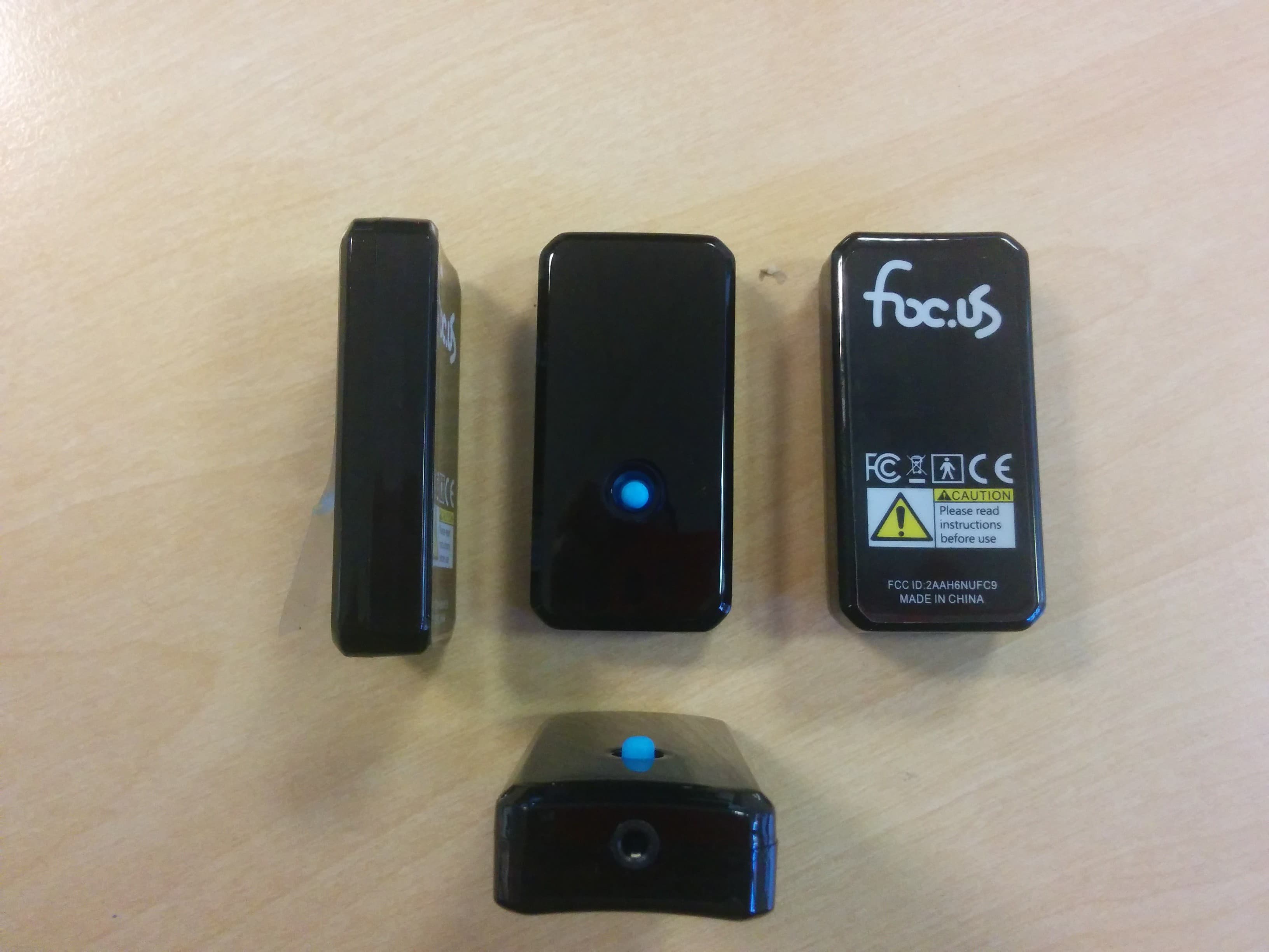
Click to zoom
Application Details
- Equipment Class
- DTS - Digital Transmission System
- Date of Grant
- Mar 25, 2015
- Application Purpose
- Original Equipment
- Date of Application
- Mar 25, 2015
- Equipment Note
- Foc.us v2 controller
- Frequency Range
- 2402.00000000 - 2480.00000000
- Company
- European Engineers Limited
- Country
- United Kingdom
Documents & Files
Document Text
Text extracted from the exhibit documents filed with the FCC. Open a document above to read the original.
Users Manual
1 INSTRUCTIONS 3 Welcome Warning What you need to understand before using foc.us What’s in the box Before starting Getting started Calibrate your foc.us Programs Starting & Stopping a Session Welcome The foc.us v2 is an advanced micro current signal generator. Download the latest version of this manual from: http://www.foc.us/v2/downloads foc.us is designed to be used by healthy adults who do not suffer from epilepsy, brain or mental health conditions or have a metalic implant such as a skull plate, cochlear implant, pace-maker or others. Setup options foc.us dock & software Intended use Bluetooth® connection Troubleshooting Specifications Support Glossary FCC Warranty & Guarantee Contents 3 4 6 9 11 13 15 17 19 20 23 24 24 25 26 26 27 28 29 5 Warning If you suffer from epilepsy, seisures, brain lessions, bipolar depression or severe heart disease you should not use the foc.us headset. If you experience short term negative effects with foc.us you should immediately stop using it. This is not a toy and is not intended to be used by anyone under the age of 18 years old. If using your own electrodes it is not recommended to create novel electrode placements. Do not position the electrodes so that the current may pass through the brainstem. Do not position the electrodes over cuts, grazes or damaged skin. Allow at least 48 hours between usage. Always use the electrodes with wet sponges. Do not touch the metal electrodes as this can lead to burns. 7 What you need to understand before using foc.us foc.us is designed to improve your mental gaming skills. You are exciting and inhibiting sections of your pre-frontal cortex with an electric current. Possible side effects include tingling sensations under the electrodes or on the scalp, visual artifacts, nausea, headaches and fatigue. If you experience any of these you should stop using foc.us. Repeated use may lead to skin irritation. If you exceed the recommended durations you increase the risk of consolidating both the excitatory and inhibitory processes. You may feel a tingling sensation, or a hot or cold sensation. If this is uncomfortable or painful then you should stop session and remove the electrodes. Redness may appear under electrodes after use which will disappear after a short time. Foc.us should not be used during any activities other than seditary gaming. If you see white flashes, or phosphenes you should adjust the position of the headset on your head, pushing it further back away from your eyes. 9 What’s in the box 1. foc.us v2 2. foc.us dock 3. micro-usb cable for recharging 4. this instruction booklet 1. 2. 3. 11 Before starting Firmly push the v2 into the provided dock and connect the dock to a USB power supply to recharge. Install the foc.us software and check for firmware updates. http://www.foc.us/v2/downloads 13 Getting started Wake the foc.us v2 by pressing the blue joystick and holding to turn on. Connect a compatible “Made for foc.us” headset. A list of compatible headsets can be found here: www.foc.us/made-for-focus 15 Calibrate your foc.us The calibration function allows you to find a current level that is comfortable for you. Start the calibrate function and follow the on-screen instructions. You can recalibrate your foc.us at any time by entering the calibrate menu. Ensure sponges are wet before use. 17 blue joystickScreen click to select Programs A program is a combination of settings used during a session. Foc.us ships with two programs - Gamer and Endurance You can create your own program with custom settings. Your calibration settings will override any program settings. 19 Starting & Stopping a Session Follow the onscreen instructions to start a session. You can stop a session at any time from the stop menu onscreen or by vigorously shaking. 21 Setup options The setup menu contains options for language, security and communication settings. Airplane mode - turns off bluetooth PIN - the default PIN is 000000 Reset - reset your foc.us device to factory settings Security - please set your foc.us device to lock to prevent un-authorised usage. Language - if your language is not supported please contact [email protected] Session - foc.us+ session sharing settings Warnings - it is not recommend to use your foc.us more than once every 48 hours. 23 foc.us dock & software The foc.us dock and software can be used to update the firmware of your v2. It can also be used to sync your program and session data with foc.us+ 25 Intended use Use foc.us in accordance with the guidelines of the connected headset WARNING: If you attach external electrodes, make sure you know what you are doing. You have a responsibility to ensure they are not placed in positions that could be dangerous including but not limited to passing current through the brain stem. Bluetooth® connection foc.us can be controlled by bluetooth. Approved apps can be found here: http:// www.foc.us/v2/apps Troubleshooting Problem Solution Cannot turn on Ensure battery is charged by placing in dock Error mode Ensure sponges are wet Battery will not charge check connection of micro-usb to 5v power source. 27 Specifications Size: 56mm x 29mm x 14mm Weight: 21g Battery: 3.7V Li-Po 180mAh rechargable Max current: 2.05mA Max voltage: 60V Bluetooth: 4.0 bluetooth low energy GATT profile FCC ID: 2AAH6NUFC9 Support More information is available on the website: http://help.foc.us/ you can also email [email protected] Glossary Activate start the current flowing between the electrodes Anode positive electrode Cathode negative electrode Montage the positioning of electrodes tDCS transcranial Direct Current Stimulation tRNS transcranial Random Noise Stimulation Phosphenes visual artifacts Sedentary sitting, not physically active 29 FCC FCC warning statement: This device complies with Part 15 of the FCC Rules. Operation is subject to the following two conditions: (1) This device may not cause harmful interference, and (2) This device must accept any interference received, including interference tha…
Text truncated - open the document above for the full version.
Attestation Statements
European Engineers Limited Unit 22, 10 – 12 Marshgate Lane London. E15 2NH. UK. LETTER OF AGENCY December 8 th 2014 TRaC Global Ltd. 100 Frobisher Business Park Malvern Worcestershire WR14 1BX UK To Whom It May Concern: We certify that we are not subject to denial of federal benefits, that includes FCC benefits, pursuant to Section 5301 of the Anti-Drug Abuse ACT of 1988, U.S.C. 862. Further, no party, as defined in 47 CFR 1.2002(b), to the application, is subject to denial of federal benefits, that includes FCC benefits. Thank you for your attention to this matter. Yours faithfully European Engineers Limited Michael Oxley
Cover Letter(s)
European Engineers Limited Unit 22A, 10-12 Marshgate Lane London. E15 2NU. UK REQUEST FOR CONFIDENTIALITY IN ACCORDANCE WITH FCC RULE 0.459 December 8 th , 2014 TRaC GLOBAL LTD. 100 Frobisher Business Park Malvern Worcestershire WR14 1BX UK RE: Certification Application FCC ID:2AAH6NUFC9 To Whom It May Concern: Please be advised that the following information is to be held confidential on behalf of European Engineers Limited Schematics bill of materials track and component layout . The application contains technical information which European Engineers Limited deems to be trade secrets and propriety. If made public, the information might be used to the disadvantage of the applicant in the market place. Thank you for your attention to this matter. Yours faithfully European Engineers Limited Michael Oxley Block Diagram Technical Description
RF Exposure Info
TRaC Global Test Report: TRA-023656-01-47-01A 54 Appendix G: SAR Exclusion & MPE Calculation KDB 447498 Section 4.3 General SAR test reduction and exclusion guidance For Standalone SAR exclusion consideration, when SAR exclusion Threshold requirement in KDB 447498 is satisfied, standalone SAR evaluation for general population exposure conditions by measurement or numerical simulation is not required. In the frequency range 100 MHz to 6 GHz and test separation distance of ≤ 50mm, the SAR Test Exclusion Threshold will be determined as follows SAR Exclusion Threshold (SARET) SAR Exclusion Threshold = Step 1 + Step 2 Step 1 NT = [ (MP/TSD A ) * √ f GHz ] NT = Numeric Threshold (3.0 for 1-g SAR and 7.5 for 10-g SAR) MP = Max Power of channel (mW) (inc tune up) TSD A = Min Test separation Distance or 50mm (whichever is lower) = 5mm (in this case) We can transpose this formula to allow us to find the maximum power of a channel allowed and compare this to the measured maximum power. = [(NT x TSD A ) / √ f GHz ] For Distances Greater than 50 mm Step 2 applies Step 2 (TSD B – 50mm) * 10} Where: TSD B = Min Test separation Distance (mm) = 50 Note: Step 2 is not required here as the TSD A is less than 50mm. TRaC Global Test Report: TRA-023656-01-47-01A 55 Operating Frequency 2.402 GHz SARET = [(3.0 x 5) / √2.402] SARET = 9.68mW Operating Frequency 2.440 GHz SARET = [(3.0 x 5) / √2.440] SARET = 9.60mW Operating Frequency 2.480 GHz SARET = [(3.0 x 5) / √2.480] SARET = 9.53mW Channel Frequency (MHz) EIRP (mW) SAR Exclusion Threshold SAR Evaluation 2402 2.26 9.68 Not Required 2440 1.77 9.60 Not Required 2480 1.35 9.53 Not Required Therefore standalone SAR evaluation for general population exposure conditions by measurement or numerical simulation is not required. Prediction of MPE limit at a given distance Where: S = power density R = distance to the centre of radiation of the antenna EIRP = EUT Maximum power Note: The EIRP was calculated by addition of the maximum conducted carrier power and the maximum antenna gain. Result Prediction Frequency (MHz) Maximum EIRP (mW) Power density limit (S) (mW/cm 2 ) Distance (R) cm Required to be less than 1 mW/cm 2 2402 2.26 1 0.43 4 arranged-re 4 2 S EIRP R R EIRP S
Test Report
A Radio Test Report FOR European Engineers Limited ON foc.us v2 controller Document No. TRA-023656-01-47-01A TRaC Wireless Test Report : TRA-023656-01-47-01A Applicant : European Engineers Limited Apparatus : foc.us v2 controller Specification(s) : CFR47 Part 15.247 FCCID : 2AAH6NUFC9 Purpose of Test : Certification Authorised by : : Radio Product Manager Issue Date : 24 th March 2015 Authorised Copy Number : PDF Total number of pages: 56 TRaC Global Test Report: TRA-023656-01-47-01A Contents Section 1: Introduction 4 1.1 General 4 1.2 Tests Requested By 5 1.3 Manufacturer 5 1.4 Apparatus Assessed 5 1.5 Test Result Summary 6 1.6 Notes Relating To the Assessment 7 1.7 Deviations from Test Standards 7 Section 2: Measurement Uncertainty 8 2.1 Measurement Uncertainty Values 8 Section 3: Modifications 10 3.1 Modifications Performed During Assessment 10 Section 4 General Test Procedures 11 4.1 Radiated Test Setup and Procedures 11 4.2 AC Powerline Conducted Emissions Test Setup and Procedures 12 4.3 Antenna Port Conducted Emissions 12 4.4 Power Supply Variation 13 4.5 Thermal Variation 13 4.6 Time Domain Measurements 13 Appendix A: Formal Emission Test Results 14 A1 6 dB Bandwidth 15 A2 Transmitter Peak Output Power 16 A3 Transmitter Power Spectral Density 17 A4 RF Antenna Conducted Spurious Emissions 18 A5 Radiated Electric Field Emissions 20 A6 Antenna Gain 23 A7 Unintentional Radiated Electric Field Emissions 24 A8 Power Line Conducted Emissions 27 Appendix B: Supporting Graphical Data 29 Appendix C: Additional Test and Sample Details 44 Appendix D: Additional Information 50 Appendix E: Calculation of the duty cycle correction factor 51 Appendix F: Photographs and Figures 52 Appendix G: General SAR test reduction and exclusion guidance 54 3 TRaC Global Test Report: TRA-023656-01-47-01A Section 1: Introduction 1.1 General This report contains an assessment of an apparatus against Electromagnetic Compatibility Standards based upon tests carried out on samples submitted to the Laboratory. Test performed at: TRaC Global [ ] Unit E South Orbital Trading Park Hedon Road Hull, HU9 1NJ. United Kingdom. Telephone: +44 (0) 1482 801801 Fax: +44 (0) 1482 801806 TRaC Global [X] Unit 1 Pendle Place Skelmersdale West Lancashire, WN8 9PN United Kingdom Telephone: +44 (0) 1695 556666 Fax: +44 (0) 1695 577077 Email: [email protected] Web site: http://www.tracglobal.com Tests performed by: A Tosif Report author: A Tosif This report must not be reproduced except in full without prior written permission from TRaC Global. 4 TRaC Global Test Report: TRA-023656-01-47-01A 1.2 Tests Requested By This testing in this report was requested by: European Engineers Limited 16 Beaufort Court London E14 9XL United Kingdom 1.3 Manufacturer As Above 1.4 Apparatus Assessed The following apparatus was assessed between 10 th December 2014 and 15 th January 2015. • foc.us v2 controller The above product is a Bluetooth LE LiPo rechargeable battery powered device operating in the 2.4 GHz ISM band. It has a transceiver for operations with applications installed on a smart phone, or it can operate in single (offline) mode with manual configuration using a single five way joystick. 5 TRaC Global Test Report: TRA-023656-01-47-01A 1.5 Test Result Summary Full details of test results are contained within Appendix A. The following table summarises the results of the assessment. The statements relating to compliance with the standards below apply ONLY as qualified in the notes and deviations stated in sections 1.6 to 1.7 of this test report. Full details of test results are contained within Appendix A. The following table summarises the results of the assessment. Test Type Regulation Measurement standard Result Radiated spurious emissions (Restricted bands) Title 47 of the CFR: Part 15 Subpart C; 15.247 (d) ANSI C63.10:2013 Pass Conducted spurious emissions (Non-restricted bands) Title 47 of the CFR: Part 15 Subpart C; 15.247 (d) ANSI C63.10:2013 Pass AC Power conducted emissions Title 47 of the CFR: Part 15 Subpart C; 15.207 ANSI C63.10:2013 Pass Occupied Bandwidth Title 47 of the CFR : Part 15 Subpart C; 15.247(a)(2) ANSI C63.10:2013 Pass Conducted Carrier Power Title 47 of the CFR : Part 15 Subpart C; 15.247(b) ANSI C63.10:2013 Pass Power Spectral Density Title 47 of the CFR : Part 15 Subpart C; 15.247(e) ANSI C63.10:2013 Pass Unintentional Radiated Spurious Emissions Title 47 of the CFR: Part 15 Subpart B; 15.109 ANSI C63.10:2013 Pass RF Safety KDB 447498 - Pass Abbreviations used in the above table: CFR : Code of Federal Regulations ANSI : American National Standards Institution 6 TRaC Global Test Report: TRA-023656-01-47-01A 1.6 Notes Relating To the Assessment With regard to this assessment, the following points should be noted: The results contained in this report relate only to the items tested and were obtained in the period between the date of initial receipt of samples and the date of issue of the report. The apparatus was set up and exercised using the configurations, modes of operation and arrangements defined in this report only. Particular operating modes, apparatus monitoring methods and performance criteria required by the standards tested to have been performed except where identified in Section 1.7 of this test report (Deviations from Test Standards). For emissions testing, throughout this test report, “Pass” indicates that the results for the sample as tested were below the specified limit (refer also to Section 2, Measurement Uncertainty). Where relevant, the apparatus was only assessed using the monitoring methods and susceptibility criteria defined in this report. All testing with the exception of testing at the Open Area Test Site was performed under the following environmental conditions: Temperature : 17 to 23 °C Humidity : 45 to 75 % Barometric Pressure : 86 to 106 kPa All dates used in this report are in the format dd/mm/yy. This assessment has been performed in accordance with the requirements of ISO/IEC 170…
Text truncated - open the document above for the full version.
Test Setup Photos
TRaC Global Test Report: TRA-023656-01-47-01A Appendix F: Photographs and Figures The following photographs were taken of the test samples: 1. Radiated electric field emissions arrangement: Over view. 2. Radiated electric field emissions arrangement: Close up. 3. AC Powerline Conducted emissions arrangement: Over view. 52 TRaC Global Test Report: TRA-023656-01-47-01A Photograph 1 Photograph 2 Photograph 3 53
Contact Information
Applicant
Michael Oxley(Mr)
Test Firm
Element Materials Technology Warwick LtdStewart Barrowclough
Technical Specifications
| # | Rule Parts | Frequency Range | Power Output |
|---|---|---|---|
| 1 | 15C | 2.40 GHz - 2.48 GHz | 640.00 µW |
Other Applications from European Engineers Limited
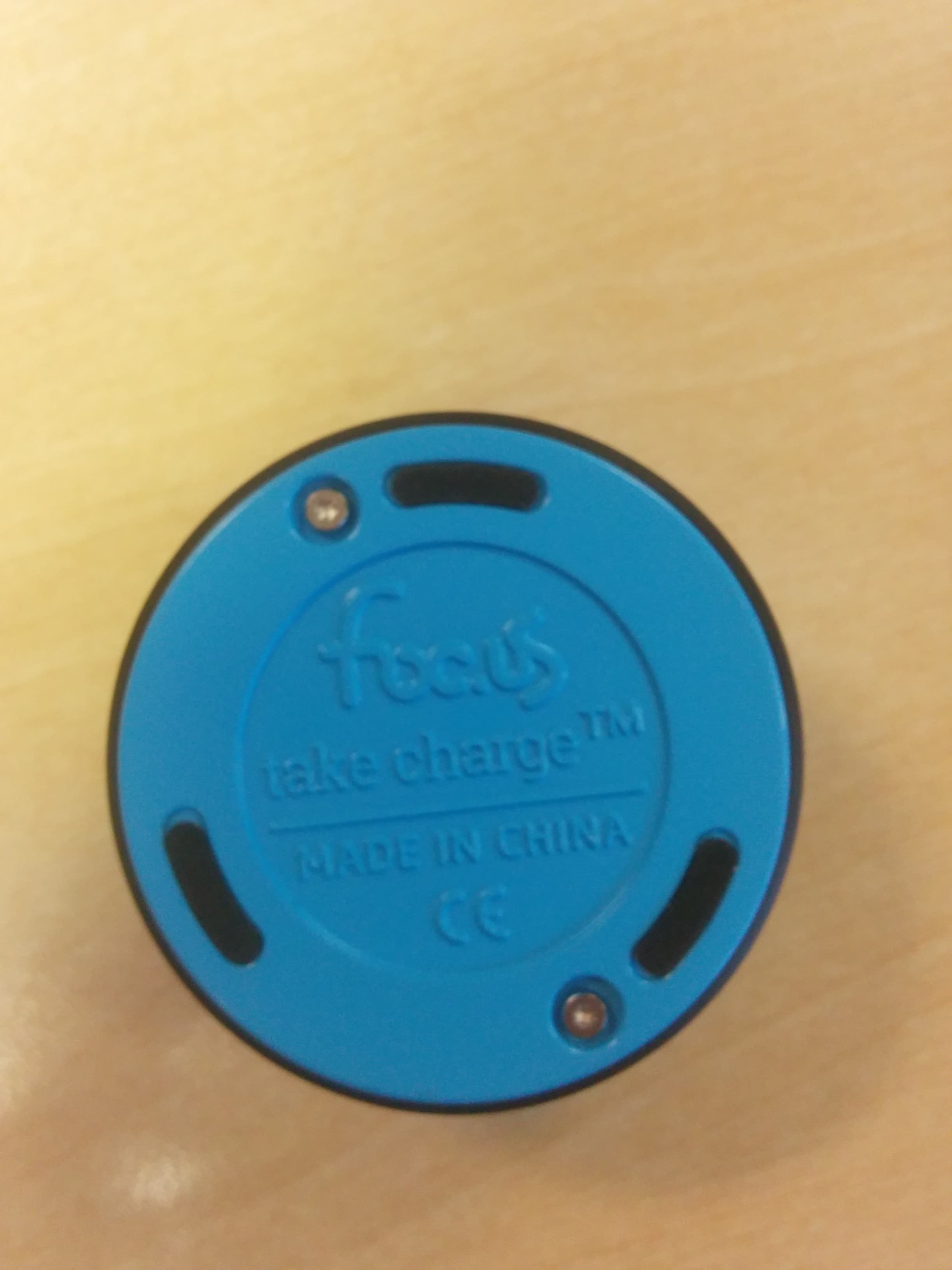
2AAH6DOCK1
Mar 25, 2015Foc.us dock and recharge
Equipment Class
DTS - Digital Transmission System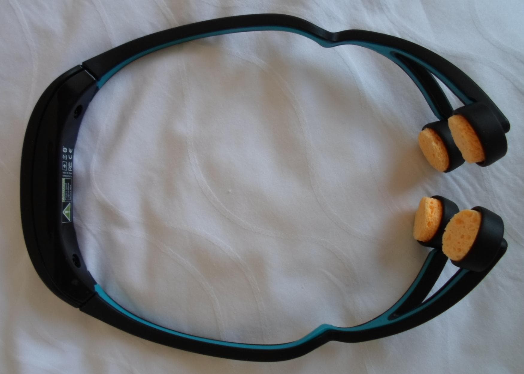
2AAH6DLIG1
Jul 26, 2013Foc.us gamer headset
Equipment Class
DTS - Digital Transmission System