2AAHG-SGW101020NFC-USB Gateway
SISTELNETWORKS S.L.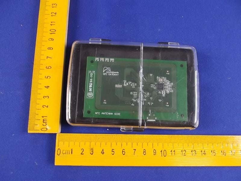
Click to zoom
Application Details
- Equipment Class
- DXX - Part 15 Low Power Communication Device Transmitter
- Date of Grant
- Jul 07, 2014
- Application Purpose
- Original Equipment
- Date of Application
- Jul 07, 2014
- Equipment Note
- NFC-USB Gateway
- Frequency Range
- 13.56000000 - 13.56000000
- Company
- SISTELNETWORKS S.L.
- Country
- Spain
Documents & Files
Document Text
Text extracted from the exhibit documents filed with the FCC. Open a document above to read the original.
Users Manual
Sistelnetworks S.L. Ronda Narciso Monturiol, 6 Office 109 B 46980 Paterna Valencia, Spain T: +34 961 36 65 33 F: +34 961 31 83 83 www.sistelnetworks.com [email protected] NFC-USB Gateway Module User Manual and technical information v1.0 Gateway NFC USB module Page 1 of 5 INDEX INDEX ............................................................................................................................................. 1 Copyrights ..................................................................................................................................... 2 Trademarks.................................................................................................................................... 2 Changes ......................................................................................................................................... 2 Health, Safety and General use Precautions ................................................................................. 2 1. Description ............................................................................................................................ 3 2. User interface ........................................................................................................................ 3 2.1. Power ................................................................................................................................ 3 2.2. LED Indications .................................................................................................................. 3 2.3. FW Upgrade ....................................................................................................................... 3 3. Host controller Interface ....................................................................................................... 4 4. Commands supported ........................................................................................................... 4 4.1. Configuration and Control Commands ............................................................................. 4 4.2. P2P Commands ................................................................................................................. 4 5. Errors Description.................................................................................................................. 5 Gateway NFC USB module Page 2 of 5 COPYRIGHTS Copyright © 2014 Sistelnetworks. All rights reserved. No part of this publication may be reproduced, stored in a retrieval system, or transmitted in any form or by any means, electronic, mechanical, photocopying, recording or otherwise, without the prior written consent of Sistelnetworks. TRADEMARKS All trademarks mentioned in this manual are the property of their respective owners. CHANGES The material in this document is for information only and is subject to change without notice. While reasonable efforts have been made in the preparation of this document to assure its accuracy, LaCie assumes no liability resulting from errors or omissions in this document, or from the use of the information contained herein. LaCie reserves the right to make changes or revisions in the product design or the product manual without reservation and without obligation to notify any person of such revisions and changes. HEALTH, SAFETY AND GENERAL USE PRECAUTIONS Read this User's Manual carefully, and follow the correct procedure when setting up the device. Never expose your module to rain or use it near water or in damp or wet conditions. Never place containers on it containing liquids that may spill into its openings. Doing so increases the risk of electrical shock, short-circuiting, fire or personal injury. Do not expose the drive to temperatures outside the range of 5° C to 40° C (41° F to 104° F) during operation. Doing so may damage the drive or disfigure its casing. Avoid placing your drive near a source of heat or exposing it to sunlight (even through a window). Inversely, placing your drive in an environment that is too cold or humid may damage the unit. Always unplug the drive if there is a risk of lightning or if it will not be used for an extended period of time. Otherwise, there is an increased risk of electrical shock, short-circuiting or fire. Do not place heavy objects on top of the drive or use excessive force on its buttons, connectors and tray. Doing so increases the risk of damage to the device. Whatever you’re planning to do with your Gateway module, make sure you give it the respect it deserves. It may be small, but it is just as prone to damage from static electricity and knocks and blows – not to mention extremes of temperature – as any other computer. As such, you should remove all jewelry and static-attracting garments (nylon and other manufactured fibers, as well as wool), handle the device in a clean, dust-free area with a solid, non-carpeted floor and make sure that you have clean hands and have earthed yourself. Gateway NFC USB module Page 3 of 5 1. DESCRIPTION The NFC-USB Gateway module is a highly integrated NFC(Near Field Communications) electronic module able to perform P2P (Peer to Peer) communications with NFC devices. This module is connected via microUSB to other devices for control, transmission and reception of information. Also the module is powered via USB connector. Another device, in general a computer, smart phone or any other device with NFC or USB capabilities controls all the functionalities of the Gateway module. 2. USER INTERFACE 2.1. POWER The device is USB powered. 2.2. LED INDICATIONS The Gateway has four LEDs to show the status of the device: LED COLOUR FUNCTIONALITY ACTION WHITE Power ON: Gateway active Light on ORANGE NFC P2P operation being performed Light on GREEN NFC operation finished correctly Light on RED NFC operation finished with errors Light on Table 1. LED Indications 2.3. FW UPGRADE FW upgrade is performed through the microUSB connector. The host controller sends one…
Text truncated - open the document above for the full version.
Users Manual
Sistelnetworks S.L. Ronda Narciso Monturiol, 6 Office 109 B 46980 Paterna Valencia, Spain T: +34 961 36 65 33 F: +34 961 31 83 83 www.sistelnetworks.com [email protected] NFC-USB Gateway Module User Manual and technical information v1.0 Gateway NFC USB module Page 1 of 5 INDEX INDEX ............................................................................................................................................. 1 Copyrights ..................................................................................................................................... 2 Trademarks.................................................................................................................................... 2 Changes ......................................................................................................................................... 2 Health, Safety and General use Precautions ................................................................................. 2 1. Description ............................................................................................................................ 3 2. User interface ........................................................................................................................ 3 2.1. Power ................................................................................................................................ 3 2.2. LED Indications .................................................................................................................. 3 2.3. FW Upgrade ....................................................................................................................... 3 3. Host controller Interface ....................................................................................................... 4 4. Commands supported ........................................................................................................... 4 4.1. Configuration and Control Commands ............................................................................. 4 4.2. P2P Commands ................................................................................................................. 4 5. Errors Description.................................................................................................................. 5 Gateway NFC USB module Page 2 of 5 COPYRIGHTS Copyright © 2014 Sistelnetworks. All rights reserved. No part of this publication may be reproduced, stored in a retrieval system, or transmitted in any form or by any means, electronic, mechanical, photocopying, recording or otherwise, without the prior written consent of Sistelnetworks. TRADEMARKS All trademarks mentioned in this manual are the property of their respective owners. CHANGES The material in this document is for information only and is subject to change without notice. While reasonable efforts have been made in the preparation of this document to assure its accuracy, LaCie assumes no liability resulting from errors or omissions in this document, or from the use of the information contained herein. LaCie reserves the right to make changes or revisions in the product design or the product manual without reservation and without obligation to notify any person of such revisions and changes. HEALTH, SAFETY AND GENERAL USE PRECAUTIONS Read this User's Manual carefully, and follow the correct procedure when setting up the device. Never expose your module to rain or use it near water or in damp or wet conditions. Never place containers on it containing liquids that may spill into its openings. Doing so increases the risk of electrical shock, short-circuiting, fire or personal injury. Do not expose the drive to temperatures outside the range of 5° C to 40° C (41° F to 104° F) during operation. Doing so may damage the drive or disfigure its casing. Avoid placing your drive near a source of heat or exposing it to sunlight (even through a window). Inversely, placing your drive in an environment that is too cold or humid may damage the unit. Always unplug the drive if there is a risk of lightning or if it will not be used for an extended period of time. Otherwise, there is an increased risk of electrical shock, short-circuiting or fire. Do not place heavy objects on top of the drive or use excessive force on its buttons, connectors and tray. Doing so increases the risk of damage to the device. Whatever you’re planning to do with your Gateway module, make sure you give it the respect it deserves. It may be small, but it is just as prone to damage from static electricity and knocks and blows – not to mention extremes of temperature – as any other computer. As such, you should remove all jewelry and static-attracting garments (nylon and other manufactured fibers, as well as wool), handle the device in a clean, dust-free area with a solid, non-carpeted floor and make sure that you have clean hands and have earthed yourself. Gateway NFC USB module Page 3 of 5 1. DESCRIPTION The NFC-USB Gateway module is a highly integrated NFC(Near Field Communications) electronic module able to perform P2P (Peer to Peer) communications with NFC devices. This module is connected via microUSB to other devices for control, transmission and reception of information. Also the module is powered via USB connector. Another device, in general a computer, smart phone or any other device with NFC or USB capabilities controls all the functionalities of the Gateway module. 2. USER INTERFACE 2.1. POWER The device is USB powered. 2.2. LED INDICATIONS The Gateway has four LEDs to show the status of the device: LED COLOUR FUNCTIONALITY ACTION WHITE Power ON: Gateway active Light on ORANGE NFC P2P operation being performed Light on GREEN NFC operation finished correctly Light on RED NFC operation finished with errors Light on Table 1. LED Indications 2.3. FW UPGRADE FW upgrade is performed through the microUSB connector. The host controller sends one…
Text truncated - open the document above for the full version.
Users Manual
Sistelnetworks S.L. Ronda Narciso Monturiol, 6 Office 109 B 46980 Paterna Valencia, Spain T: +34 961 36 65 33 F: +34 961 31 83 83 www.sistelnetworks.com [email protected] NFC-USB Gateway Module User Manual and technical information v1.0 Gateway NFC USB module Page 1 of 5 INDEX INDEX ............................................................................................................................................. 1 Copyrights ..................................................................................................................................... 2 Trademarks.................................................................................................................................... 2 Changes ......................................................................................................................................... 2 Health, Safety and General use Precautions ................................................................................. 2 1. Description ............................................................................................................................ 3 2. User interface ........................................................................................................................ 3 2.1. Power ................................................................................................................................ 3 2.2. LED Indications .................................................................................................................. 3 2.3. FW Upgrade ....................................................................................................................... 3 3. Host controller Interface ....................................................................................................... 4 4. Commands supported ........................................................................................................... 4 4.1. Configuration and Control Commands ............................................................................. 4 4.2. P2P Commands ................................................................................................................. 4 5. Errors Description.................................................................................................................. 5 Gateway NFC USB module Page 2 of 5 COPYRIGHTS Copyright © 2014 Sistelnetworks. All rights reserved. No part of this publication may be reproduced, stored in a retrieval system, or transmitted in any form or by any means, electronic, mechanical, photocopying, recording or otherwise, without the prior written consent of Sistelnetworks. TRADEMARKS All trademarks mentioned in this manual are the property of their respective owners. CHANGES The material in this document is for information only and is subject to change without notice. While reasonable efforts have been made in the preparation of this document to assure its accuracy, LaCie assumes no liability resulting from errors or omissions in this document, or from the use of the information contained herein. LaCie reserves the right to make changes or revisions in the product design or the product manual without reservation and without obligation to notify any person of such revisions and changes. HEALTH, SAFETY AND GENERAL USE PRECAUTIONS Read this User's Manual carefully, and follow the correct procedure when setting up the device. Never expose your module to rain or use it near water or in damp or wet conditions. Never place containers on it containing liquids that may spill into its openings. Doing so increases the risk of electrical shock, short-circuiting, fire or personal injury. Do not expose the drive to temperatures outside the range of 5° C to 40° C (41° F to 104° F) during operation. Doing so may damage the drive or disfigure its casing. Avoid placing your drive near a source of heat or exposing it to sunlight (even through a window). Inversely, placing your drive in an environment that is too cold or humid may damage the unit. Always unplug the drive if there is a risk of lightning or if it will not be used for an extended period of time. Otherwise, there is an increased risk of electrical shock, short-circuiting or fire. Do not place heavy objects on top of the drive or use excessive force on its buttons, connectors and tray. Doing so increases the risk of damage to the device. Whatever you’re planning to do with your Gateway module, make sure you give it the respect it deserves. It may be small, but it is just as prone to damage from static electricity and knocks and blows – not to mention extremes of temperature – as any other computer. As such, you should remove all jewelry and static-attracting garments (nylon and other manufactured fibers, as well as wool), handle the device in a clean, dust-free area with a solid, non-carpeted floor and make sure that you have clean hands and have earthed yourself. Gateway NFC USB module Page 3 of 5 1. DESCRIPTION The NFC-USB Gateway module is a highly integrated NFC(Near Field Communications) electronic module able to perform P2P (Peer to Peer) communications with NFC devices. This module is connected via microUSB to other devices for control, transmission and reception of information. Also the module is powered via USB connector. Another device, in general a computer, smart phone or any other device with NFC or USB capabilities controls all the functionalities of the Gateway module. 2. USER INTERFACE 2.1. POWER The device is USB powered. 2.2. LED INDICATIONS The Gateway has four LEDs to show the status of the device: LED COLOUR FUNCTIONALITY ACTION WHITE Power ON: Gateway active Light on ORANGE NFC P2P operation being performed Light on GREEN NFC operation finished correctly Light on RED NFC operation finished with errors Light on Table 1. LED Indications 2.3. FW UPGRADE FW upgrade is performed through the microUSB connector. The host controller sends one…
Text truncated - open the document above for the full version.
Cover Letter(s)
SISTELNETWORKS S.L. FCC Modular Approval Request Number:CF305 Version: V04 Date: 07-08-2012 To the FCC or FCC TCB handling this application Hereby we, Company name (grantee) SISTELNETWORKS S.L. Addresss Ronda Narciso Monturiol 6, Dpcho. 109B, 46980, City / ZIP / State / Country Paterna, Spain request modular approval for the certification of our equipment within this application, identified by: FCC ID: 2AAHG-SGW101020 The table below contains the justification for modular approval of this equipment: Requirement per 15.212 and KDB 996369 D01 Module Certification Guide v01r03Explanation from grantee (do not write yes / no, but explain why it complies / how it is achieved) 1. The modular transmitter must have its own RF shielding. No, the modular is only a PCB board. 2. The modular transmitter must have buffered modulation/data inputs (if such inputs are provided) to ensure that the module will comply with Part 15 requirements under conditions of excessive data rates or over-modulation. The modular has buffered data inputs, it is integrated in chip MSP430F6638IPZ. 3. The modular transmitter must have its own power supply regulation. No, DC 5V is fed from the host. 4. The modular transmitter must comply with the antenna requirements of Section 15.203 and 15.204(c). The antenna must either be permanently attached or employ a “unique” antenna coupler (at all connections between the module and the antenna, including the cable).. The antenna of module meets the FCC antenna requirements. 5. The modular transmitter must be tested in a stand-alone configuration, i.e., the module must not be inside another device during testing. This is intended to demonstrate that the module is capable of complying with Part 15 emission limits regardless of the device into which it is eventually installed. The module was tested in a stand-alone configuration. 6. The modular transmitter must be labeled with its own FCC ID number, and, if the FCC ID is not visible when the module is installed inside another device, then the outside of the device into which the module is installed must also display a label referring to the enclosed module. This exterior label can use wording such as the following: “Contains Transmitter Module FCC ID: XYZMODEL1” or “Contains FCC ID: XYZMODEL1.” Any similar wording that expresses the same meaning may be used. The Grantee may either provide such a label, an example of which must be included in the application for equipment authorization, or, must provide adequate instructions along with the module which explain this requirement. In the latter case, a copy of these instructions must be included in the application for equipment authorization. The label position of FCC ID is clearly indicated. Please see the label location. And also described clearly in users manual. 7. The modular transmitter must comply with any specific rule or operating requirements applicable to the transmitter and the manufacturer must provide adequate instructions along with the module to explain any such requirements. A copy of these instructions must be included in the application for equipment authorization. For example, there are very strict operational and timing requirements that must be met before a transmitter is authorized for operation under Section 15.231. For instance, data transmission is prohibited, except for operation under Section 15.231(e), in which case there are separate field strength level and timing requirements. Compliance with these requirements must be assured. The module is compliant with all applicable FCC rules. Datail instructions are given in the Users Manual. 8. The modular transmitter must comply with any applicable RF exposure requirements. For example, FCC Rules in Sections 2.1091, 2.1093 and specific Sections of Part 15, including 15.319(i), 15.407(f), 15.253(f) and 15.255(g), require that Unlicensed PCS, UNII and millimeter wave devices perform routine environmental evaluation for RF Exposure to demonstrate compliance. In addition, spread spectrum transmitters operating under Section 15.247 are required to address RF Exposure compliance in accordance with Section 15.247(b)(4). Modular transmitters approved under other Sections of Part 15, when necessary, may also need to address certain RF Exposure concerns, typically by providing specific installation and operating instructions for users, installers and other interested parties to ensure compliance. The module is a low power transmitter, and complies with any applicable RF exposure requirements. Attestation (by grantee) City and Country: Date: Name: (this must be a person) Function:Signature: (or official company stamp) Paterna, Spain 2014-06-30 Jose LuisVilarCEO
Cover Letter(s)
SISTELNETWORKS S.L. FCC Confidentiality Request Number: CF303 Version: V05 Date: 21-05-2012 (Permanent or also called long term confidentiality is the normal method to keep certain docuements confidential, and may apply to schematics, block diagrams, operational description and bill of materials.) To: Federal Communications Commission Equipment Authorization Branch 7435 Oakland Mills Road Columbia, MD 21046 Pursuant to 47 CFR Section 0.459(a) & (b), we, (the applicant / grantee) Company name SISTELNETWORKS S.L. Address Ronda Narciso Monturiol 6, Dpcho. 109B, 46980, City Paterna Country Spain request for this certification filing under: Grantee Code Product Number FCC ID: 2AAHG-SGW101020 to maintain permanent confidentiality for the following documents submitted within this application: (please cross what is applicable, or add other documents, provide the file name and description) Exhibit File Name Description √ Operational Description Operational Description explaining the functioning of the block diagram √ Block Diagrams Block Diagrams showing the systematic building blocks of the EUT √ Schematics Diagrams Schematics showing components, their values and interconnection Bill of Materials List of components used on the PCB’s of the EUT Above materials crossed contain secrets, proprietary and technical information, which would customarily be guarded from competitors under 47 CFR, section 0.457(d)(2). Disclosure or publication or any portion of this company confidential material to other parties could cause substantial competitive harm and provide unjustified benefits for competitors. We understand that pursuant to 47 CFR section 0.457(d)(1)(ii) disclosure of the applicant and all accompanying documentation will not be made before the date of the grant. The documents indicated as confidential above, are not publicly available elsewhere. Attestation: City and Country: Date: Name: (this must be a person) Function:Signature: (or official company stamp) Paterna, Spain 2014-06-30 Jose LuisVilarCEO
Cover Letter(s)
SISTELNETWORKS S.L. FCC Modular Approval Request Number:CF305 Version: V04 Date: 07-08-2012 To the FCC or FCC TCB handling this application Hereby we, Company name (grantee) SISTELNETWORKS S.L. Addresss Ronda Narciso Monturiol 6, Dpcho. 109B, 46980, City / ZIP / State / Country Paterna, Spain request modular approval for the certification of our equipment within this application, identified by: FCC ID: 2AAHG-SGW101020 The table below contains the justification for modular approval of this equipment: Requirement per 15.212 and KDB 996369 D01 Module Certification Guide v01r03Explanation from grantee (do not write yes / no, but explain why it complies / how it is achieved) 1. The modular transmitter must have its own RF shielding. No, the modular is only a PCB board. 2. The modular transmitter must have buffered modulation/data inputs (if such inputs are provided) to ensure that the module will comply with Part 15 requirements under conditions of excessive data rates or over-modulation. The modular has buffered data inputs, it is integrated in chip MSP430F6638IPZ. 3. The modular transmitter must have its own power supply regulation. No, DC 5V is fed from the host. 4. The modular transmitter must comply with the antenna requirements of Section 15.203 and 15.204(c). The antenna must either be permanently attached or employ a “unique” antenna coupler (at all connections between the module and the antenna, including the cable).. The antenna of module meets the FCC antenna requirements. 5. The modular transmitter must be tested in a stand-alone configuration, i.e., the module must not be inside another device during testing. This is intended to demonstrate that the module is capable of complying with Part 15 emission limits regardless of the device into which it is eventually installed. The module was tested in a stand-alone configuration. 6. The modular transmitter must be labeled with its own FCC ID number, and, if the FCC ID is not visible when the module is installed inside another device, then the outside of the device into which the module is installed must also display a label referring to the enclosed module. This exterior label can use wording such as the following: “Contains Transmitter Module FCC ID: XYZMODEL1” or “Contains FCC ID: XYZMODEL1.” Any similar wording that expresses the same meaning may be used. The Grantee may either provide such a label, an example of which must be included in the application for equipment authorization, or, must provide adequate instructions along with the module which explain this requirement. In the latter case, a copy of these instructions must be included in the application for equipment authorization. The label position of FCC ID is clearly indicated. Please see the label location. And also described clearly in users manual. 7. The modular transmitter must comply with any specific rule or operating requirements applicable to the transmitter and the manufacturer must provide adequate instructions along with the module to explain any such requirements. A copy of these instructions must be included in the application for equipment authorization. For example, there are very strict operational and timing requirements that must be met before a transmitter is authorized for operation under Section 15.231. For instance, data transmission is prohibited, except for operation under Section 15.231(e), in which case there are separate field strength level and timing requirements. Compliance with these requirements must be assured. The module is compliant with all applicable FCC rules. Datail instructions are given in the Users Manual. 8. The modular transmitter must comply with any applicable RF exposure requirements. For example, FCC Rules in Sections 2.1091, 2.1093 and specific Sections of Part 15, including 15.319(i), 15.407(f), 15.253(f) and 15.255(g), require that Unlicensed PCS, UNII and millimeter wave devices perform routine environmental evaluation for RF Exposure to demonstrate compliance. In addition, spread spectrum transmitters operating under Section 15.247 are required to address RF Exposure compliance in accordance with Section 15.247(b)(4). Modular transmitters approved under other Sections of Part 15, when necessary, may also need to address certain RF Exposure concerns, typically by providing specific installation and operating instructions for users, installers and other interested parties to ensure compliance. The module is a low power transmitter, and complies with any applicable RF exposure requirements. Attestation (by grantee) City and Country: Date: Name: (this must be a person) Function:Signature: (or official company stamp) Paterna, Spain 2014-06-30 Jose LuisVilarCEO
Cover Letter(s)
SISTELNETWORKS S.L. FCC Confidentiality Request Number: CF303 Version: V05 Date: 21-05-2012 (Permanent or also called long term confidentiality is the normal method to keep certain docuements confidential, and may apply to schematics, block diagrams, operational description and bill of materials.) To: Federal Communications Commission Equipment Authorization Branch 7435 Oakland Mills Road Columbia, MD 21046 Pursuant to 47 CFR Section 0.459(a) & (b), we, (the applicant / grantee) Company name SISTELNETWORKS S.L. Address Ronda Narciso Monturiol 6, Dpcho. …
Text truncated - open the document above for the full version.
Contact Information
Applicant
Jose Luis Vilar(CEO)
Technical Contact
Test Firm
Shenzhen Anbotek Compliance Laboratory LimitedDaniel zhu
[email protected]86-755-26014771
Technical Specifications
| # | Rule Parts | Frequency Range | Power Output |
|---|---|---|---|
| 1 | 15C | 13.56 MHz - 13.56 MHz | - |