2AAJ4-V5Bluetooth Interphone
Shenzhen xinlangrui electronic co.,ltd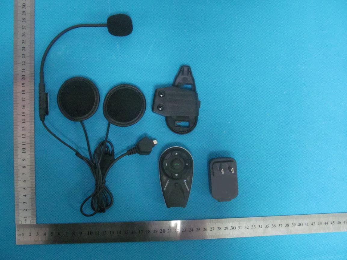
Click to zoom
Application Details
- Equipment Class
- DSS - Part 15 Spread Spectrum Transmitter
- Date of Grant
- Aug 12, 2013
- Application Purpose
- Original Equipment
- Date of Application
- Aug 12, 2013
- Equipment Note
- Bluetooth Interphone
- Frequency Range
- 2402.00000000 - 2480.00000000
- Country
- China
Documents & Files
Document Text
Text extracted from the exhibit documents filed with the FCC. Open a document above to read the original.
Users Manual
User Manual bluetooth interphone Model Name: V5 Brand Name: BTI FCC ID: 2AAJ4-V5 1: Power on 2: Power off 3:Volume + 4:Volume - 5: FM radio on/Rider A 6:Rider B 7: Snap joint 8:Plug Installation instruction Find a proper location to fix the clamp Install bluetooth interphone onto the clamp under instruction Finished installation Earphone line connecting instruction power on: press the power on button, approx. 2 seconds, until red light,and then blue light flash Pairing with bluetooth equipment instruction 2: Pairing with cellphone/MP3/GPS,after power on,press key 1 about 3-5 seconds, with red and blue flash light,open the cellphone/MP3/GPS bluetooth function, when searching,see left photo, press connecting,pairing successful when red flash off, blue light flash rhythmically. FM function: Bluetooth interphone power on,with earphone, press Rider A key for 3s. Pairing with the other V2,each equipment has power on, 1) Press Rider A at the same time for 5-7s,till the red and blue light flash alternately. 2) Press either equipment Rider A,till red light off, blue light flash,at the searching situation. after 5-7 seconds,the other equipment red light off, blue light flash. pairing successful 3) Press either equipment Rider A,can talk with each other The red and blue flash appreance alternately 4 parties pairing: 1) Equipment 1 and 2 as pairs,3 and 4 as pairs, and make them paring as model A. 2) Choose 2 and 3 pairs as model B, press key Rider B for 3-5s,till the red and blue light flash alternately. press either key Rider B of equipment 2 or 3,till red light off, blue light flash, mean at the searching situation. after 5-7s,the other equipment red light off, blue light flash. connecting successful,press either key Rider B,equipment 2 and 3 paring successful. 3) Press Rider A of equipment 1 or 4, four riders conneting,can talk to each other 4) Paring equipment 4 and 5, press key Rider B of equipment 4 and Rider A of equipment 5 for 3-5s, red and blue light flash alternately, then press Rider B of equipment 4(or Rider A of equipment 5,either is ok), till red light off and blue light flash,mean ath the searching situation,after 5-7s, red light off, blue light flash, paring successfully, then press Rider B of equipment 4(or Rider A of equipment 5), 5 Riders can talk to each other at the same time. 5) Equipment 1 and 5, press Rider B till red and blue light flash alternately,equipment 1 and 5 connect to cellphone( see last page paring to cellphone) (PS: cancel the paring of V4:press any one of the 4 equipment Rider A and Rider B after 3s, red and blue flash alternately, connecting cancellation) Remark: when phone call, will receive priority automately, and will back to 5 riders talking model after phone call finish,also automately. V2 paring instruction Accessories USB charger lead Earphone Clamp connected and installed unit AC&USB charger Important Regular Information This device complies with part 15 of the FCC rules. Operation is subject to the following two conditions: (1) this device may not cause harmful interference, and (2) this device must accept any interference received, including interference that may cause undesired operation. Changes or modifications to this unit not expressly approved by the party responsible for compliance could void the user’s authority to operate the equipment. RF Exposure Information: FCC RF Exposure requirements: The highest SAR value reported under this standard during product certification for use next to the head with the minimum separation distance of 10mm is 0. 479 W/kg. This transmitter must not be collocated or operating in conjunction with any other antenna or transmitter.
Cover Letter(s)
13-8-13OET Inquiry System Inquiry Tracking Number 762790 https://apps.fcc.gov/oetcf/kdb/forms/ReplyToResponse2.cfm1/5 Search|RSS |Updates |E-Filing |Initiatives |Consumers |Find People Office of Engineering and Technology FCC > FCC E-filing > Inquiry System Home Page > View InquiryFCC Site Map OET Home Page Site Options Basic KDB Search Advanced KDB Search Submit an Inquiry Reply to an Inquiry Response Category List FAQ Search Major Guidance Publications Draft Laboratory Division Publications Draft Laboratory Division Publications (Expired) Draft Publication Moderation Policy Related Sites Equipment Authorization Presentations Equipment Authorization System (EAS) Telecommunications Certification Bodies (TCB) Reply to an OET Inquiry Response Currently Displaying Inquiry Tracking Number: 762790 Contact Information: Customer First Name:yimi Customer Last Name:zhao Telephone Number: 8613715388250 Extension: E-mail Address: [email protected] Address: Line 1:xixiang shanwei Line 2:xixiang shanwei P.O. Box: City:Shenzhen State: Zip Code:518000 Country:China Inquiry Details on 07/12/2013: First category: RF Exposure * Second category: SAR (RF Exposure) Third category: Subject:SAR test procedure Inquiry:Dear Sir, 13-8-13OET Inquiry System Inquiry Tracking Number 762790 https://apps.fcc.gov/oetcf/kdb/forms/ReplyToResponse2.cfm2/5 Could you please help us to confirm the SAR test procedure for this kind of device kindly, It's a helmet mounted which operated in 2402~2480MHz.The Max RF output power is 16.32dBm. Please refer the attachment for more details. Looking forward for your support. Thank you. Best Regards! FCC Response on 07/16/2013: Please answer the following questions: i. Can the device be installed on more than one brand/model of helmet or is there an exclusive helmet this device is to be used with? If it can be installed on different brands/models how many? ii. If it is to be used with an exclusive helmet, how do you ensure that the device cannot be installed on any other brand/model of helmet? iii. What is the closest separation distance between the device and the user during operation? This may vary if this device can be used on more than one brand/model of helmet. iv. In the photos of the device there appears to be a mounting bracket used to attach the device to the helmet. Does this mounting bracket contain any metal? v. After the device has been mounted to the helmet is it removable or is it permanently attached? vi. After the device has been mounted to the helmet is it rotatable? vii. If possible, please provide the complete measured time averaged conducted powers. ---Reply from Customer on 07/22/2013--- Dear Sir, Please refer below; i. Can the device be installed on more than one brand/model of helmet or is there an exclusive helmet this device is to be used with? If it can be installed on different brands/models how many? An: This device can connect with any helmets which have bluetooth function, no exclusive helmet required. ii. If it is to be used with an exclusive helmet, how do you ensure that the device cannot be installed on any other brand/model of helmet? An: No exclusive helmet 13-8-13OET Inquiry System Inquiry Tracking Number 762790 https://apps.fcc.gov/oetcf/kdb/forms/ReplyToResponse2.cfm3/5 required. iii. What is the closest separation distance between the device and the user during operation? This may vary if this device can be used on more than one brand/model of helmet. An: The most closed separation between the deivce and the user should be 10mm. iv. In the photos of the device there appears to be a mounting bracket used to attach the device to the helmet. Does this mounting bracket contain any metal? An: The mounting bracket is made of plastic, no metal included. v. After the device has been mounted to the helmet is it removable or is it permanently attached? vi. After the device has been mounted to the helmet is it rotatable? An: After the device has been mounted to the helmet, It's non-rotatable, and can removed from the helmet anytime. vii. If possible, please provide the complete measured time averaged conducted powers. An: conducted power please refer the attachment. FCC Response on 07/22/2013: Please provide SAR test data for the side that will face the user’s head during operation. Apply the following guidance: i. Use the flat phantom for testing. ii. Use a test separation distance of 10 mm away from the phantom (This separation distance was chosen based on the information you provided regarding the minimum separation distance between the device and the user during operation). iii. Use Head Tissue Simulating Liquid for the test. iv. Do not use the mounting bracket during the tests (Since the mounting bracket does not contain any metal it should not significantly affect the SAR results). After conducting the SAR tests prepare a SAR report and respond to this inquiry with the report as an attachment. After reviewing the report, final approval to submit the report to a TCB for grant will then be given. Do not submit the SAR report to TCB for grant until the FCC has reviewed the SAR results. Additionally, in the SAR report please add the following statements, “A non-standard setup was used for SAR testing based on guidance from the FCC. The operational description contains additional information.” Then add a statement in the operational description referencing this KDB Inquiry number (This is because the KDB Inquiry number is confidential but the SAR Report will be on public record). If you have any questions regarding this guidance please do not hesitate to ask. 13-8-13OET Inquiry System Inquiry Tracking Number 762790 https://apps.fcc.gov/oetcf/kdb/forms/ReplyToResponse2.cfm4/5 ---Reply from Customer on 07/31/2013--- Dear Sir, Thanks for your guidance, Please check the SAR report attached and help us to confirm is it acceptable now? Looking forward for your reply. Thanks again. FCC Response on 08/09/2013: Upon review of the “SAR report” provided, the resul…
Text truncated - open the document above for the full version.
Cover Letter(s)
June 24, 2013 Federal Communication Commission Authorization and Evaluation Division FCC ID: 2AAJ4-V5 Re: Confidentiality Request Pursuant to Sections 0.457 and 0.459 of the Commission’s Rules, the applicant hereby requests confidential treatment of information applied this application as outlined below: 1: Block Diagram 2: Circuit Diagram 3: Operational Description 4: Parts List 5: Tune Up Procedure The above materials contain trade secrets and proprietary information not customarily released to the public. The public disclosure of these matters might be harmful to the applicant and provide unjustified benefits to its competitors. The Applicant understands that pursuant to Rules 0.457, disclosure of this Application and all accompanying documentation will not be made before the date of the Grant for this application. Sincerely, Shenzhen xinlangrui electronic co.,ltd Contact person: Kenny Gong Title: Manager Tel: 0755-29037481
External Photos
V5_External Photos TOTAL VIEW OF EUT TOP VIEW OF EUT BOTTOM VIEW OF EUT FRONT VIEW OF EUT BACK VIEW OF EUT LEFT VIEW OF EUT RIGHT VIEW OF EUT
ID Label/Location Info
FCC ID Label Location bluetooth interphone Model: V5 Brand Name: BTI FCC ID: 2AAJ4-V5 V4, V2, V6, V8
Internal Photos
V5_Internal Photos OPEN VIEW OF EUT INTERNAL VIEW OF EUT-1 INTERNAL VIEW OF EUT-2 BT Antenna
RF Exposure Info
FCC ID APPLIC PRODU BRAND MODEL CLIENT DATE O STAND REPOR A CAUTIO This rep laborato CATION PUR UCT DESIGN D NAME L NAME T OF ISSUE DARD(S) RT VERSION Attestat ON: port shall n ory and sha SA Rep : RPOSE NATION : : : : : : : tion of G not be repro all not be q R Te port No.: A 2AAJ4‐V 5 Original E bluetoot h BTI V2, V4, V5 Shenzhen Jul.31, 20 FCC Oet65 IEEE Std. 47CFR § 2 V1.0 Global C oduced exc uoted out o est AGC0035 5 Equipment h interphone 5, V6, V8 n xinlangrui e 13 5 Supplemen 1528‐2003 2.1093 Complia cept in full w of context. Rep 59130501 electronic co nt C June 200 ance(Sh without the Report port 1FH01 o.,ltd 01 henzhen e written p t No.:AGC00 t n) Co., L ermission 0359130501 Page 1 Ltd. of the test FH01 of 53 Report No.:AGC00359130501FH01 Page 2 of 53 Report Revise Record Report Version Revise Time Issued Date Valid Version Notes V1.0 / Jul.31, 2013 Valid Original Report Applica Applica Manufa Manufa Product Brand N Model N Differen EUT Vo Applica Te s t Da Te s t Re Perform Report T nt Name nt Address cturer Name cturer Addre t Designatio Name Name nt Descriptio oltage ble Standard ate esults med Location Template Tes S 4/ S e S ess 4 / S n bl BT V2 on A m D d FC IE 47 Ju M 0. n At 2 G A Docume Check e Authoriz st Rep henzhen xin /F,A2 Buildin henzhen, C henzhen xin /F,A2 Buildin henzhen, C uetooth inte TI 2, V4, V5, V ll the mode model is V2. C3.7V by ba CC Oet65 S EEE Std. 152 7CFR § 2. ul.30, 2013 MAX SAR ME .479 W/Kg ttestation of F, Building ushu, Xixian GCRT-US/S nted By ed By zed By port C nlangrui elec ng,3rd Indus hina nlangrui elec ng,3rd Indus hina erphone V6, V8 els are the s attery Supplement 28-2003 .1093 EASUREME fGlobal Com g 2, No.1-N ng Street, B SAR (2013-0 Vivi Ze Angel a Solger Z Certific ctronic co.,ltd stial Donghu ctronic co.,ltd stial Donghu same, only C June 200 ENT(1g) mpliance(Sh No.4, Chaxi ao'an Distri c 03-01) eng a Li hang Report cation d ua, Sanwei, X d ua, Sanwei, X different in 1 enzhen) Co Sanwei Tec ct, Shenzhe Jul.31, 201 Jul.31, 201 Jul.31, 201 t No.:AGC00 n Xixiang town Xixiang town appearanc o., Ltd. chnical Indu n, China 3 3 3 0359130501 Page 3 n, n, e. The test ustrial Park, FH01 of 53 Report No.:AGC00359130501FH01 Page 4 of 53 TABLE OF CONTENTS 1. GENERAL INFORMATION ............................................................................................................................ 5 1.1. EUT DESCRIPTION ...................................................................................................................................... 5 1.2. TEST PROCEDURE ...................................................................................................................................... 6 1.3. TEST ENVIRONMENT .................................................................................................................................... 6 2. SAR MEASUREMENT SYSTEM ..................................................................................................................... 7 2.1. COMOSAR SYSTEM DESCRIPTION .............................................................................................................. 7 2.2. COMOSAR E-FIELD PROBE ....................................................................................................................... 9 2.3. ROBOT ....................................................................................................................................................... 9 2.4. VIDEO POSITIONING SYSTEM ..................................................................................................................... 10 2.5. DEVICE HOLDER ....................................................................................................................................... 10 2.6. SAM TWIN PHANTOM ................................................................................................................................. 11 3. TISSUE SIMULATING LIQUID ..................................................................................................................... 12 3.1. THE COMPOSITION OF THE TISSUE SIMULATING LIQUID ................................................................................... 12 3.2. TISSUE CALIBRATION RESULT ..................................................................................................................... 13 3.3. TISSUE DIELECTRIC PARAMETERS FOR HEAD AND BODY PHANTOMS .............................................................. 14 4. SAR MEASUREMENT PROCEDURE ......................................................................................................... 15 4.1. SAR SYSTEM VALIDATION .......................................................................................................................... 15 4.2. SAR MEASUREMENT PROCEDURE ............................................................................................................. 17 5. SAR EXPOSURE LIMITS ............................................................................................................................ 18 6. TEST EQUIPMENT LIST ............................................................................................................................. 19 7. MEASUREMENT UNCERTAINTY ................................................................................................................ 20 8. CONDUCTED POWER MEASUREMENT .................................................................................................... 21 9. TEST RESULTS .......................................................................................................................................... 22 9.1. SAR TEST RESULTS SUMMARY .................................................................................................................. 22 APPENDIX A. SAR SYSTEM VALIDATION DATA .......................................................................................... 24 APPENDIX B. SAR MEASUREMENT DATA...............…
Text truncated - open the document above for the full version.
Test Report
Report No.: AGC00359130501FE03 Page 1 of 52 FCC Test Report Report No.: AGC00359130501FE03 FCC ID : 2AAJ4-V5 APPLICATION PURPOSE : Original Equipment PRODUCT DESIGNATION : bluetooth interphone BRAND NAME : BTI MODEL NAME : V2, V4, V5, V6, V8 CLIENT : Shenzhen xinlangrui electronic co., ltd DATE OF ISSUE : Jun.24, 2013 STANDARD(S) : FCC Part 15 Rules REPORT VERSION : V1.0 Attestation of Global Compliance (Shenzhen) Co., Ltd CAUTION: This report shall not be reproduced except in full without the written permission of the test laboratory and shall not be quoted out of context. Report No.: AGC00359130501FE03 Page 2 of 52 Report Revise Record Report Version Revise Time Issued Date Valid Version Notes V1.0 / Jun.24, 2013 Valid Original Report Report No.: AGC00359130501FE03 Page 3 of 52 TABLE OF CONTENTS 1. VERIFICATION OF CONFORMITY ...................................................................................... 5 2. GENERAL INFORMATION .................................................................................................. 6 2.1. PRODUCT DESCRIPTION ........................................................................................................ 6 2.2. TABLE OF CARRIER FREQUENCYS ....................................................................................... 6 2.3. RECEIVER INPUT BANDWIDTH ............................................................................................... 7 2.4. EXAMPLE OF A HOPPING SEQUENCY IN DATA MODE ......................................................... 7 2.5. EQUALLY AVERAGE USE OF FREQUENCIES AND BEHAVIOUR ........................................... 7 2.6. RELATED SUBMITTAL(S) / GRANT (S) .................................................................................... 8 2.7. TEST METHODOLOGY ............................................................................................................. 8 2.8. SPECIAL ACCESSORIES ......................................................................................................... 8 2.9. EQUIPMENT MODIFICATIONS ................................................................................................. 8 3. MEASUREMENT UNCERTAINTY........................................................................................ 9 4. DESCRIPTION OF TEST MODES........................................................................................ 9 5. SYSTEM TEST CONFIGURATION .................................................................................... 10 5.1. CONFIGURATION OF EUT SYSTEM ...................................................................................... 10 5.2. EQUIPMENT USED IN EUT SYSTEM ..................................................................................... 10 5.3. SUMMARY OF TEST RESULTS .............................................................................................. 10 6. TEST FACILITY .................................................................................................................. 11 7. PEAK OUTPUT POWER .................................................................................................... 12 7.1. MEASUREMENT PROCEDURE .............................................................................................. 12 7.2. TEST SET-UP (BLOCK DIAGRAM OF CONFIGURATION) ..................................................... 12 7.3. LIMITS AND MEASUREMENT RESULT .................................................................................. 13 8. 20DB BANDWIDTH ............................................................................................................ 14 8.1. MEASUREMENT PROCEDURE .............................................................................................. 14 8.2. TEST SET-UP (BLOCK DIAGRAM OF CONFIGURATION) ..................................................... 14 8.3. LIMITS AND MEASUREMENT RESULTS ................................................................................ 14 9. CONDUCTED SPURIOUS EMISSION ............................................................................... 21 9.1. MEASUREMENT PROCEDURE .............................................................................................. 21 9.2. TEST SET-UP (BLOCK DIAGRAM OF CONFIGURATION) ..................................................... 21 9.3. MEASUREMENT EQUIPMENT USED..................................................................................... 21 9.4. LIMITS AND MEASUREMENT RESULT .................................................................................. 21 10. RADIATED EMISSION ..................................................................................................... 25 10.1. MEASUREMENT PROCEDURE ............................................................................................ 25 10.2. TEST SETUP ......................................................................................................................... 27 Report No.: AGC00359130501FE03 Page 4 of 52 10.3. TEST RESULT ....................................................................................................................... 28 11. BAND EDGE EMISSION .................................................................................................. 32 11.1. MEASUREMENT PROCEDURE ............................................................................................ 32 11.2. TEST SET-UP ........................................................................................................................ 32 11.3. TEST RESULT ....................................................................................................................... 33 12. NUMBER OF HOPPING FREQUENCY ............................................................................ 37 12.1. MEASUREMENT PROCEDURE ............................................................................................ 37 12.2. TEST SETUP (BLOCK DIAGRAM OF CONFIGURATION) ................................…
Text truncated - open the document above for the full version.
Test Setup Photos
V5_Test Set up Photos FCC LINE CONDUCTED EMISSION TEST SETUP FCC RADIATED EMISSION TEST SETUP
Contact Information
Applicant
Kenny Gong
Test Firm
Attestation of Global Compliance Shenzhen Co. Ltd.Forrest Lei
Technical Specifications
| # | Rule Parts | Frequency Range | Power Output |
|---|---|---|---|
| 1 | 15C | 2.40 GHz - 2.48 GHz | 43.00 mW |
Other Applications from Shenzhen xinlangrui electronic co.,ltd
2AAJ4-S8PRO
Aug 22, 2024Helmet Bluetooth Earphone
Equipment Class
DSS - Part 15 Spread Spectrum Transmitter