2AAJJFT-16Power-controlling and triggering remote control
GODOX PHOTO EQUIPMENT CO. LTD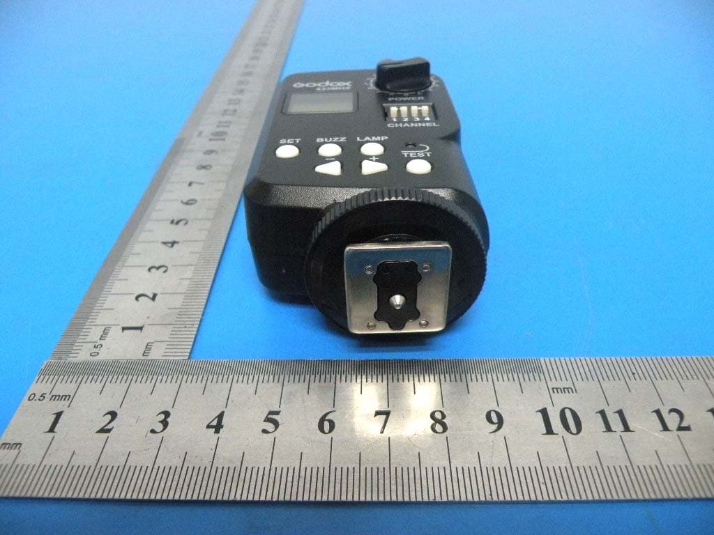
Click to zoom
Application Details
- Equipment Class
- DSC - Part 15 Security/Remote Control Transmitter
- Date of Grant
- Jul 18, 2013
- Application Purpose
- Original Equipment
- Date of Application
- Jul 18, 2013
- Equipment Note
- Power-controlling and triggering remote control
- Frequency Range
- 433.92000000 - 433.92000000
- Country
- China
Documents & Files
Document Text
Text extracted from the exhibit documents filed with the FCC. Open a document above to read the original.
Users Manual
GODOX PHOTO EQUIPMENT CO.LTD Wireless Power-Control Flash Trigger FT-16 Instruction Manual Foreword Thanks for purchasing a Godox product. The wireless power-control flash trigger FT-16 is designed for versatile use. When used on Godox flashes (with wireless control port), it is not only a flash trigger, but also incorporates multiple functions, such as, adjusting power ratio, controlling the on-or-off of the buzzer and the modeling lamp or the AF-assist beam. The trigger set consists of a transmitter (on-camera) and a receiver (on-flash). Contents Foreword For your safety Parts Body Battery ON/OFF Switch Power-Ratio Display Mode Channel Select Switch Power-Control Group Selection Other Buttons Using the Trigger Adjusting Flash Settings Triggering Flash Technical Data Troubleshooting Maintenance For your safety Before using this product, please read the following safety instructions carefully in order to ensure your safety and the proper operation of this product. Keep for future reference. Failure to observe the following precautions marked by could result in product damages. The icon indicates warnings that should be read beforehand to avoid any possible damage or injury. Do not disassemble or modify. Failure to observe this precaution could result in electric shock or product malfunction. Should this product break open due to falling or other accident, take out the batteries and sent it to an authorized maintenance center. Keep dry. Do not handle with wet hands, immerse in water, or expose to rain. Failure to observe this precaution could cause fire or electric shock. Do not use in the presence of flammable gases. Failure to observe this precaution could result in fire or explosion. Keep out of the reach of children. This product contains small parts that may pose a choking hazard. Should a child swallows any part of this product, consult a physician immediately. Turn off the trigger immediately should malfunction occurs. Should smoke or an unusual smell come from this product, take out the batteries immediately in case of burning and send this product to an authorized maintenance center. Continued use may result in injuries. Do not expose to high temperature. Do not leave the product in a closed vehicle in the sun or in other areas subject to extremely high temperature. Failure to observe this precaution could result in fire or damage to the casing or internal parts. Observe precautions when handling batteries. Batteries may leak or explode if improperly handled. Please observe the following precautions when handling batteries for this product: ----Use only batteries listed in this manual. Do not mix new and old batteries. Neither use batteries of different brands. ----Read and following all warnings and instructions provided by the battery manufacturer. ----Batteries cannot be short-circuited or disassembled. ----Do not put batteries into a fire or apply direct heat to it. ----Do not attempt to install batteries in the reverse direction. ----Batteries are prone to leak when fully discharged. To avoid damage to the product, be sure to take out the batteries if the product will not be used for an extended period or the battery power is empty. ----Should liquid from damaged batteries come into contact with skin or clothing, rinse immediately with fresh water. Parts Body 01. ON/OFF Switch ----Power on (ON) ----Power off (OFF) 02. LCD display 03. Power-Control Group Select Dial (POWER) 04. Channel Select Switch (CHANNEL) 05. Set Button (SET) 06. Buzz Switch (BUZZ) 07. Modeling Lamp (LAMP) AF-assist Beam Switch 08. Test Button (TEST) 09. <-> Button 10. <+> Button 11. Hot shoe 12. Indicator 13. Antenna 14. Battery Compartment 15. Wireless Control Plug Transmitter FT-16 Receiver FTR-16 Battery The transmitter needs two size-AA batteries (not provided). The receiver draws power from a flash through the flash’s Wireless Control Port. Slide the battery compartment cover of the transmitter and insert the batteries as shown in the illustration. Note: Low Battery Indication When the battery power (<2.2V) gets low, is shown on the LCD display. Please change batteries as low battery power leads to no flash or flash missing in case of long distance. Power Switch Turn the transmitter on by sliding the ON/OFF Switch to ON. The LCD display will then light up. Note: Turn the transmitter off to save power if it will not be used for an extended period. Power-Ratio Display Mode The trigger set has two modes to display a flash’s power ratio. 1. 1/128~1/1: widely adopted in most shoe mount flashes. 2. 5.0~10: widely adopted in most studio flashes. The two display modes can be switched over by pressing and the Set Button and holding for 2s. Channel Select Switch The trigger set provides 16 channels for communication. Set the transmitter and the receiver to the same channel before use. Check the following table for channel settings: Channel 1 2 3 4 5 6 7 8 9 10 11 12 13 14 15 16 S1 0 1 0 1 0 1 0 1 0 1 0 1 0 1 0 1 S2 0 0 1 1 0 0 1 1 0 0 1 1 0 0 1 1 S3 0 0 0 0 1 1 1 1 0 0 0 0 1 1 1 1 S4 0 0 0 0 0 0 0 0 1 1 1 1 1 1 1 1 Note: The transmitter and the receiver must be set to the same channel for wireless control. Otherwise, the receiver does not response. Power-Control Group Selection Both the transmitter and the receiver have a 16-grade Power-Control Group Select Dial (hereinafter referred to as Dial). With these 16 grades, you can wireless control at most 16 flash groups in terms of the following functions: adjusting the power ratios and turning on/off the buzzer and the modeling lamp or the AF-assist beam. Attach the receiver(s) on multiple flashes/one flash and set the Dial of each receiver to the same grade. This is a flash group. Then attach the transmitter on the camera’s hotshoe or hold it in hand, and set the Dial to the same grade as that of receiver(s). After settings, the flashes will be under your command. Note: 1. The Dial of the transmitter and the receiver must be set to the same grade. Otherwise, th…
Text truncated - open the document above for the full version.
Cover Letter(s)
GODOX PHOTO EQUIPMENT CO. LTD Date: 16.07.2013 Authority to Act as an Agent We declare that the following representative (agent) Name Mark Zhu Position Manager Company Name Shenzhen Certification Technology Service Co., Ltd. Address 2F, Building B, East Area of Nanchang Second Industrial Zone, Gushu 2 nd Road, Bao’an District, Shenzhen 518126, P.R. China Tel / Fax 0755-86375541/0755-26736857 Email [email protected] to act on our behalf on all matters concerning the application and documents submitted to PHOENIX TEST-LAB for product certification below Product Name Power-controlling and triggering remote control Model Name FT-16 Brand Name N/A . Yours sincerely, Signatory Name Justin Chen Position Manager Company Name GODOX PHOTO EQUIPMENT CO. LTD Address 25th Floor, Building Jinfeng Cheng Block B, 5015 Shennan East Road, Luohu District, Shenzhen Tel +86-755-25737526 Fax +86-755-29596412 Email [email protected] In case of FCC, we certify that we are not subject to a denial of Federal benefits, that include FCC benefits, pursuant to Section 5301 of the Anti-Drug Abuse Act of 1988, 21 U.S.C. §862 because of a conviction for possession or distribution of a controlled substance.
Cover Letter(s)
GODOX PHOTO EQUIPMENT CO. LTD Federal Communications Commission Equipment Authorization Branch 7435 Oakland Mills Road Columbia, MD 21046 Request for Confidentiality Company name: GODOX PHOTO EQUIPMENT CO. LTD FCC ID : 2AAJJFT-16 FCC Part 15 Certification Gentlemen, Pursuant to 47 CFR 0.457(d)(1)(ii) and 0.459 we hereby requests permanent confidentiality of the following documents for the subject application: Exhibit Type Description ☒ Schematics All circuitry of devices and component values ☒ Block Diagrams Details of device showing the frequency of all oscillators ☒ Operational Description Description of the circuit functions Note: Exhibit types that are commonly held confidential are: (1) Schematics, (2) Block Diagrams, (3) Bill Of Materials, (4) Operational Descriptions. Any exhibit NOT granted confidentiality is viewable on the FCC website as soon as a grant is issued. These documents contain detailed system and equipment description and related information about the product which we considers to be proprietary, confidential and a custom design and otherwise would not release to the general public. Since the design is a basis from which future technological products will evolve, we consider that this information would be of benefit to its competitors and that the disclosure of the information in these documents would give competitors an unfair advantage in the market. Yours sincerely, Signatory Name Justin Chen Position Manager Company Name GODOX PHOTO EQUIPMENT CO. LTD Address 25th Floor, Building Jinfeng Cheng Block B, 5015 Shennan East Road, Luohu District, Shenzhen Tel +86-755-25737526 Fax +86-755-29596412 Email [email protected]
ID Label/Location Info
30mm 16mm FCC ID: 2AAJJFT-16 This device complies with Part 15 of the FCC Rules. Operation is subject to the following two conditions: (1) this device may not cause harmful interference, and (2) this device must accept any interference received, including interference that may cause undesired operation.
ID Label/Location Info
Label Location
Internal Photos
ANTENNA ANTENNA
Test Report
Shenzhen Certification Technology Service Co., Ltd 2F, Building B, East Area of Nanchang Second Industrial Zone, Gushu 2nd Road, Bao'an District, Shenzhen 518126, P.R. China. FCC ID: 2AAJJFT-16 Page 1 of 30 TEST REPORT FCC ID: 2AAJJFT-16 Applicant : GODOX PHOTO EQUIPMENT CO. LTD Address : 25th Floor, Buildin g Jinfeng Cheng Block B, 5015 Shennan East Road, Luohu District, Shenzhen, China. Equipment under Test (EUT): Name : Power-controlling and triggering remote control Model : FT-16 Standards : FCC PART 15, SUBPART C : 2012 (Section 15.231) Report No. : STI130621091 Date of Test : July 2-16, 2013 Date of Issue : July 17, 2013 Test Result : PASS * * In the configuration tested, the EUT complied with the standards specified above Authorized Signature (Mark Zhu) General Manager The manufacture should ensure that all the products in series production are in conformity with the product sample detailed in this report. If the product in this report is used in any configuration other than that detailed in the report, the manufacturer must ensure the new system complies with all relevant standards. Any mention of Shenzhen Certification Technology Service Co., Ltd. Or test done by Shenzhen Certification Technology Service Co., Ltd. Approvals in connection with, distribution or use of the product described in this report must be approved by Shenzhen Certification Technology Service Co., Ltd. Approvals in writing. Report No.: STI130621091 FCC ID: 2AAJJFT-16 Page 2 of 30 TABLE OF CONTENT Description Page 1 General Information ---------------------------------------------------------------------------------- 3 1.1 Description of Device (EUT)---------------------------------------------------------------------3 1.2 Description of Test Facility -----------------------------------------------------------------------3 2 EMC Equipment List --------------------------------------------------------------------------------- 4 3 Test Procedure----------------------------------------------------------------------------------------- 5 4 Summary of Measurement ------------------------------------------------------------------------- 6 4.1 Summary of test result ----------------------------------------------------------------------------6 4.2 Block Diagram -------------------------------------------------------------------------------------6 4.3 Assistant equipment used for test ----------------------------------------------------------------6 4.4 Test Conditions -------------------------------------------------------------------------------------7 4.5 Measurement Uncertainty (95% confidence levels, k=2)-------------------------------------7 5 Radiation Emission----------------------------------------------------------------------------------- 8 5.1 Radiation Emission Limits(15.209&231)-------------------------------------------------------8 5.2 Test Setup -------------------------------------------------------------------------------------------8 5.3 Test Procedure------------------------------------------------------------------------------------ 10 5.4 Test Equipment Setting For emission test. --------------------------------------------------- 11 5.5 Test Condition------------------------------------------------------------------------------------ 11 5.6 Test Result ---------------------------------------------------------------------------------------- 11 6 POWER LINE CONDUCTED EMISSION ------------------------------------------------------- 16 6.1 Conducted Emission Limits(15.209) ---------------------------------------------------------- 16 6.2 Test Setup ----------------------------------------------------------------------------------------- 16 6.3 Test Procedure------------------------------------------------------------------------------------ 17 6.4 Test Results --------------------------------------------------------------------------------------- 17 7 Occupied bandwidth -------------------------------------------------------------------------------- 18 7.1 Test limit ------------------------------------------------------------------------------------------ 18 7.2 Method of measurement ------------------------------------------------------------------------ 18 7.3 Test Setup ----------------------------------------------------------------------------------------- 18 7.4 Test Results --------------------------------------------------------------------------------------- 18 8 Transmission time ----------------------------------------------------------------------------------- 20 8.1 Test limit ------------------------------------------------------------------------------------------ 20 8.2 Method of measurement ------------------------------------------------------------------------ 20 8.3 Test Setup ----------------------------------------------------------------------------------------- 20 8.4 Test Results --------------------------------------------------------------------------------------- 20 9 Band Edge Check------------------------------------------------------------------------------------ 22 9.1 Test limit ------------------------------------------------------------------------------------------ 22 9.2 Test Procedure------------------------------------------------------------------------------------ 22 9.3 Test Setup ----------------------------------------------------------------------------------------- 22 9.4 Test Result ---------------------------------------------------------------------------------------- 22 10 Antenna Requirement ------------------------------------------------------------------------------ 23 10.1 Standard Requirement --------------------------------------------------------------------------- 23 10.2 Antenna Connected Construction-------------------------------------------------------------- 23 10.3 Result ---------------------------------------------------------------------------------------------- 23 11 Photographs of Test Setup ---------------------------------------…
Text truncated - open the document above for the full version.
Test Setup Photos
Radiated Emission Test Setup in Chamber
Contact Information
Applicant
Justin Chen(Manager)
Test Firm
Shenzhen Certification Technology Service Co., LtdMark Zhu
Technical Specifications
| # | Rule Parts | Frequency Range | Power Output |
|---|---|---|---|
| 1 | 15.231 | 433.92 MHz - 433.92 MHz | - |