2AAJSAK2Microwave Motion Detector
GUGLIELMI SNC DI GUGLIELMI GUGLIELMO E C.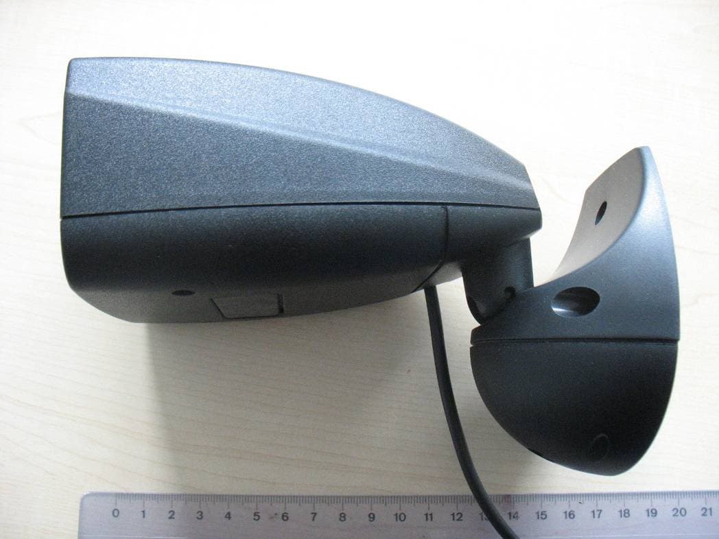
Click to zoom
Application Details
- Equipment Class
- FDS - Part 15 Field Disturbance Sensor
- Date of Grant
- Nov 25, 2013
- Application Purpose
- Original Equipment
- Date of Application
- Nov 25, 2013
- Equipment Note
- Microwave Motion Detector
- Frequency Range
- 24075.00000000 - 24175.00000000
- Country
- Italy
Documents & Files
Document Text
Text extracted from the exhibit documents filed with the FCC. Open a document above to read the original.
Users Manual
HAWK2_01MI web: www.guglielmisnc.it Via Cagliari, 19 - Tel. +390112482361 web: www.guglielmisnc.it Via Cagliari, 19 - Tel. +390112482361 e-mail: [email protected] 10153 Torino - ITALY e-mail: [email protected] 10153 Torino - ITALY HAWK 2 DSW3 ON (Normal operation) DSW3 OFF (Positive safety) Tab.2 SETTING OF DETECTION RANGE It is possible to define the controlled area by changing the inclination of the detector and the position of dip-switch 4 (Fig. 3). With trimmer TR1, located on the lower section of the detector (Fig. 1-F), the regulation can be optimised to activate detection only for the desired area. AS: high sensitivity BS: low sensitivity Dimensions in metres Fig. 3 REGULATION OF CONTACT DURATION The trimmer TR2 on the lower section of the detector (Fig. 1-E) can be used to set the desired duration of the electric contact, which can vary from 1 – 6 seconds. Changes or modifications made to this equipment not expressly approved by GUGLIELMI SNC may void the FCC authorization to operate this equipment. HAWK 2 The HAWK 2 microwave movement detector controls the opening of factory gates and automatic doors. It works in the K band. It can be installed at a height ranging from 3 to 6 metres and guarantees the surveillance of an area from 3 to 30 square metres . The device will be automatically activated by moving persons or vehicles within the controlled perimeter. HAWK 2 has been developed using planar technology, and can be set in mono- directional (to detect movement either in forward or backward direction) or bi-directional (activated by movement in both directions). A microprocessor processes the signals received – generated through a Doppler effect – and sends an OK to the opening command. A LED on the front panel indicates that movement has taken place inside the controlled area. TECHNICAL DATA FCC ID: 2AAJSAK2 Power voltage 12 – 24 V AC /12 - 24 V DC Power current max. 40 mA Operative frequency 24,000-24,250 GHz Output Power (EIRP) 20 dBm Range 1 – 10 m adjustable Relay control time 1 – 6 s adjustable Degree of protection IP 65 Installation height max. 6 m Detectable speed 0.1 m/s minimum Relay contact 1A - 24 V AC/DC Vertical directionality 0-60° Horizontal directionality +/- 45° Operating temperature - 20 °C to + 50 °C Dimensions/weight 160x95x110 mm / 500 g Warranty 24 months This device complies with Part 15 of the FCC Rules . Operation is subject to the following two conditions: this device may not cause harmful interference, this device must accept any interference received, including interference that may cause undesired operation. This equipment complies with FCC radiation exposure limits set forth for an uncontrolled environment. This equipment should be installed and operated with minimum distance of 0,66 ft between the radiator and your body. This transmitter must not be co-located or operating in conjunction with any other antenna or transmitter. BS (Incl. 60°) AS (Incl. 45°) HAWK2_01MI web: www.guglielmisnc.it Via Cagliari, 19 - Tel. +390112482361 web: www.guglielmisnc.it Via Cagliari, 19 - Tel. +390112482361 e-mail: [email protected] 10153 Torino - ITALY e-mail: [email protected] 10153 Torino - ITALY HAWK 2 SETTING FOR OPERATION The HAWK 2 movement detector can be configured in mono direction mode (one direction only) or in bi directional mode (in both directions). Remove the rubber plug from the lower section of the detector (Fig. 1-A) and set the required function through the dip-switch (Fig. 1-B), choosing from the possibilities indicated in the table: DSW1 DSW2 DSW4 SENSITIVITY CONDITION OFF - ON Low Movement is detected in both directions OFF - OFF High Movement is detected in both directions ON OFF ON Low Approach to the sensor is detected ON OFF OFF High Approach to the sensor is detected ON ON ON Low Movement away from the sensor is detected ON ON OFF High Movement away from the sensor is detected ASSEMBLY AND ORIENTATION HAWK 2 can be installed at the centre of the door to be controlled or on the side, on non-vibrating structures (walls or ceiling) and at a maximum height of 6 m. Use the template supplied to prepare the holes. Fasten the device using the prepared holes, remove the lower cover (Fig. 2-A) and loosen the screw that blocks the detector orientation. Direct the detector toward the area to be controlled and lock in that position. For correct operation, do not install HAWK 2 : - facing the moving parts of the door - facing fluorescent lights (minimum distance 2m) - facing areas where rain could provoke water fluxes These conditions could activate the device and cause the unwanted opening of the door. ELECTRICAL CONNECTIONS Connect the pre-wired cable as indicated in table 1 then power the detector. HAWK 2 The LED on the detector front panel (Fig. 2-B) will indicate the detection of a movement, for all the time the relay is excited. A E F B B A Fig.1 Fig.2 Tab.1 RELAY CONTACT SETTING HAWK 2 has a relay with switching contact. According to the setting of the dip-switch 3 (Fig. 1-B) in the lower section of the detector, the combinations described in table 2 can be obtained. These conditions are valid when the device is powered. Wire colour Description Red 12-24 V AC/DC Black 12-24 V AC/DC Green COM relay contact Brown NO contact (when device is not powered) Blue NC contact (when device is not powered)
External Photos
Test report no.: 1-6038/13-01-03 2013-10-30 Page 24 of 32 An ne x B E x te rna l ph ot ogra phs o f the E UT Photo 3:
Internal Photos
Test report no.: 1-6038/13-01-03 2013-10-30 Page 25 of 32 An ne x C Inte r na l p ho to gra phs o f the E UT Photo 4: Photo 5: Test report no.: 1-6038/13-01-03 2013-10-30 Page 26 of 32 Photo 6: Photo 7: Test report no.: 1-6038/13-01-03 2013-10-30 Page 27 of 32 Photo 8: Photo 9: Test report no.: 1-6038/13-01-03 2013-10-30 Page 28 of 32 Photo 10: Photo 11: Test report no.: 1-6038/13-01-03 2013-10-30 Page 29 of 32 Photo 12: Photo 13: Test report no.: 1-6038/13-01-03 2013-10-30 Page 30 of 32 Photo 14: Photo 15:
Test Report
2013-10-30 Page 1 of 32 TEST REPORT Test report no.: 1-6038/13-01-03 Testing laboratory Applicant CETECOM ICT Services GmbH Untertuerkheimer Strasse 6 – 10 66117 Saarbruecken / Germany Phone: + 49 681 5 98 - 0 Fax: + 49 681 5 98 - 9075 Internet: http://www.cetecom.com e-mail: [email protected] Accredited Testing Laboratory: The testing laboratory (area of testing) is accredited according to DIN EN ISO/IEC 17025 (2005) by the Deutsche Akkreditierungsstelle GmbH (DAkkS) The accreditation is valid for the scope of testing procedures as stated in the accreditation certificate with the registration number: D-PL-12076-01-01 Area of Testing: Radio/Satellite Communications GUGLIELMI S.n.c. Via Cagliari 19 10153 Torino / ITALY Phone: +39 01 12 48 23 61 Fax: Contact: Flavio Guglielmi e-mail: [email protected] Phone: +39 01 12 48 23 61 Manufacturer GUGLIELMI S.n.c. Via Cagliari 19 10153 Torino / ITALY Test standard/s 47 CFR Part 15 Title 47 of the Code of Federal Regulations; Chapter I Part 15 - Radio frequency devices For further applied test standards please refer to section 3 of this test report. Test Item Kind of test item: Microwave Motion Detector Doppler Model name: HAWK2 FCC ID: 2AAJSAK2 Frequency: 24.075 GHz – 24.175 GHz Antenna: Integrated planar antenna Power Supply: 12 – 24 V AC 12 – 30 V DC from Power Supply Temperature Range: -20°C to +55°C Test report authorised: Test performed: 2013-10-30 Karsten Geraldy 2013-10-30 Meheza Walla Senior Testing Manager Expert Test report no.: 1-6038/13-01-03 2013-10-30 Page 2 of 32 1 Table of contents 1 Table of contents............................................................................................................................................2 2 General information .......................................................................................................................................3 2.1 Notes and disclaimer ..........................................................................................................................3 2.2 Application details...............................................................................................................................3 3 Test standard/s ...............................................................................................................................................3 4 Test environment............................................................................................................................................4 5 Test item ..........................................................................................................................................................4 6 Test laboratories sub-contracted .................................................................................................................4 7 Summary of measurement results ...............................................................................................................5 8 RF measurement testing................................................................................................................................6 8.1 Description of test setup ....................................................................................................................6 8.1.1 Radiated measurements.............................................................................................................6 8.1.2 Additional comments ..................................................................................................................7 9 Measurement results......................................................................................................................................8 9.1 Field strength of emissions (wanted signal) ....................................................................................8 9.2 Occupied bandwidth (99% bandwidth) ...........................................................................................10 9.3 Field strength of emissions (radiated spurious) ............................................................................12 9.4 Conducted spurious emissions < 30 MHz ......................................................................................19 10 Test equipment and ancillaries used for tests ...................................................................................21 11 Observations .........................................................................................................................................22 Annex A Photographs of the test setup ......................................................................................................23 Annex B External photographs of the EUT.................................................................................................24 Annex C Internal photographs of the EUT ..................................................................................................25 Annex D Document history ..........................................................................................................................31 Annex E Further information........................................................................................................................31 Annex F Accreditation Certificate ...............................................................................................................32 Test report no.: 1-6038/13-01-03 2013-10-30 Page 3 of 32 2 General information 2.1 Notes and disclaimer The test results of this test report relate exclusively to the test item specified in this test report. CETECOM ICT Services GmbH does not assume responsibility for any conclusions and generalizations drawn from the test results with regard to other specimens or samples of the type of the equipment represented by the test item. The test report may only be reproduced or published in full. Reproduction or publication of extracts from the report requires the prior written approval of C…
Text truncated - open the document above for the full version.
Test Setup Photos
Test report no.: 1-6038/13-01-03 2013-10-30 Page 23 of 32 An ne x A P ho tog ra phs o f t h e te s t s e tu p Photo 1: Photo 2:
Contact Information
Applicant
FLAVIO GUGLIELMI
Test Firm
cetecom advanced GmbHGerald Schmidt
Technical Specifications
| # | Rule Parts | Frequency Range | Power Output |
|---|---|---|---|
| 1 | 15.245 | 24.07 GHz - 24.18 GHz | - |