2AAK4FCGRANDSuper switch
Zhongshan Grand Enterprise Co.,Ltd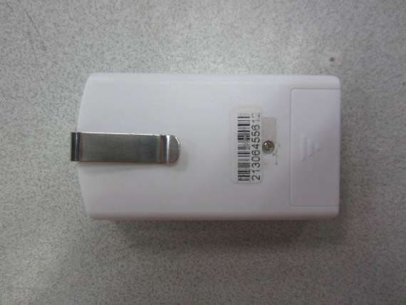
Click to zoom
Application Details
- Equipment Class
- DSC - Part 15 Security/Remote Control Transmitter
- Date of Grant
- Jul 25, 2013
- Application Purpose
- Original Equipment
- Date of Application
- Jul 25, 2013
- Equipment Note
- Super switch
- Frequency Range
- 315.00000000 - 315.00000000
- Country
- China
Documents & Files
Document Text
Text extracted from the exhibit documents filed with the FCC. Open a document above to read the original.
Users Manual
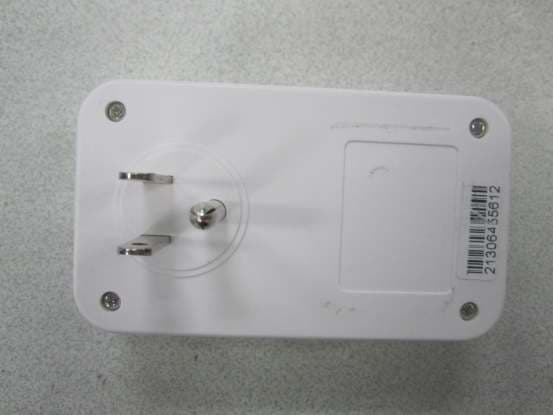
1 The Remote Control for Living Room, Kitchen & Bedroom Lights, Lamps, Fans and More Item/Art. 770742 Model #: SSW2-3-3322 Set of (3) Indoor Outlets and (2) 3- Button Remote Controls Package Includes: (3) Wireless Wall Outlet Receivers (Receiver Units) (2) 3-Button Hand-Held Remote Controls (Sender Units) (2) Type 23A 12V batteries Features: The Super Switch operates on radio frequency and is not dependent on line of sight and will perform through walls, doors and floors up to 60 feet away. No rewiring is required. Hand Held Remote Control: Red Transmit LED Indicator on Hand-Held Remotes lights up when buttons are pressed to confirm ON/OFF send command. Button on Hand-Held Remote Control corresponds to Wall Receiver Units (1, 2, 3). Clip on back of Hand-Held Remote Control is ideal to clip to car sun visor. Never enter a dark home again. Practical and inexpensive peace of mind. Super Switch Indoor Wireless Remote Control Wall Outlets Red LED Indicator Visor Clip 1 2 3 2 Wall Outlet Receivers: NOTE: Wall Outlet Receivers feature 3-prong grounding plugs and are intended for use ONLY in 3-prong INDOOR household AC outlets. DO NOT remove the round grounding prong. If your household AC outlets do not accept 3-prong plugs then consult a qualified electrician to have your household AC outlets upgraded. Red LED Indicators on wall Receiver Units indicate POWER SWITCHED ON at Wall Receiver Unit. Manual POWER ON/OFF Override button on wall Receiver Units allows user to manually turn Wall Receiver Units ON or OFF in the event the Hand-Held Remote cannot be located or if the battery in the Hand-Held Remote fails. Operation: Remove Protective Tape From Battery Chamber. Remove battery cover on Hand-Held Remote Control unit and remove protective tape. To do this: 1) Remove the battery compartment safety screw with a # 3 Phillips screwdriver. 2) Slide the battery compartment cover off. 3) Remove protective tape. 4) Replace battery compartment cover by sliding into place. 5) Reinstall the safety screw. 1. Remove Safety Screw with # 3 Phillips Screw Driver. 2. Slide Battery Cover Out and Off. 3. Remove Protective Tape. 4. Reinstall Battery Cover by sliding back into place 5. Reinstall Safety Screw. Do not over tighten. Red LED Indicator Indicates Power ON Manual ON/OFF Press to turn Power ON, Press to turn Power OFF Grounding Prong - DO NOT REMOVE 3 Plug in Wall Receiver Units. Plug the individual Wall Receiver Unit (s) into any standard 3-prong AC indoor wall outlet. Operation and Safety. Use only 1 Super Switch Wall Receiver Unit per AC outlet. A distance of 24 inches should be maintained between individual Wall Receiver Units. Do not overload individual Super Switch Wall Receiver unit beyond 1000 watts. Maximum output load: 125V/60Hz/10A. FOR INDOOR USE ONLY. DO NOT use Super Switch to control TV ON/OFF Power. Super Switch is not recommended for use with computers and computer monitors. Super Switch is not a circuit overload protector and is not designed or warranted for this purpose. To adequately protect your valuable home electronics, use a commercially available and rated circuit overload protector. Wall Receiver Unit Function. ON/OFF Button (s). The power control button on the front of the wall receiver unit is used to manually power the wall receiver ON when pressed and OFF when pressed again. The unit can also be powered ON with the Hand-Held remote control. The Red LED ON light on the front of the wall receiver unit will illuminate when power is ON. If the Red LED (ON) does not illuminate check to be sure your indoor wall outlet is powered ON (check household circuit breakers, GFI Circuits). Remote Control Functions. The Hand-Held Remote Control unit has a single Red LED indicator light that shows the radio signal has been sent. The Hand- Held Remote Control features three buttons marked 1, 2, and 3 respectively. Each button 1, 2, 3; corresponds to a specific wall receiver unit. Each of the individual receivers is clearly labeled 1, 2 or 3 to correspond to the buttons on the Hand-Held Remote Control unit. Pressing the buttons on the Hand-Held Remote Control turns the power ON or OFF at the corresponding Wall Receiver Unit. NOTE: Do not overload individual Super Switch Wall Receiver unit beyond 1000 watts. Before plugging any appliance into the Super Switch Wall Receiver, review the appliances wattage. If it exceeds 1000 watts, it should not be used with the Super Switch. Maximum output load: 125V/60Hz/10A. Learning Function The Super Switch has the ability to be programmed to control multiple Wall Receiver Units with a single button on a remote control. For example, if you wish to turn all three Wall Receiver Units ON and OFF from button number one on the remote control, do the following: Follow these easy steps: 1. Plug Wall Receiver Units into Indoor AC wall outlets. 2. Press and hold the manual POWER ON/OFF button on the first Wall Receiver Unit you wish to “learn” for 5 seconds. 3. Release the button on the Wall Receiver Unit when the red POWER indicator LED on the Wall Receiver Unit begins blinking. 4. Again, press and hold the manual POWER ON/OFF button on the first Wall Receiver Unit for 5 seconds until the red POWER indicator LED on the Wall Receiver Unit begins blinking. 5. Point the Hand-Held remote control at the Wall Receiver Unit on the wall and press the button on the Hand Held Remote Control (1, 2, or 3) that you want to correspond to the Wall Receiver Unit (s). The red POWER indicator LED on the Hand Held Remote Control flashes once when it has learned the button position that corresponds to the Wall Receiver Unit. 6. Press the manual POWER ON/OFF button on the Wall Receiver Unit one time or wait for 8 seconds to finish the programming process. 7. Repeat this process for each Wall Receiver Unit that you want to be controlled from the same Hand Held Remote control button. 4 Battery Replacement/Storage Replacement: If operation of the wall receiver units becomes erratic, it may be …
Text truncated - open the document above for the full version.
ID Label/Location Info
Product Size: length x width x height: 7.5cm x 4.3cm x 1.5cm Label size: 3.3cm x 0.3cm
Operational Description
1. After press the button, power can be transmitted into device through switch. The device begins to transmit control signal and data signal to recover by wireless through 315MHZ wireless frequency (channel). 2. When receiver received the power-on signal, it activates the external oscillator consisting of oscillation circuits/ chips. Then internal circuit receive the operation and start outputting high voltage signal (relevant high refer to low voltage) to relay to turn on the power of load. (Anything consumes power). 3. The signal will be coded, modeled and transferred out through filters and antenna. 4. When the transmission has been done, the switch signal will become low in order to power off the device and part of its functions.
Test Report
Report No.: 130614076GZU-001 Issued: 22 July 2013 Page 2 of 14 FCC ID: 2AAK4FCGRAND Table of Contents TEST REPORT ........................................................................................................................................................... 1 1 General Description .................................................................................................................................... 3 1.1 Product Description ...................................................................................................................................... 3 1.2 Related Submittal(s) Grants .......................................................................................................................... 3 1.3 Test Methodology ......................................................................................................................................... 3 1.4 Test Facility .................................................................................................................................................. 3 2 System Test Configuration ......................................................................................................................... 4 2.1 Justification ................................................................................................................................................... 4 2.2 EUT Exercising Software ............................................................................................................................. 4 2.3 Special Accessories ....................................................................................................................................... 4 2.4 Equipment Modification ............................................................................................................................... 4 2.5 Measurement Uncertainty ............................................................................................................................. 4 2.6 Support Equipment List and Description ...................................................................................................... 4 3 Radiated Emission Results ......................................................................................................................... 5 3.1 Field Strength Calculation ............................................................................................................................ 5 3.2 Radiated and Spurious Emission Data .......................................................................................................... 6 4 Bandwidth and Timing ............................................................................................................................... 9 4.1 Bandwidth Plot ............................................................................................................................................. 9 4.2 Timing Plot ................................................................................................................................................. 10 4.3 Calculation of Average Factor .................................................................................................................... 10 4.4 Emissions Test Procedures.......................................................................................................................... 13 4.5 Emissions Test Procedures (cont'd) ............................................................................................................ 13 5 Equipment list ........................................................................................................................................... 14 Report No.: 130614076GZU-001 Issued: 22 July 2013 Page 3 of 14 FCC ID: 2AAK4FCGRAND 1 General Description 1.1 Product Description The equipment under test (EUT) is a controller for Wireless Wall Outlet at 315 MHz. The EUT is powered by 12V DC. During normal use, it sends the signal to control the on/off of the Wall Outlet by manual. Antenna Type: wire antenna. 1.2 Related Submittal(s) Grants The FCC ID of corresponding receiver for this transmitter is 2AAK4GRAND. 1.3 Test Methodology Radiated emission measurements were performed according to the procedures in ANSI C63.10 (2009). Radiated Emission measurement was performed in a Semi-anechoic chamber. Preliminary scans were performed in the Semi-anechoic chamber only to determine worst case modes. For each scan, the procedure for maximizing emissions in clause 6.5 & 6.6 of ANSI C63.10 (2009) were followed. All Radiated tests were performed at an antenna to EUT distance of 3 meters unless stated otherwise. 1.4 Test Facility All of the tests are performed at: Keyway Technology Co.,Ltd. located at Baishun Industrial Zone, Zhangmotou Town, Dongguan, Guangdong, China 523638. This test facility and site measurement data have been fully placed on file with the FCC, test firm registration number is 370994. Report No.: 130614076GZU-001 Issued: 22 July 2013 Page 4 of 14 FCC ID: 2AAK4FCGRAND 2 System Test Configuration 2.1 Justification The equipment under test (EUT) was configured for testing in a typical fashion (as a customer would normally use it), and in the confines as outlined in ANSI C63.10 (2009). The EUT was operated standalone and placed in the center of the turntable, which enabled the engineer to maximize emissions through its placement in the three orthogonal axes. For maximizing emission at and above 30 MHz, the EUT was rotated through 360°, the antenna height was varied from 1 meter to 4 meters above the ground plane, and the antenna polarization was changed. This step by step procedure for maximizing emissions led to the data of clause 3.3 in the report. 2.2 EUT Exercising Software There was no special software to exercise the device. 2.3 Special Accessories There are no special accessories necessary for compliance of this product. 2.4 Equipment Modification Any modificati…
Text truncated - open the document above for the full version.
Contact Information
Applicant
Guo Xiu Na(Sales Manager)
Technical Contact
Intertek Testing Services Shenzhen Ltd.Helen Ma
[email protected]86-20-82139664
Block E, No.7-2 Guang Dong Software Science Park, · Guangzhou · China
Non-Technical Contact
Intertek Testing Services Shenzhen Ltd.Helen Ma
[email protected]86-20-82139664
Test Firm
Keyway Technology Co., LtdJade Yang
Technical Specifications
| # | Rule Parts | Frequency Range | Power Output |
|---|---|---|---|
| 1 | 15.231 | 315 MHz - 315 MHz | - |
Other Applications from Zhongshan Grand Enterprise Co.,Ltd
2AAK4GRAND
Jul 25, 2013Super switch
Equipment Class
CYY - Communications Receiver used w/Pt 15 Transmitter