2AAO2MICRODOGMicrodog
dog hunter LLC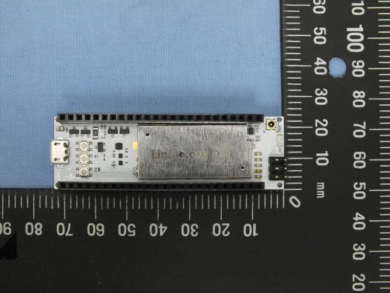
Click to zoom
Application Details
- Equipment Class
- DTS - Digital Transmission System
- Date of Grant
- Feb 17, 2014
- Application Purpose
- Original Equipment
- Date of Application
- Feb 16, 2014
- Equipment Note
- Microdog
- Frequency Range
- 2412.00000000 - 2462.00000000
- Company
- dog hunter LLC
- Country
- United States
Documents & Files
Document Text
Text extracted from the exhibit documents filed with the FCC. Open a document above to read the original.
Users Manual
Microdog Manual Prepared for: Linino SW team Prepared by: Tony Jin( [email protected] ) Friday, January 10, 2014 Brand Name: dog hunter Model Name:DHQDH-W02 Product Name:Microdog Version: V0.2 Revision History Date / Version Name-FunctionNote 7/31/13 / 0.1 FMinitial versioninitial versioninitial versioninitial version 12/25/13 /0.1TJV0.1V0.1V0.1V0.1 01/03/14 /0.2TJV0.2(moified FCC ID and added operation temperature)V0.2(moified FCC ID and added operation temperature)V0.2(moified FCC ID and added operation temperature)V0.2(moified FCC ID and added operation temperature) 01/10/14 /0.2TJV0.2 (modified input current limitation )V0.2 (modified input current limitation )V0.2 (modified input current limitation )V0.2 (modified input current limitation ) dog hunter AG Baarerstrasse 14 6300 Zug Switzerland dog hunter LLC 8 Faneuil Hall Boston, MA 02109 USA T (978) 631-‐0369 dog hunter Inc. ( 多航有限公司 ) 14th Floor, No. 8, Sec. 5, Xinyi Rd Taipei Taiwan 11049 ...........................................................................................HW specification!3 .......................................................................................................................Features!3 ........................................................Summary Linino image!4 ................................................How to build environment and first image !4 ..............................................................Summary GPIO JP1!7 ..............................................................................................Pin definitions !7 ................................................................................How to activate a GPIO!8 ...........................................................How to use AVRDUDE using GPIO!10 .............................................................................Appendix!13 ...................................................................Setting Up An SSH Certificate!13 ......................................................................................Step1: Generating RSA key!13 .............................................................................................Step2: Edit SSH config!13 ......................................................................................Step3: Restart SSH service!14 ..............Federal Communication Commission Interference Statement!15 ...................................................................................................IMPORTANT NOTE:!15 .............................................................USERS MANUAL OF THE END PRODUCT:!15 ..............................................................................LABEL OF THE END PRODUCT:!16 DS3 Manual HW specification AR9331 Highly-Integrated and Cost Effective IEEE 802.11n - 1x1 2.4 GHz SoC for AP and Router Platforms Features ■ Complete IEEE 802.11n 1x1 AP or router in a single chip ■ MIPS 24K processor operating at up to 400 MHz ■ 64MB DDR2 memory ■ 16MB SPI Flash memory ■ External RF connector ■Internal Antenna ■ USB connector /High-speed UART for console support (4.75~ 5.25V/0.5A Input) ■ USB 2.0 host/device mode support ■ GPIO/LED support –with Voltage Level Translator ■ 5V Input (4.75~ 5.25V/1A) ■ Micro SD card support ■Expansion IO compatible with the Arduino Leonardo Temperature • Operating: 0°~60°C • Storage: -10°~70°C Summary Linino image How to build environment and first image The standard build environment for linino images is: Debian squeeze amd64 Using a chroot ́ed environment will also work. This tutorial does not explain how to install Debian or perform sysadmin tasks. Make sure updates and security-updates are enabled and installed. As root (or via sudo): # apt-get update && apt-get upgrade # apt-get install git subversion build-essential python gawk unzip libncurses5-dev libz-dev fastjar asciidoc flex libgtk2.0-dev intltool perl-modules python2.6-dev rsync ruby unzip wget gettext xsltproc tex4ht texlive-lang-french As normal user: ( no root ) Get the source - see https://dev.openwrt.org/wiki/GetSource: any other method is also fine, I prefer git, you might have to adapt the following commands. Once linino branch is created, we will replace the checkout with the official repo. On Ubuntu 12.10 LTS ( quantal ) #sudo apt-get install git subversion build-essential python gawk unzip libncurses5-dev zlib1g-dev fastjar asciidoc flex libgtk2.0-dev intltool perl-modules python-dev rsync ruby unzip wget gettext xsltproc tex4ht texlive-lang-french $ git clone git://nbd.name/openwrt.git $ git clone git://nbd.name/packages.git $ cd openwrt Create the default config and perform a basic check for installed packages required to build: $ make defconfig $ make prereq "make defconfig" will generate linino custom config by default. Customize the build (optional for first time running): $ make menuconfig "make menuconfig" will be unnecesasry in linino branch. Build (use of -j $number_of_cores is highly recommended): $ make build will download and compile everything with defconfig. It takes > 7GB of disk space and a lot of bw/cpu to perform this task. Results will be stored here if build is completed: $ cd bin/ar71xx/ Old way $ git clone git://nbd.name/openwrt.git $ cd openwrt/trunk Download the package feeds and install them: $ ./scripts/feeds update -a $ ./scripts/feeds install -a $ ls *3020* ignore jffs2 images for now. squashfs images come in two forms: factory.bin - to be used for the very first time when switching from factory firmware to openwrt firmware. sysupgrade.bin - to be used to perform upgrades from openwrt to openwrt. Build the documentation: $ make -C docs/ OpenWRT documentation has an incredibly simple HowTO build packages and feeds. I verified that the contents it ́s actually correct and those are the URLs: http://wiki.openwrt.org/doc/devel/packages http://wiki.openwrt.org/doc/devel/feeds#creating.your.own.feed Tons of examples can be found in $ ~/openwrt/root/trunk/feeds$ pwd/home/wrt/openwrt/root/trunk/feeds (base…
Text truncated - open the document above for the full version.
Cover Letter(s)
RF_734_00, Issue 1 Modular Approval Request FCC (per DA 00-1407) FCC ID: 2AAO2MICRODOG Items to be covered Answer from applicant 1. The modular transmitter must have its own RF shielding. The modular has a shielding Case. Please refer to EUT Photo. 2. The modular transmitter must have buffered modulation/data inputs (if such inputs are provided) to ensure that the module will comply with Part 15 requirements under conditions of excessive data rates or over-modulation. The component number is AR9331. 3. The modular transmitter must have its own power supply regulation. The component number is AR9331,RT8010,MMBT2907A 4. The modular transmitter must comply with the antenna requirements of Section 15.203 and 15.204(c). The antenna must either be permanently attached or employ a “unique” antenna coupler (at all connections between the module and the antenna, including the cable).. Antenna is integrated with this module. And no external amplifier will be used with this modular. 5. The modular transmitter must be tested in a stand-alone configuration, i.e., the module must not be inside another device during testing. This is intended to demonstrate that the module is capable of complying with Part 15 emission limits regardless of the device into which it is eventually installed. This modular is tested under stand-alone configuration. Please refer to Test setup photo. 6. The modular transmitter must be labeled with its own FCC ID number, and, if the FCC ID is not visible when the module is installed inside another device, then the outside of the device into which the module is installed must also display a label referring to the enclosed module. This exterior label can use wording such as the following: “Contains Transmitter Module FCC ID: XYZMODEL1” or “Contains FCC ID: XYZMODEL1.” Any similar wording that expresses the same meaning may be used. The Grantee may either provide such a label, an example of which must be included in the application for equipment authorization, or, must provide adequate instructions along with the module which explain this requirement. In the latter case, a copy of these instructions must be included in the application for equipment authorization. The modular transmitter is labelled with its own FCC ID number. Please refer to label sample and label location. 7. The modular transmitter must comply with any specific rule or operating requirements applicable to the transmitter and the manufacturer must provide adequate instructions along with the module to explain any such requirements. A copy of t hese instructions must be included in the application for equipment authorization. For example, there are very strict operational and timing requirements that must be met before a transmitter is authorized for operation under Section 15.231. For instance, data transmission is prohibited, except for operation under Section 15.231(e), in which case there are separate field strength level and timing requirements. Compliance with these requirements must be assured. The modular complies with this requirement. Please refer to user manual. 8. The modular transmitter must comply with any applicable RF exposure requirements. For example, FCC Rules in Sections 2.1091, 2.1093 and specific Sections of Part 15, including 15.319(i), 15.407(f), 15.253(f) and 15.255(g), require that Unlicensed PCS, UNII and millimeter wave devices perform routine environmental evaluation for RF Exposure to demonstrate compliance. In addition, spread spectrum transmitters operating under Section 15.247 are required to address RF Exposure compliance in accordance with Section 15.247(b)(4). Modular transmitters approved under other Sections of Part 15, when necessary, may also need to address certain RF Exposure concerns, typically by providing specific installation and operating instructions for users, installers and other interested parties to ensure compliance. The device complies with this requirement. Please refer to RF exposure report. Note: If compliance with one or more of the numbered requirements, listed above, cannot be demonstrated, it may be possible to obtain a “Limited Modular Approval” (LMA). Name and surname of applicant (or authorized representative): __________________ Date: ___11 February 2014____ Signature: ___________________________
External Photos
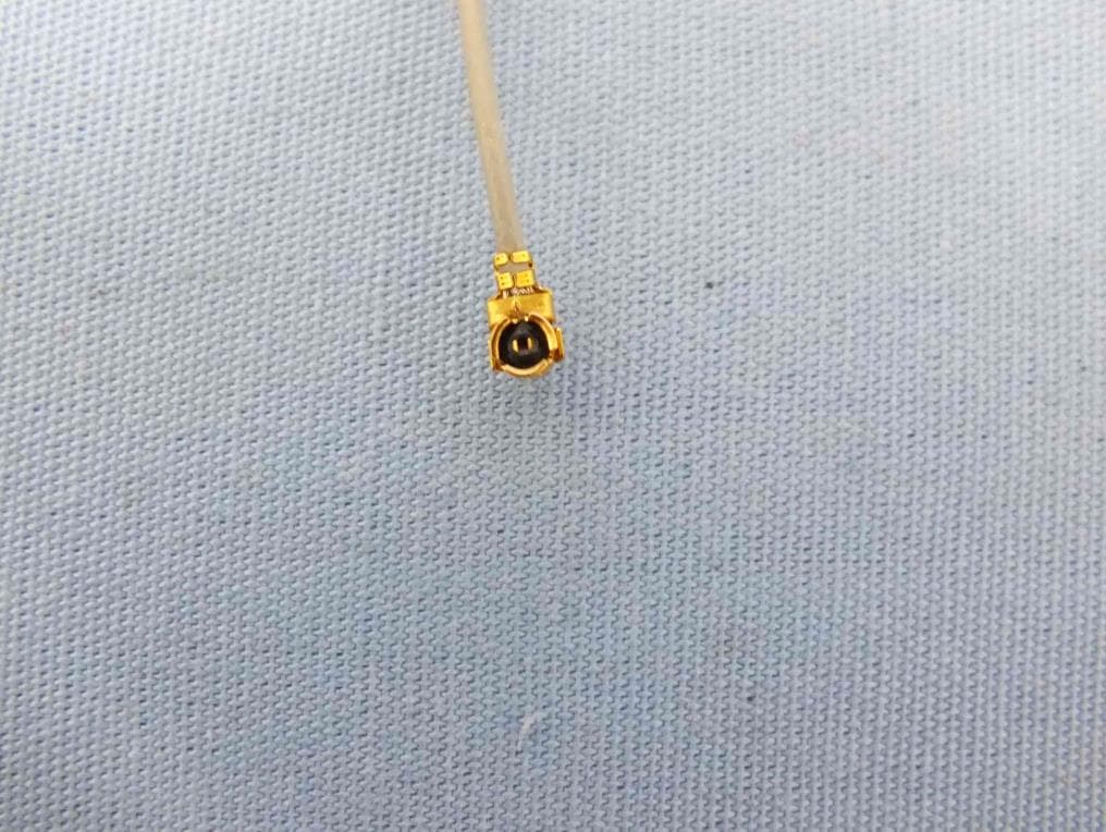
Photographs of EUT Project No.: EP3D0604 Page No. : 1 of 5 Project No.: EP3D0604 Page No. : 2 of 5
ID Label/Location Info
1:1 20 mm 10 mm
Internal Photos
Project No.: EP3D0604 Page No. : 3 of 5 Project No.: EP3D0604 Page No. : 4 of 5 Project No.: EP3D0604 Page No. : 5 of 5
RF Exposure Info
Report No.: FA3D0604 Page : 1 of 4 Report Version: Rev. 01 FCC RF Exposure Report FCC ID : 2AAO2MICRODOG Equipment : Microdog Model No. : DHQDH-W02 Brand Name : dog hunter Applicant : dog hunter LLC Address : 8 Faneuil Hall Boston, MA 02109 USA Standard : 47 CFR FCC Part 2.1091 Received Date : Dec. 06, 2013 Tested Date : Dec. 25, 2013 ~ Jan. 02, 2014 We, International Certification Corp., would like to declare that the tested sample has been evaluated and in compliance with the requirement of the above standards. The test results contained in this report refer exclusively to the product. It may be duplicated completely for legal use with the approval of the applicant. It shall not be reproduced except in full without the written approval of our laboratory. Approved & Reviewed by: Gary Chang / Manager Ty: XXX Report No.: FA3D0604 Page : 2 of 4 Report Version: Rev. 01 Table of Contents 1 MPE EVALUATION OF MOBILE DEVICES ......................................................................................... 4 1.1 LIMITS FOR GENERAL POPULATION/UNCONTROLLED EXPOSURE............................................. 4 1.2 MPE EVALUATION FORMULA ............................................................................................................. 4 1.3 MPE EVALUATION RESULTS .............................................................................................................. 4 Report No.: FA3D0604 Page : 3 of 4 Report Version: Rev. 01 Release Record Report No. Version Description Issued Date FA3D0604 Rev. 01 Initial issue Feb. 05, 2014 Report No.: FA3D0604 Page : 4 of 4 Report Version: Rev. 01 1 MPE EVALUATION OF MOBILE DEVICES Human exposure to RF emissions from mobile devices (47 CFR §2.1091) may be evaluated based on the MPE limits adopted by the FCC for electric and magnetic field strength and/or power density, as appropriate, since exposures are assumed to occur at distances of 20 cm or more from persons. 1.1 LIMITS FOR GENERAL POPULATION/UNCONTROLLED EXPOSURE Frequency Range (MHz) Power Density (mW /cm 2 ) Averaging Time (minutes) 300~1500 F/1500 30 1500~100000 1.0 30 1.2 MPE EVALUATION FORMULA Pd = 2 **4RPi Pt Where Pd= Power density in mW/cm 2 Pt= EIRP in Mw Pi= 3.1416 R= Measurement distance 1.3 MPE EVALUATION RESULTS Frequency Range (MHz) Maximum Conducted Average Power (dBm) Antenna Gain (dBi) Distance (cm) Power Density (mW/cm 2 ) Limit (mW/cm 2 ) 2412~2462 20.07 -0.24 20 0.019 1 ══END══
Test Report
Report No.: FR3D0604 Page : 1 of 59 Report Version: Rev. 01 FCC Test Report FCC ID : 2AAO2MICRODOG Equipment : Microdog Model No. : DHQDH-W02 Brand Name : dog hunter Applicant : dog hunter LLC Address : 8 Faneuil Hall Boston, MA 02109 USA Standard : 47 CFR FCC Part 15.247 Received Date : Dec. 06, 2013 Tested Date : Dec. 25, 2013 ~ Jan. 02, 2014 We, International Certification Corp., would like to declare that the tested sample has been evaluated and in compliance with the requirement of the above standards. The test results contained in this report refer exclusively to the product. It may be duplicated completely for legal use with the approval of the applicant. It shall not be reproduced except in full without the written approval of our laboratory. Approved & Reviewed by: Gary Chang / Manager Ty: XXX Report No.: FR3D0604 Page : 2 of 59 Report Version: Rev. 01 Table of Contents 1 GENERAL DESCRIPTION .................................................................................................................... 5 1.1 Information .............................................................................................................................................. 5 1.2 Local Support Equipment List ................................................................................................................ 8 1.3 Test Setup Chart .................................................................................................................................... 8 1.4 The Equipment List ................................................................................................................................ 9 1.5 Test Standards ..................................................................................................................................... 10 1.6 Measurement Uncertainty .................................................................................................................... 10 2 TEST CONFIGURATION ..................................................................................................................... 11 2.1 Testing Condition ................................................................................................................................. 11 2.2 The Worst Test Modes and Channel Details ....................................................................................... 11 3 TRANSMITTER TEST RESULTS ........................................................................................................ 12 3.1 Conducted Emissions ........................................................................................................................... 12 3.2 6dB and Occupied Bandwidth .............................................................................................................. 15 3.3 RF Output Power .................................................................................................................................. 18 3.4 Power Spectral Density ........................................................................................................................ 20 3.5 Unwanted Emissions into Restricted Frequency Bands ...................................................................... 22 3.6 Emissions in Non-Restricted Frequency Bands ................................................................................... 50 4 TEST LABORATORY INFORMATION ............................................................................................... 59 Report No.: FR3D0604 Page : 3 of 59 Report Version: Rev. 01 Release Record Report No. Version Description Issued Date FR3D0604 Rev. 01 Initial issue Feb. 05, 2014 Report No.: FR3D0604 Page : 4 of 59 Report Version: Rev. 01 Summary of Test Results FCC Rules Test Items Measured Result 15.207 Conducted Emissions [dBuV]: 0.157MHz 51.60 (Margin -14.00dB) - QP Pass 15.247(d) 15.209 Radiated Emissions [dBuV/m at 3m]: 2483.50MHz 73.00 (Margin -1.00dB) - PK Pass 15.247(b)(3) Fundamental Emission Output Power Power [dBm]: 11b: 16.52 11g: 23.59 HT20: 23.59 HT40: 21.27 Pass 15.247(a)(2) 6dB Bandwidth Meet the requirement of limit Pass 15.247(e) Power Spectral Density Meet the requirement of limit Pass 15.203 Antenna Requirement Meet the requirement of limit Pass Report No.: FR3D0604 Page : 5 of 59 Report Version: Rev. 01 1 General Description 1.1 Information 1.1.1 Specification of the Equipment under Test (EUT) RF General Information Frequency Range (MHz) IEEE Std. 802.11 Ch. Freq. (MHz) Channel Number Transmit Chains (N TX ) Data Rate / MCS 2400-2483.5 b 2412-2462 1-11 [11] 1 1-11 Mbps 2400-2483.5 g 2412-2462 1-11 [11] 1 6-54 Mbps 2400-2483.5 n (HT20) 2412-2462 1-11 [11] 1 MCS 0-7 2400-2483.5 n (HT40) 2422-2452 3-9 [7] 1 MCS 0-7 Note 1: RF output power specifies that Maximum Peak Conducted Output Power. Note 2: 802.11b uses a combination of DSSS-DBPSK, DQPSK, CCK modulation. Note 3: 802.11g/n uses a combination of OFDM-BPSK, QPSK, 6QAM, 64QAM modulation. 1.1.2 Antenna Details Ant. No. Model Type Gain (dBi) Connector Remark 1 AA055 Chip -0.24 N/A --- 1.1.3 EUT Operational Condition Power Supply Type 5Vdc from host 1.1.4 Accessories N/A Report No.: FR3D0604 Page : 6 of 59 Report Version: Rev. 01 1.1.5 Channel List Frequency band (MHz) 2400~2483.5 802.11 b / g / n HT20 802.11n HT40 Channel Frequency(MHz) Channel Frequency(MHz) 1 2412 3 2422 2 2417 4 2427 3 2422 5 2432 4 2427 6 2437 5 2432 7 2442 6 2437 8 2447 7 2442 9 2452 8 2447 --- --- 9 2452 --- --- 10 2457 --- --- 11 2462 --- --- 1.1.6 Test Tool and Duty Cycle Test Tool ART2-GUI, Version: 2.3 Duty Cycle and Duty Factor Mode Duty cycle (%) Duty factor (dB) 11b 99.88% 0.01 11g 98.26% 0.08 HT20 98.13% 0.08 HT40 97.37% 0.12 Report No.: FR3D0604 Page : 7 of 59 Report Version: Rev. 01 1.1.7 Power Setting Modulation Mode Test Frequency (MHz) Power Set 11b 2412 0 11b 2437 0 11b 2462 0 11g 2412 0 11g 2437 0 11g 2462 0 HT20 2412 0 HT20 2437 0 HT20 2462 0 HT40 2422 0 HT40 2437 0 HT40 2452 0 Report No.: FR3D06…
Text truncated - open the document above for the full version.
Test Setup Photos
Report No.: FR3D0604 Page: : 1 of 2 Report Version: Rev. 01 Photographs of the Test Configuration Conducted Emission Test Report No.: FR3D0604 Page: : 2 of 2 Report Version: Rev. 01 Radiated Emission Test
Contact Information
Applicant
Tony Jin
Technical Contact
International Certification Corp.Gary Chang
886-3-271-8628
Taiwan
Non-Technical Contact
International Certification Corp.Wendy Liao
886-3-271-8628
Test Firm
International Certification Corp.Jeff Chuang
Technical Specifications
| # | Rule Parts | Frequency Range | Power Output |
|---|---|---|---|
| 1 | 15C | 2.41 GHz - 2.46 GHz | 230.00 mW |
Other Applications from dog hunter LLC
2AAO2CHIWAWA
May 14, 2014Chiwawa
Equipment Class
DTS - Digital Transmission System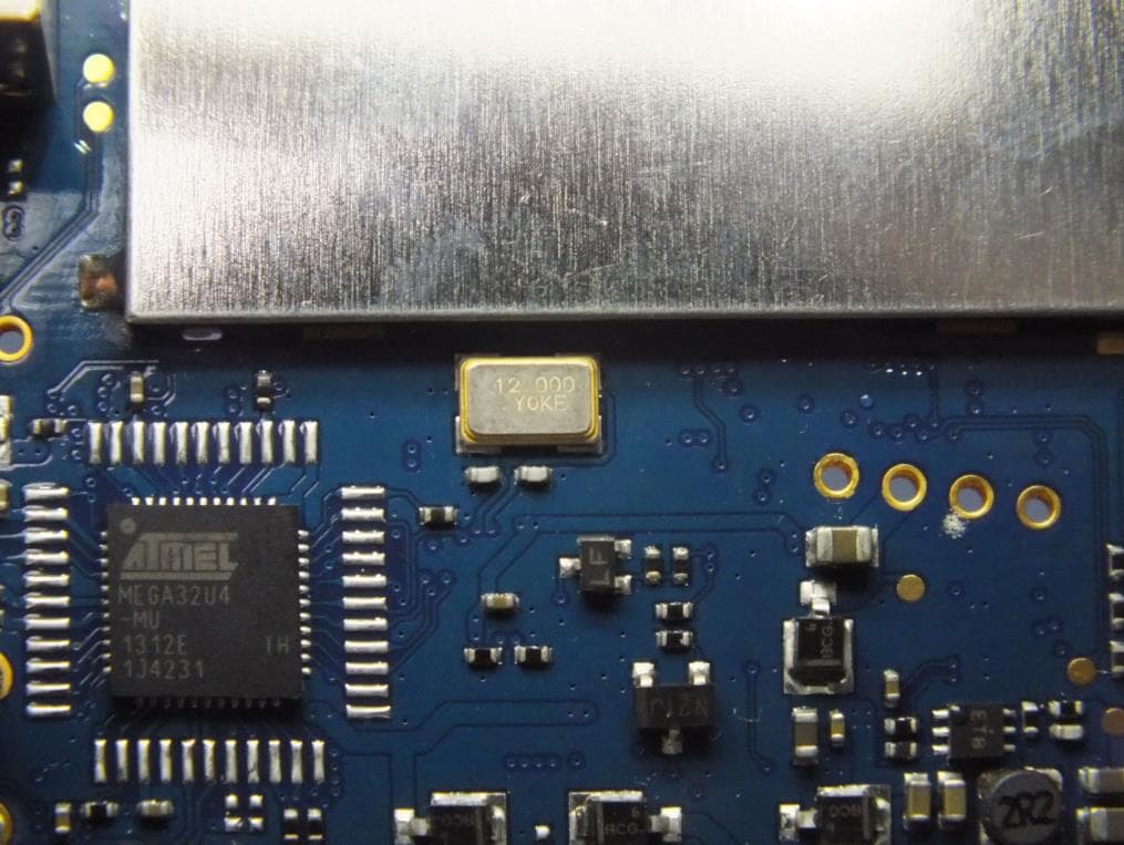
2AAO2DOGSTICK
Aug 11, 2013dogStick
Equipment Class
DTS - Digital Transmission System