2AAP8SPARK40ADIGuitar Speaker
Guoguang Electric Co.,Ltd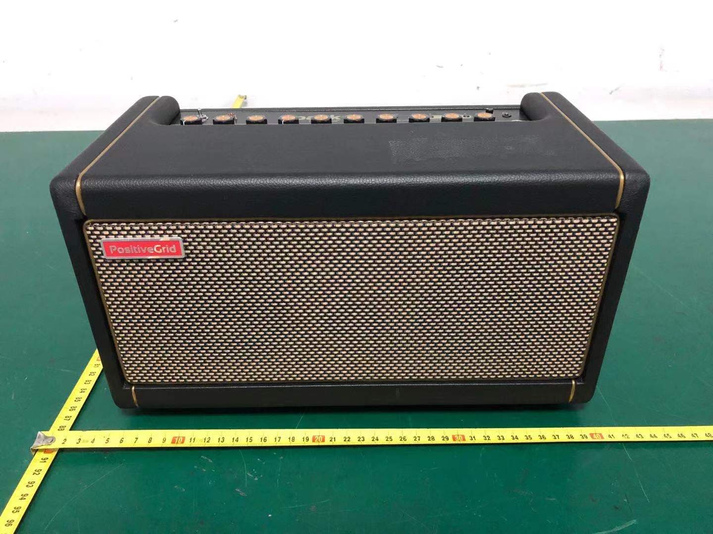
Click to zoom
Application Details
- Equipment Class
- DSS - Part 15 Spread Spectrum Transmitter
- Date of Grant
- Apr 15, 2021
- Application Purpose
- Original Equipment
- Date of Application
- Apr 15, 2021
- Equipment Note
- Guitar Speaker
- Frequency Range
- 2402.00000000 - 2480.00000000
- Company
- Guoguang Electric Co.,Ltd
- Country
- China
Documents & Files
Document Text
Text extracted from the exhibit documents filed with the FCC. Open a document above to read the original.
Users Manual
[PROD Guitar a [PROD FREQ U MAXIM CABIN E POWER SPEAK TOTAL MAINS MAINS WIRE D 1/4" Gu 1/8" Au 1/8" H e WIREL Blueto o UCT DES C amplifier wit UCT SPEC UENCY RAN UM SOUND ET PRINCIP R AMPLIFIE KERS: Two IMPEDAN C INPUT VO FREQUE N D CONNECT uitar Input x Input eadphone ESS CON N oth Audio CRIPTION] th digital au C] NGE: 20-20 D PRESSU PLE: Bass- ERS: 40 Wa - 4" Custom CE: 4 ohms LTAGE: 10 NCY: 50/60 TIVITY NECTIVITY Spark udio process 0,000 Hz URE LEVEL reflex att Class D m Designed s 00 - 240 V Hz k 40 amp sing : 116 dB S P Amplifier Speakers p Manual PL @1m l [TOP C (A) Po w (B) Ta p - - (C) Pre - (D) Adj u (E) He a - (F) Am p - - (G) Am - (H) Eff e - - CONTROL P wer Switch p / Tuner Long pres s Preset LED mode. The The tempo set Switch e Tap to sele when a pre ust the volu adphone Po Main speak p Type Changes t h Use the SP p Control Controls th ects Control Adjusts the Use the SP PANEL] s the button Ds indicate t guitar signa of the dela es ect one of th eset is modi ume from Bl ort ker sound is he amp mod PARK CON e gain, EQ l e amount of PARK CON to engage the pitch be al becomes y effect can he 4 presets fied. Long p uetooth aud s muted wh del in the cu TROL app and volum e Modulation TROL app TUNER mo eing played. s muted whe n be set by t s stored on press the sw dio, Aux in, en a conn e urrent prese to access a e of the am n, Delay and to change t ode. While i . Long press en TUNER tapping (mo the Spark 4 witch again or USB au d ector is inse et. amp models p model in t d Reverb in the effects t n TUNER m s the button mode is en ore than twi 40 amp. The to overwrite dio playbac rted into thi s not selecta the current the curren t type and de mode, the T n again to e ngaged. ice) on the s e red LED f e the prese ck. s port. able by this preset. t preset. etailed effec TAP and 4 exit TUNER switch. flashes t. s switch. cts settings. (I) Out p - (J) Gui t [REAR (K) Blu e - (L) Aux - (M) US - (N) DC - put Adjusts the tar Input PANEL] etooth Statu Indicates th - Con - Wai - Disa In Connect th Bluetooth a B Port Use the su p recording o In Connects t h other AC ad e overall vol us Indicator he status of nnected (blu iting to conn abled (LED e analog o u audio are di pplied USB or firmware he supplied dapter may ume of you r f your Blueto ue light) nect (flashe off) utput of an a sabled whe cable to co updates. d power ada y cause mal r guitar. ooth audio c es) audio devic en a connec onnect your apter. Only functions. connection: ce to this po ctor is insert r computer t use the spe : ort. USB aud ted into this to the Spark ecified AC a dio playbac s port. k amp for U adapter. Usi k and USB ing any [USING SPARK 40 AS A WIRELESS SPEAKER] - Turn on the Bluetooth function on your device, and then select “Spark 40 Audio” from the list of available options. - Spark 40 automatically pairs with previously connected devices when turned on. It can also be paired with other devices (for example, if a previously connected device is not available). - To reset pairing, turn on Spark 40 while holding down preset button 4 for 3 seconds. FCC STATEMENT 1. This device complies with Part 15 of the FCC Rules. Operation is subject to the following two conditions: (1) This device may not cause harmful interference, and (2) This device must accept any interference received, including interference that may cause undesired operation. 2. Changes or modifications not expressly approved by the party responsible for compliance could void the user's authority to operate the equipment. NOTE: This equipment has been tested and found to comply with the limits for a Class B digital device, pursuant to Part 15 of the FCC Rules. These limits are designed to provide reasonable protection against harmful interference in a residential installation. This equipment generates uses and can radiate radio frequency energy and, if not installed and used in accordance with the instructions, may cause harmful interference to radio communications. However, there is no guarantee that interference will not occur in a particular installation. If this equipment does cause harmful interference to radio or television reception, which can be determined by turning the equipment off and on, the user is encouraged to try to correct the interference by one or more of the following measures: Reorient or relocate the receiving antenna. Increase the separation between the equipment and receiver. Connect the equipment into an outlet on a circuit different from that to which the receiver is connected. Consult the dealer or an experienced radio/TV technician for help. This device contains licence-exempt transmitter(s)/receiver(s) that comply with Innovation, Science and Economic Development Canada’s licence-exempt RSS(s).Operation is subject to the following two conditions: (1) This device may not cause interference, and (2) this device must accept any interference, including interference that may cause undesired operation of the device. Cet appareil contient des émetteurs / récepteurs exemptés de licence conformes aux RSS (RSS) d'Innovation, Sciences et Développement économique Canada. L'exploitation est autorisée aux deux conditions suivantes : (1) l'appareil nedoit pas produire de brouillage, et (2) l'utilisateur de l'appareil doit accepter tout brouillage radioélectrique subi, même si le brouillage est susceptible d'en compromettre le fonctionnement. This class [B] digital apparatus complies with Canadian ICES-003. CAN ICES-3 (B) / NMB-3 (B) Ce produit de classe [B] est conforme aux spécifications de la réglementation ICES-003 du Canada. CAN ICES-3 (B) / NMB-3 (B) Caution: FCC/IC Radiation Exposure Statement This equipment complies with FCC/IC RSS-102 radiation exposure limits set forth for an uncontrolled environment. This equipment should be installed and operated with a minimum distance of 20cm between the radiator and any part of your body. Pour se conformer aux exigences de conformité CNR 102 RF exposition, une distance de séparation d'au m…
Text truncated - open the document above for the full version.
Cover Letter(s)
DATE Fed e Auth 7345 Colu On o Sant this des c each Com appr For i beha for c Road <Sig n Name Title: Applic : 2021/3/10 eral Commu horization & 5 Oakland M umbia, Mary our behalf, tun, Houjie, application cribe the dev h unit manuf mmission’s r roval with th instances w alf, I acknow certification, d, Xinhua St nature> e:Alan Son N/A cant Compa 0 unications C Evaluation D Mills Road land 21046 I appoint E Dongguan, for equipm vice or syste factured, im regulations is applicati o where our au wledge that still resides treet, Huadu ng any:Guogu ommission Division Author i EST Techno Guangdon ment certifica em for which ported or m will have a on. uthorized ag all responsi with Guog u Reg, Guan uang Electr ity to Act as ology Co., g, China to ation. I cert h equipment arketed, as affixed to it ent signs t h ibility for com guang Electr ngzhou, Chin ric Co.,Ltd s Agent Ltd. Addre o act as our tify that sub t certification defined in t a label ide he applicatio mplying with ic Co.,Ltd na ess:Chilingxi r agent in th bmitted doc n is sought. he Federal entical to th on for certific h the terms Address:N iang, Qisha he preparati cuments pro I also certify Communica hat submitte cation on ou and conditio No.8 Jinghu antou, on of operly y that ations ed for ur ons
Cover Letter(s)
DATE : 2021-03-10 Equipment Autorisation Division Federal Communications Commission 7435 Oakland Mills Road Columbia, MD 21046 FCC ID: 2AAP8SPARK40ADI Product Name: Guitar Speaker Request for Confidentiality Pursuant to Sections 0.457 and 0.459 of the commissions rules, we hereby request that the following documents be held confidential: Schematics Block diagram Operation description These materials contain trade secrets and proprietary information and are not customarily released to the public. The public disclosure of this information might be harmful to the company and provide unjustified benefits to our competitors. <Signature> Name:Alan Song Title:N/A Company:Guoguang Electric Co.,Ltd
External Photos
External Photos M/N: Spark 40 External Photos M/N: Spark 40 External Photos M/N: Spark 40 External Photos M/N: Spark 40 External Photos M/N: Spark 40 External Photos M/N: Spark 40
ID Label/Location Info
Label Location
Internal Photos
Internal Photos M/N: Spark 40 Internal Photos M/N: Spark 40 Bluetooth Antenna Internal Photos M/N: Spark 40 Internal Photos M/N: Spark 40 Bluetooth Antenna Connector Internal Photos M/N: Spark 40 Internal Photos M/N: Spark 40
RF Exposure Info
FCC ID: 2AAP8SPARK40ADI EST Technology Co. ,Ltd Report No. ESTE-R2103033 Page 1 of 4 FCC 47 CFR MPE REPORT Guoguang Electric Co.,Ltd Guitar Speaker Model Number: Spark 40 FCC ID: 2AAP8SPARK40ADI Prepared for: Guoguang Electric Co.,Ltd No.8 Jinghu Road, Xinhua Street, Huadu Reg, Guangzhou, China Prepared By: EST Technology Co., Ltd. Chilingxiang, Qishantou, Santun, Houjie, Dongguan, Guangdong, China Tel: 86-769-83081888-808 Report Number: ESTE-R2103033 Date of Test: Jan. 30~Mar. 03, 2021 Date of Report: Mar. 05, 2021 FCC ID: 2AAP8SPARK40ADI EST Technology Co. ,Ltd Report No. ESTE-R2103033 Page 2 of 4 Maximum Permissible Exposure 1. Applicable Standards Systems operating under the provisions of this section shall be operated in a manner that ensures that the public is not exposed to radio frequency energy level in excess limit for maximum permissible exposure. In accordance with 47 CFR FCC Part 2 Subpart J, section 2.1091 this device has been defined as a mobile device whereby a distance of 0.2m normally can be maintained between the user and the device. 1.1. Limits for Maximum Permissible Exposure (MPE) (a) Limits for Occupational/Controlled Exposure Frequency Range (MHz) Electric Field Strength (E) (V/m) Magnetic Field Strength (H) (A/m) Power Density (S) (mW/cm 2 ) Averaging Times ︱E︱ 2 ,︱H︱ 2 or S (minutes) 0.3-3.0 614 1.63 (100)* 6 3.0-30 1842/f 4.89/f (900/f)* 6 30-300 61.4 0.163 1.0 6 300-1500 F/300 6 1500-10000 5 6 (b) Limits for General Population / Uncontrolled Exposure Frequency Range (MHz) Electric Field Strength (E) (V/m) Magnetic Field Strength (H) (A/m) Power Density (S) (mW/cm 2 ) Averaging Times ︱E︱ 2 ,︱H︱ 2 or S (minutes) 0.3-1.34 614 1.63 (100)* 30 1.34-30 824/f 2.19/f (180/f)* 30 30-300 27.5 0.073 0.2 30 300-1500 F/1500 30 1500-10000 1.o 30 Note: f=frequency in MHz; *Plane-wave equivalent power density FCC ID: 2AAP8SPARK40ADI EST Technology Co. ,Ltd Report No. ESTE-R2103033 Page 3 of 4 1.2. MPE Calculation Method E (V/m) = d G×P×30 Power Density: Pd (W/m 2 ) = 377 E 2 E = Electric Field (V/m) P = Peak RF output Power (W) G = EUT Antenna numeric gain (numeric) d = Separation distance between radiator and human body (m) The formula can be changed to Pd = 2 d×377 G×P×30 From the peak EUT RF output power, the minimum mobile separation distance, d=0.2m, as well as the gain of the used antenna, the RF power density can be obtained FCC ID: 2AAP8SPARK40ADI EST Technology Co. ,Ltd Report No. ESTE-R2103033 Page 4 of 4 2. Conducted Power Result Mode Frequency (MHz) Peak output power (dBm) Peak output power (mW) Target power (dBm) Antenna gain (dBi) (Linear) GFSK 2402 0.23 1.054 0 ±1 1.02 1.265 2441 1.59 1.442 1±1 1.02 1.265 2480 1.28 1.343 1±1 1.02 1.265 8-DPSK 2402 1.79 1.510 1 ±1 1.02 1.265 2441 3.15 2.065 3±1 1.02 1.265 2480 2.76 1.888 2±1 1.02 1.265 BLE 2402 -0.33 0.927 0 ±1 1.02 1.265 2440 0.99 1.256 0±1 1.02 1.265 2480 0.62 1.153 0±1 1.02 1.265 3. Calculated Result and Limit Mode Target power (dBm) Antenna gain Power Density (S) (mW/cm 2 ) Limited of Power Density (S) (mW/cm 2 ) Test Result (dBi) (Linear) 2.4G Band GFSK 2 1.02 1.2650.00040 1 Complies 8-DPSK 4 1.02 1.2650.00063 1 Complies BLE 1 1.02 1.2650.00032 1 Complies End of Test Report
Test Report
FCC ID: 2AAP8SPARK40ADI EST Technology Co., Ltd Report No. ESTE-R2103031 Page 1 of 80 FCC PART 15C TEST REPORT FOR CERTIFICATION On Behalf of Guoguang Electric Co.,Ltd Guitar Speaker Model Number: Spark 40 FCC ID: 2AAP8SPARK40ADI Prepared for: Guoguang Electric Co.,Ltd No.8 Jinghu Road, Xinhua Street, Huadu Reg, Guangzhou, China Prepared By: EST Technology Co., Ltd. Chilingxiang, Qishantou, Santun, Houjie, Dongguan, Guangdong, China Tel: 86-769-83081888-808 Report Number: ESTE-R2103031 Date of Test: Jan. 30~Mar. 03, 2021 Date of Report: Mar. 05, 2021 FCC ID: 2AAP8SPARK40ADI EST Technology Co., Ltd Report No. ESTE-R2103031 Page 2 of 80 TABLE OF CONTENTS Description Page TEST REPORT VERIFICATION......................................................................................................................... 3 1. GENERAL INFORMATION ................................................................................................................. 5 1.1. Description of Device (EUT) ........................................................................................................... 5 1.2. Antenna Information ........................................................................................................................ 5 2. SUMMARY OF TEST ......................................................................................................................... 6 2.1. Summary of test result ...................................................................................................................... 6 2.2. Test Facilities ................................................................................................................................... 7 2.3. Measurement uncertainty ................................................................................................................. 8 2.4. Assistant equipment used for test ..................................................................................................... 8 2.5. Block Diagram ................................................................................................................................. 8 2.6. Test mode ......................................................................................................................................... 9 2.7. Channel List ................................................................................................................................... 10 2.8. Power Setting of Test Software ...................................................................................................... 10 2.9. Test Equipmen ................................................................................................................................ 11 3. MAXIMUM PEAK OUTPUT POWER ................................................................................................. 12 3.1. Limit ............................................................................................................................................... 12 3.2. Test Setup ....................................................................................................................................... 12 3.3. Spectrum Analyzer Setting ............................................................................................................. 12 3.4. Test Procedure ................................................................................................................................ 12 3.5. Test Result ...................................................................................................................................... 13 4. 20 DB BANDWIDTH ....................................................................................................................... 18 4.1. Limit ............................................................................................................................................... 18 4.2. Test Setup ....................................................................................................................................... 18 4.3. Spectrum Analyzer Setting ............................................................................................................. 18 4.4. Test Procedure ................................................................................................................................ 18 4.5. Test Result ...................................................................................................................................... 19 5. CARRIER FREQUENCY SEPARATION .............................................................................................. 24 5.1. Limit ............................................................................................................................................... 24 5.2. Test Setup ....................................................................................................................................... 24 5.3. Spectrum Analyzer Setting ............................................................................................................. 24 5.4. Test Procedure ................................................................................................................................ 24 5.5. Test Result ...................................................................................................................................... 25 6. NUMBER OF HOPPING CHANNEL .................................................................................................. 30 6.1. Limit ............................................................................................................................................... 30 6.2. Test Setup ....................................................................................................................................... 30 6.3. Spectrum Analyzer Setting ........................................................................................…
Text truncated - open the document above for the full version.
Test Setup Photos
Conducted Test Radiated Test (30-1000 MHz) Radiated Test (Above 1GHz)
Contact Information
Applicant
Alan Song
Test Firm
EST Technology Co., Ltd.Iceman Hu
[email protected]+86 0769-83081888
Technical Specifications
| # | Rule Parts | Frequency Range | Power Output |
|---|---|---|---|
| 1 | 15C | 2.40 GHz - 2.48 GHz | 2.06 mW |
Other Applications from Guoguang Electric Co.,Ltd
2AAP8-VIFA122
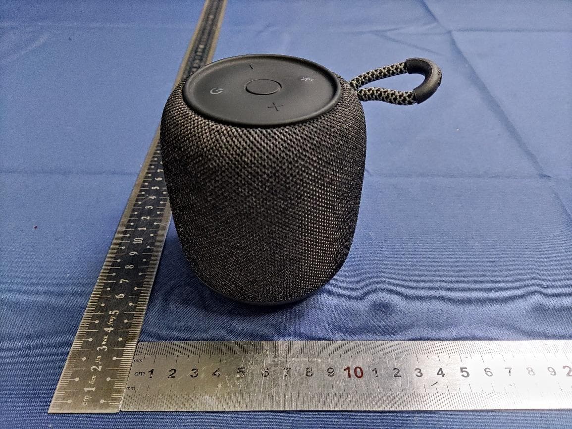
Feb 05, 2024Portable Bluetooth Speaker
Equipment Class
DSS - Part 15 Spread Spectrum Transmitter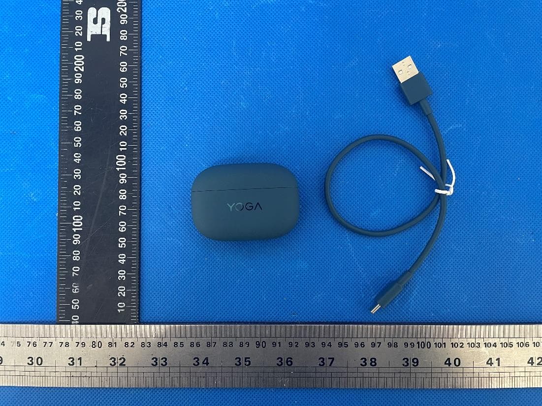
2AAP8-LT310
Jan 16, 2024Lenovo YOGA True Wireless Stereo Earbuds
Equipment Class
DTS - Digital Transmission System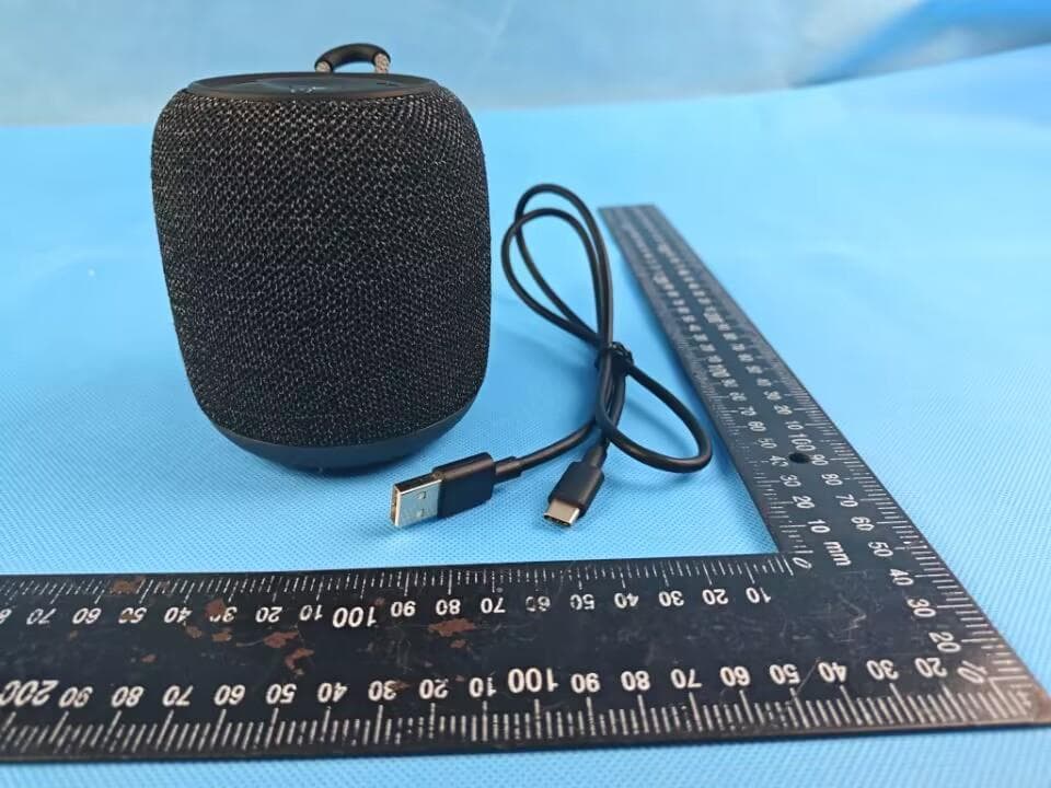
2AAP8-VIFA150
Sep 27, 2023Vifa AI Intelligent Speaker
Equipment Class
DTS - Digital Transmission System
2AAP8-VIFA062
Jul 06, 2023Portable Wireless Speaker
Equipment Class
DSS - Part 15 Spread Spectrum Transmitter
2AAP8-VIFANORDIC3-2
Jan 09, 2023Portable Wireless Speaker
Equipment Class
DSS - Part 15 Spread Spectrum Transmitter