2AAPHSX1TRANSMITTER
STETSOM ELECTRONICS USA INC.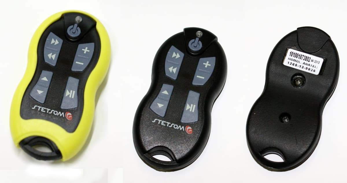
Click to zoom
Application Details
- Equipment Class
- DSC - Part 15 Security/Remote Control Transmitter
- Date of Grant
- Aug 22, 2013
- Application Purpose
- Original Equipment
- Date of Application
- Aug 12, 2013
- Equipment Note
- TRANSMITTER
- Frequency Range
- 433.92000000 - 433.92000000
- Company
- STETSOM ELECTRONICS USA INC.
- Country
- United States
Documents & Files
Document Text
Text extracted from the exhibit documents filed with the FCC. Open a document above to read the original.
Users Manual
01 02 03 01 02 03 Power Central: 6 a 16V dc Control: Battery CR2032 - 3,0V Max Consumption Central: 35mA Control: 10mA Technical Specifications Max. Range in open area: 200m Modulation: FSK Central frequency of transmission: 433,92 MHZ Max. transmit power: 10mW Dimensions Central: 57,5 x 33 x 12 mm Control: 82,7 x 42 x 15,7 mm Weight Central: 46g Control: 37g 15 14 16 01 02 03 04 05 06 09 11 10 12 13 Front Rear 08 07 Control TX1 Central RX1 Long Distance Remote Control Quick Guide SX1 Rev 01 - Apr/2013 17 Alcance Control Manual Presentation: The Alcance Control was developed to control audio and video equipment over long distances. Due to his radio frequency technology (RF), you can control your equipment up to 200m away in open area (visual). Its transmission is made in FSK, reducing external interference; its code is encrypted with "Rolling Code” technology that prevents copying and retransmission signal. Description: 01 - Indicator LED of Transmission / Low Battery. 02 - Power key 03 - Forward and Reward Key 04 - Volume (+) and Volume (-) Key 05 - Up / Down Key 06 - Play / Pause Key 07 - Neck Strap 08 - Cord Neck 09 - Protective Holster 10 - Antenna 11 - Indicator Led 12 - IR Transmitter Cable (3m) 13 - Polarized Power Cable (50cm) 14 - Infra Red Receiver 15 - Sync Key (Sync) 16 - Learning Key (LRN) 17 - Pin Programming Resources: - The central RX1 can receive commands from up to 7 controls TX1, allowing each team member has a control. - A TX1 control can control several devices, even different brands. - Easy Synchronism. Doesn’t need to use the Assistance Service when purchased new controls. - Has several handset models in memory plus function "Learning" that enables the programming of the vast majority of market controls. - Low battery indicator on the control and central. Installing your Alcance Control: The Central can be installed hidden or somewhere visible to monitoring your indicator Led (11). The most important is that your antenna (10) should be not blocked by the bodywork of the car that acts as a shield to radio frequency transmission. It can run close to the edge of one of the windows once the car glass does not block the reception, or stay inside the panel. The power cord (13) is polarized. The wire that has a white stripe should be connected to the positive pole of the battery and the black wire to negative. The Infra-Red transmitter (12) must to be fixed at some point inside the car pointing to CD/MP3-Player panel. Assure that nothing exists between the two. Synchronizing Your Alcance Control: The synchronizing is necessary in order the TX1 paring the central RX1. The Alcance Control goes out from the factory synchronized. This operation is required again in case the owner to acquire new controls TX1 for your team, replacement or loss of sync. The Alcance Control allows up to 7 TX1 controls are synchronized on the same RX1 central. Each control is addressed in the RX1 central by the TX1 control buttons. CAUTION: Before performing the synchronizing, make sure that there is any other control TX1 within the same area being operated. It may to cause interference. Follow the steps below to synchronize: 1. Press the Sync (15) key on the Central RX1. The indicator LED (11) flashes. 2. Press one of the keys on the TX1, except the Power key (2). 3. The indicator LED (11) stops flashing. The synchronizing is completed. To synchronize more than one control (maximum 7), repeat the steps 1-3 choosing different keys in step 2. If you press the same key that has already been used for the earlier synchronizing, this new control will override the earlier, canceling your synchronizing. You can also undo the synchronizing of each control or all at the same time. Undoing the synchronizing of a single control: 1. Press the Sync (15) key on the Central RX1. The Indicator LED(11) flashes. 2. Press the Power (2) key in the control TX1 that you want to exclude. 3. The Indicator LED(11) stops flashing. The exclusion is completed. Exemple: Programming for CD/MP3-Player - PIONEER CD/MP3-Player Keys DEH-8380SD 0203 04 05 01 02 Undoing the synchronizing of all controls: 1. Press the Sync (15) key on the Central RX1. The Indicator LED(11) flashes. 2. Press the Learn (16) key on the Central RX1. The Indicator LED(11) will flash faster and stop. - The exclusion is completed. Setting the Alcance Control for your CD/MP3-Player: For the correct operation of your Alcance Control, the central RX1 should be programed for the model of your CD/MP3-Player. This can be done in two ways, Direct Mode (using CD/MP3-Player models stored in the memory) or Learning Mode. Direct Mode: 1. Look for the code of your CD/MP3-Player in the "Memory” Code Table (See our Manual ). 2. Press the Learn (16) key on the Central RX1. The Indicator LED(11) flashes. 3. Press the Sync (15) key on the Central RX1. The Indicator LED(11) will flash faster. 4. Press on the TX1 control the first key of the table, the Indicator LED(11) stops for a moment and start blinking again. 5. Press the second key of the table. The Indicator LED(11) will stop. - Your central RX1 is programed to the chosen CD/MP3-Player. If your DVD/CD/MP3-Player is not listed in the memory code table, try the default setting of your brand DVD/CD/MP3-Player. (See the Memory Code Table). Passos 2 e 3 01 02 03 05 Once done the Learning Mode, the learned control is saved in me- mory (See the "Memory" Code Table) and can be accessed anytime in Direct Mode. For programming the central RX1 with a CD/MP3-Player that is not in memory, it should use the Learning Mode where each key of your interest on the original remote control of your CD/MP3-Player should be programed one by one. To do this, follow these steps: NOTE: Choose a dimly lit environment; prefer one area with no fluorescent lamp, or in the car, because external light may interfere in the Infra-Red Receiver (14) of Central Rx1. Learning Mode: 1. Press Learn (16) key on the Central RX1. The Indicator LED(11) flas…
Text truncated - open the document above for the full version.
External Photos
APPLICANT: STETSOM ELECTRONICS USA INC. FCC ID: 2AAPHSWX1 EXTERNAL PHOTOS
ID Label/Location Info
FCC ID LABEL SAMPLE FCC ID: 2AAPHSX1
Internal Photos
APPLICANT: STETSOM ELECTRONICS USA INC. FCC ID: 2AAPHSWX1 INTERNAL PHOTOS
Test Report
APPLICANT: STETSOM ELECTRONICS USA INC. FCC ID: 2AAPHTX1 REPORT: S\Stetsom\1267AUT13\1267AUT13TestReport.docx Page 2 of 14 mdea 09.20.2007 FCC PART 15.231 TEST REPORT LOW POWER UNLICENSED TRANSMITTER Applicant STETSOM ELECTRONICS USA INC. Address 201 S. Biscayne Blvd.., Ste. 1200 Miami Florida 33131 USA FCC ID 2AAPHTX1 Product Description TRANSMITTER Date Sample Received 7/24/2013 Date Tested 8/2/2013 Tested By Joe Scoglio Approved By Joe Scoglio Timco Report No. 1267AUT13TestReport.docx Test Results Pass Fail THE ATTACHED REPORT SHALL NOT BE REPRODUCED EXCEPT IN FULL WITHOUT THE WRITTEN APPROVAL OF TIMCO ENGINEERING, INC. 849 NW STATE ROAD 45 NEWBERRY, FL 32669 USA PH: 888.472.2424 OR 352.472.5500 FAX: 352.472.2030 EMAIL: [email protected] HTTP://WWW.TIMCOENGR.COM Certificate # 0955-01 APPLICANT: STETSOM ELECTRONICS USA INC. FCC ID: 2AAPHTX1 REPORT: S\Stetsom\1267AUT13\1267AUT13TestReport.docx Page 3 of 14 mdea 09.20.2007 TABLE OF CONTENTS GENERAL REMARKS ...................................................................................................... 4 REPORT SUMMARY ....................................................................................................... 5 TEST ENVIRONMENT ..................................................................................................... 5 TEST SETUP................................................................................................................... 5 DUT SPECIFICATION ..................................................................................................... 6 MANUFACTURE DECLARATION OF COMPLIANCE WITH PART 15.231(A) ..................... 7 TEST EQUIPMENT LIST ................................................................................................. 8 TEST PROCEDURES ...................................................................................................... 9 RADIATION INTERFERENCE ........................................................................................ 10 CALCULATION OF DUTY CYCLE .................................................................................. 12 OCCUPIED BANDWIDTH .............................................................................................. 13 POWER LINE CONDUCTED INTERFERENCE ............................................................... 14 APPLICANT: STETSOM ELECTRONICS USA INC. FCC ID: 2AAPHTX1 REPORT: S\Stetsom\1267AUT13\1267AUT13TestReport.docx Page 4 of 14 mdea 09.20.2007 GENERAL REMARKS The attached report shall not be reproduced except in full without the written permission of Timco Engineering Inc. Summary The device under test does: fulfill the general approval requirements as identified in this test report not fulfill the general approval requirements as identified in this test report Attestations This equipment has been tested in accordance with the standards identified in this test report. To the best of my knowledge and belief, these tests were performed using the measurement procedures described in this report. All instrumentation and accessories used to test products for compliance to the indicated standards are calibrated regularly in accordance with ISO 17025 requirements. Certificate # 0955-01 I attest that the necessary measurements were made, under my supervision, at: Timco Engineering Inc. 849 NW State Road 45 Newberry, Fl 32669 Authorized Signatory Name: Joe Scoglio Project Engineering Manager Date: 8/2/2013 APPLICANT: STETSOM ELECTRONICS USA INC. FCC ID: 2AAPHTX1 REPORT: S\Stetsom\1267AUT13\1267AUT13TestReport.docx Page 5 of 14 mdea 09.20.2007 REPORT SUMMARY Disclaimer The test results only relate to the item tested. Applicable Rule(s) FCC Pt 15.231, Pt 15.209, Pt 15.207, ANSI C63.4: 2003 TEST ENVIRONMENT Test Facility The test sites are located at 849 NW State Road 45 Newberry, FL 32669 USA. Test Condition: Temperature: 26ºC Relative humidity: 50% TEST SETUP Test Exercise (e.g software description, test signal, etc.): The DUT was placed in continuous transmit mode of operation. Deviation from the standard(s) No deviation from the standard(s) Modification to the DUT: No modification was made to the DUT. Supporting Peripheral Equipment Not applicable. The device is a stand-alone remote control radio. APPLICANT: STETSOM ELECTRONICS USA INC. FCC ID: 2AAPHTX1 REPORT: S\Stetsom\1267AUT13\1267AUT13TestReport.docx Page 6 of 14 mdea 09.20.2007 DUT SPECIFICATION Applicant STETSOM ELECTRONICS USA INC. Description TRANSMITTER FCC ID TX1 Model Number TX1 Frequency Range 433.92 DUT Power Source 110–120Vac/50– 60Hz DC Power Battery Operated Exclusively Test Item Prototype Pre-Production Production Type of Equipment Fixed Mobile Portable APPLICANT: STETSOM ELECTRONICS USA INC. FCC ID: 2AAPHTX1 REPORT: S\Stetsom\1267AUT13\1267AUT13TestReport.docx Page 7 of 14 mdea 09.20.2007 MANUFACTURE DECLARATION OF COMPLIANCE WITH PART 15.231(A) Item Description Yes No 1 Does this device transmit a signal that is only used to control another device? X 2 Does this device send data with this control signal? X 3 Does this device send data? Data is, things like: temperature, wind direction, fluid amount, rate of flow, etc. X 4 Does this device transmit continuously or automatically? X 5 If manually operated does this device stop transmitting within 5 seconds of releasing the button? X 6 If automatically operated does it deactivate 5 seconds after activation? 7 Does it transmit at regular predetermined intervals? X 8 Does it poll or send supervisory information? X If yes does it do a system integrity check? How often? 9 Is this a fire, security or safety of life device? X If YES does the device stop transmitting after the alarm condition is satisfied? 10 Duty cycle: Maximum on-time? 77.4 If YES, on-time in 100 ms? If Other, please specify here On time in 100 11 Modulation technique: Please specify the modulation of the test sample, FM, or AFSK, or FSK, or on-off keying, or others? FSK APPLICANT: STETSOM ELECTRONICS USA INC. FCC ID: 2AAPHTX1 REP…
Text truncated - open the document above for the full version.
Contact Information
Applicant
MARI ORRIGO(EXPORT MANAGER)
Test Firm
Timco Engineering, Inc.Bruno Clavier
Technical Specifications
| # | Rule Parts | Frequency Range | Power Output |
|---|---|---|---|
| 1 | 15.231 | 433.92 MHz - 433.92 MHz | - |