2AAQXA310500V5R1BMM Activator
BMT Holdings Pty Ltd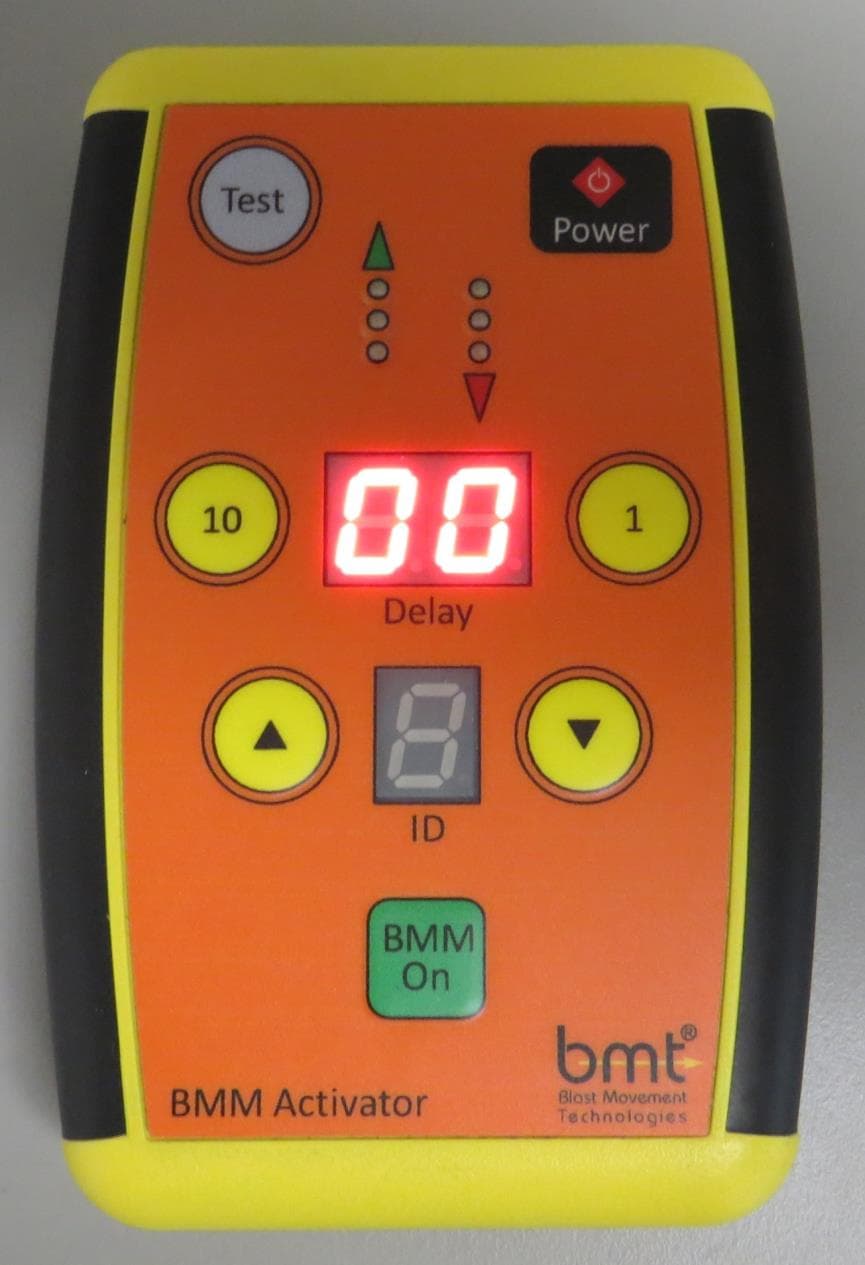
Click to zoom
Application Details
- Equipment Class
- DCD - Part 15 Low Power Transmitter Below 1705 kHz
- Date of Grant
- Sep 19, 2013
- Application Purpose
- Original Equipment
- Date of Application
- Sep 19, 2013
- Equipment Note
- BMM Activator
- Frequency Range
- 0.11110000 - 0.11110000
- Company
- BMT Holdings Pty Ltd
- Country
- Australia
Documents & Files
Document Text
Text extracted from the exhibit documents filed with the FCC. Open a document above to read the original.
Users Manual
BMM ® System Manual BMM Activator Type 5 Solutions to Reduce Ore Loss and Dilution BMM ® System Manual – BMM Activator i Activator Type 5-Manual_1211_A4_FCC November 2012 TABLE OF CONTENTS BMM ® System Manual _____________________________________________________________ 1 BMM Activator ___________________________________________________________________ 1 1 Introduction _________________________________________________________________ 1 2 Using the BMM activator ______________________________________________________ 1 2.1 Hardware .......................................................................................................................... 1 2.2 Quick Start ........................................................................................................................ 2 2.3 Test Button........................................................................................................................ 3 2.4 Delayed Start-up .............................................................................................................. 3 2.5 Miscellaneous ................................................................................................................... 3 3 Troubleshooting _____________________________________________________________ 4 4 Specifications ________________________________________________________________ 4 BMM ® System Manual – BMM Activator 1 www.bmt.com.au 1 INTRODUCTION Blast Movement Monitors (BMM ® s) are delivered to site with the transmitter in a low power hibernation state. The BMM ® transmitter must be switched on before installation into the blast. The BMM ® can only be switched on by a specially coded signal which eliminates accidental activation. The BMM Activator (Activator) is a remote control device that provides the signal to turn a BMM ® on and to also assign a delayed start-up time if required. It is also useful to quickly determine if a BMM ® is transmitting. The signal from the Activator is low power to limit its range to approximately 0.5 m. This is to control which BMM ® s are switched on. WARNING All BMM ® s that are within range of the Activator will switch on when the BMM On button is pressed. Ensure other BMM ® s are well out of range (several metres to be certain) of the BMM ® to be turned on or programmed. Do not play with the Activator anywhere near BMM ® s. Store BMM ® s in a separate location to the Activator 2 USING THE BMM ACTIVATOR 2.1 Hardware The Activator consists of a tough ABS plastic case with a sealed low-profile keypad. The battery compartment can be accessed by pressing and sliding a section at the back of the case. Use a good quality 9 V alkaline or rechargeable Nickel Metal Hydride (NiMH) battery. The BMM ® System kit is supplied with an Aquapak. It is a transparent case that is 100% waterproof when closed. It has a cord for hanging around the user’s neck, which frees up hands for other tasks and eliminates the chance of dropping the Activator into a blast hole. It is strongly advised that the Activator be placed inside the supplied Aquapak and hung around the user’s neck. BMM ® System Manual – BMM Activator 2 www.bmt.com.au 2.2 Quick Start Turn the Activator on by pressing the Power button ❶. The digital display ❹ will quickly show the battery voltage, and then show “00”. Once less than 8.5, it is close to flat so have a spare battery available. Press the yellow 1 or 10 button ❸ to select the desired start-up delay time in multiples of 4 hours up to a maximum of 36 hours. The display ❹ shows the actual delay in hours. Position the Activator close to the BMM ® to be switched on (within 100 mm), and press the green BMM On button ❷ briefly – the green (transmit) LEDs ❺ will illuminate briefly. Activation is more reliable if the Activator is pointing down at the BMM ® (approx. 45) as shown in the photo in Section 2.1. If the transmitter switches on, the red (receive) LEDs ❻ will illuminate and an audible tone will be generated at regular intervals (beep, beep, beep, beep...). Keep the Activator within range of the BMM ® for at least ten seconds, to make sure the BMM ® continues to transmit. As a final check to make sure the BMM ® is still transmitting, move the Activator out of range of the BMM ® and then back within range. If the BMM ® does not turn on, the respective transmit and receive aerials may be unfavourably orientated, so move the Activator around the BMM ® by 90° and try again. WARNING The BMM ® cannot be switched off once activated In the future, the BMMs will be able to be assigned an ID code that will make each one uniquely identifiable in a blast. The Type 5 Activator has been designed with this feature but it is not enabled at this time. BMM ® System Manual – BMM Activator 3 www.bmt.com.au 2.3 Test Button The Test function only confirms that the BMM ® is functioning by turning it on briefly. It is not necessary to use this during normal use and it is best to avoid using this function onsite. If Test Mode has to be used to confirm a BMM ® is functioning, position the activator as previously described and press the grey Test button ❼ (the display ❹ can be any number). The BMM ® will then transmit for about five seconds and then turn off, ready to be switched on normally. 2.4 Delayed Start-up The BMM ® transmits at constant power for about 10 – 12 hours so to accurately calculate the depth of the BMM ® s after the blast, they must be located within this period. The BMM ® will continue to transmit for about 24 hours beyond this time (total ~36 hrs) but the signal will slowly decrease and eventually switch off. If the BMM ® is located after the initial 10 hr period, its horizontal location will be accurate but not its depth. The delayed start-up feature was specifically designed for mines that could not access the muckpile immediately after blasting due to light and/or safety reasons. It can also be used to install the BMM ® s well before the blast for operational reasons…
Text truncated - open the document above for the full version.
External Photos
SAFE OPERATING PROCEDURE No: SOP-##### Document1 Page 1 of 5 BMM Activator External Photos Photograph Number Description 1 TOP VIEW 2 BOTTOM VIEW 3 RIGHT SIDE VIEW 4 LEFT SIDE VIEW 5 FRONT VIEW 6 REAR VIEW SAFE OPERATING PROCEDURE No: SOP-##### Document1 Page 2 of 5 Figure 1: Top View SAFE OPERATING PROCEDURE No: SOP-##### Document1 Page 3 of 5 Figure 2: Bottom View SAFE OPERATING PROCEDURE No: SOP-##### Document1 Page 4 of 5 Figure 3: Right Side View Figure 4: Left Side View SAFE OPERATING PROCEDURE No: SOP-##### Document1 Page 5 of 5 Figure 5: Front View Figure 6: Rear View
ID Label/Location Info
SAFE OPERATING PROCEDURE No: SOP-##### Document5 Page 1 of 2 LABEL ARTWORK SAFE OPERATING PROCEDURE No: SOP-##### Document5 Page 2 of 2 LABEL LOCATION The Activator is shipped with the Battery Removed. Therefore the recipient of the device will see the Label. Figure 1: Label Location (Closer View) Figure 2: Label Location
Internal Photos
EMC ENGINEERS & LABORATORIES EMC Bayswater Pty Ltd 52 Holloway Drive Bayswater, Victoria, 3153, Australia Telephone: +61 3 9762 4111 Facsimile: +61 3 9762 8519 Email: [email protected] ABN: 49 112 221 333 Photograph Annex B: Internal - EUT Photographs Blast Movement Technologies Ball shaped Transmitter (BMM), BMM Detector & BMM Activator Blast movement probe detection system REPORT: E1306-0348-1 Annex B DATE: June, 2013 This document may not be reproduced, except in full, without written approval from EMC Bayswater Pty Ltd. Annex B – Photographs Number Photograph Description 1 2 3 4 5 EUT – Internal view – BMM Activator 6 7 8 9 10 11 12 EUT – Internal view – BMM Detector system This document may not be reproduced, except in full, without written approval from EMC Bayswater Pty Ltd. Photograph 1 Photograph 2 Photograph 3 Photograph 4 Photograph 5 Photograph 6 This document may not be reproduced, except in full, without written approval from EMC Bayswater Pty Ltd. Photograph 7 Photograph 8 Photograph 9 Photograph 10 Photograph 11 Photograph 12
Test Report
EMC ENGINEERS & LABORATORIES EMC Bayswater Pty Ltd 52 Holloway Drive Bayswater, Victoria, 3153, Australia Telephone: +61 3 9762 4111 Facsimile: +61 3 9762 8519 Email: [email protected] ABN: 49 112 221 333 EMC COMPLIANCE REPORT In accordance with: CFR47 FCC Part 15, Subpart B, Section 15.109 CFR47 FCC Part 15, Subpart C, Section 15.209 Blast Movement Technologies Ball shaped Transmitter (BMM), BMM Detector & BMM Activator* *See Product sample, configurations and modifications section for further details Blast movement probe detection system REPORT: E1306:0348:1 Rev1 DATE: September, 2013 EMC Bayswater Test Report E1306:0348:1 Rev1 Page 2 of 29 Prepared by: Approved by: 18/09/2013 09:18 Clint Finch (Principal Engineer) Andrew Whiteford (General Manager) Date This document may not be reproduced, except in full, without written approval from EMC Bayswater Pty Ltd. Certificate of Compliance EMC Bayswater Test Report: E1306-0348-1 Rev1 Issue Date: September, 2013 Test Sample(s): Blast movement probe detection system Model No: Ball shaped Transmitter (BMM), BMM Detector & BMM Activator* Serial No: None stated *See Product sample, configurations and modifications section for further details Mr. Brane Pesic Blast Movement Technologies PO Box 73 Bellbowrie Queensland, 4070 Australia Phone No: +61 07 3202 9499 Client Details: e:mail: [email protected] Test Specification: CFR47 FCC Part 15, Subpart B, Section 15.109 CFR47 FCC Part 15, Subpart C, Section 15.209 Radiated Emissions Complied Results Summary: Conducted Emissions Complied* *Not applicable the EUT was battery powered only Test Date(s): 6 th and 7 th of June 2013 Test House (Issued By) EMC Bayswater Pty Ltd 52 Holloway Drive Bayswater Victoria, 3153 Australia FCC Registration number: 419968 Phone No: +61 3 9762 4111 e:mail: [email protected] Fax No: +61 3 9762 8519 Web: www.emcbayswater.com.au This is to certify that the necessary measurements were made by EMC Bayswater Pty Ltd, and that the modified Blast Movement Technologies, Ball shaped Transmitter (BMM), BMM Detector & BMM Activator* Blast movement probe detection system (Serial No: None stated), have been tested in accordance with requirements contained in the appropriate commission regulations. EMC Bayswater Test Report E1306:0348:1 Rev1 Page 3 of 29 This document may not be reproduced, except in full, without written approval from EMC Bayswater Pty Ltd. EMC Compliance Report for Blast Movement Technologies Contents 1. Introduction.................................................................................................................... 4 2. Summary of Results ...................................................................................................... 4 3. Product Sample, Configuration & Modifications ......................................................... 5 3.1. Product Sample Details............................................................................................. 5 3.2. EUT Configuration .................................................................................................... 7 3.3. Modifications............................................................................................................. 7 4. Test Facility & Equipment ............................................................................................. 7 4.1. Test Facility............................................................................................................... 7 4.2. Test Equipment......................................................................................................... 7 5. Referenced Standards................................................................................................... 7 6. Maximum Fundamental Field Strength ........................................................................ 8 6.1. Test Procedure ......................................................................................................... 8 6.2. Limits ........................................................................................................................ 8 6.3. Test Results.............................................................................................................. 8 7. Radiated Spurious and Harmonic Emissions............................................................ 11 7.1. Test Procedure ....................................................................................................... 11 7.2. Limits ...................................................................................................................... 11 7.3. Test Results............................................................................................................ 11 8. Radiated Emissions..................................................................................................... 13 8.1. Test Procedure ....................................................................................................... 13 8.2. Limits ...................................................................................................................... 13 8.3. Test Results............................................................................................................ 13 9. Conclusion................................................................................................................... 15 Appendix A – Test Equipment.......................................................................................... 16 Appendix B – Photographs............................................................................................... 17 Appendix C – Measurement Graphs................................................................................. 19 EMC Bayswater Test Report E1306:0348:1 Rev1 Page 4 of 29 This document may not be reproduced, except in full, without written approval from EMC Bayswater Pty Ltd. 1. Introduction Electromagnetic Compatibility (EMC) tests were performed on a Blast Movem…
Text truncated - open the document above for the full version.
Test Setup Photos
EMC ENGINEERS & LABORATORIES EMC Bayswater Pty Ltd 52 Holloway Drive Bayswater, Victoria, 3153, Australia Telephone: +61 3 9762 4111 Facsimile: +61 3 9762 8519 Email: [email protected] ABN: 49 112 221 333 Photograph Annex C: Test set-up Photographs Blast Movement Technologies Ball shaped Transmitter (BMM), BMM Detector & BMM Activator Blast movement probe detection system REPORT: E1306-0348-1 Annex C DATE: June, 2013 This document may not be reproduced, except in full, without written approval from EMC Bayswater Pty Ltd. Annex C – Photographs Number Photograph Description 1 BBM - Radiated measurements – Setup below 30MHz 2 BBM - Radiated measurements – EUT X Orientation 3 BBM - Radiated measurements – EUT Y & Z Orientation 4 BBM Activator - Radiated measurements – Setup below 30MHz 5 BBM Activator - Radiated measurements – EUT X Orientation 6 BBM Activator - Radiated measurements – EUT Y Orientation 7 BBM Activator - Radiated measurements – EUT Z Orientation 8 BBM - Radiated measurements – 30MHz to 1GHz 9 BBM Activator - Radiated measurements – 30MHz to 1GHz 10 BBM Detector - Radiated measurements – 30MHz to 1GHz This document may not be reproduced, except in full, without written approval from EMC Bayswater Pty Ltd. Photograph 1 Photograph 2 Photograph 3 Photograph 4 Photograph 5 Photograph 6 This document may not be reproduced, except in full, without written approval from EMC Bayswater Pty Ltd. Photograph 7 Photograph 8 Photograph 9 Photograph 10
Contact Information
Applicant
Jacques Janse(Managing Director)
Technical Contact
Non-Technical Contact
Blast Movement TechnologiesDarren Thornton
Test Firm
EMC Bayswater Pty LtdClint Finch
Technical Specifications
| # | Rule Parts | Frequency Range | Power Output |
|---|---|---|---|
| 1 | 15C | 0.1111 MHz - 0.1111 MHz | - |