2AAS7-BFXArm Automatic Blood Pressure Monitor
SHENZHEN PUMP MEDICAL SYSTEM CO., LTD.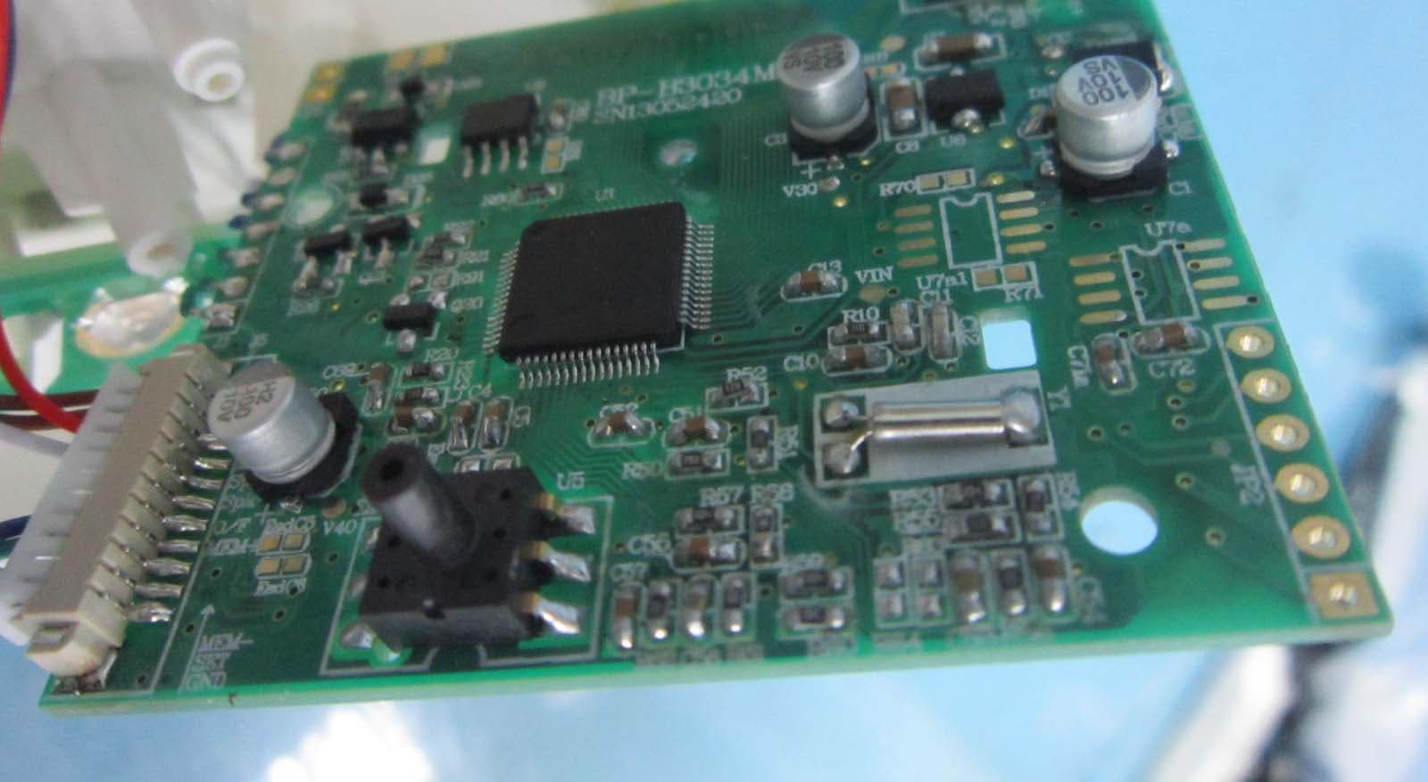
Click to zoom
Application Details
- Equipment Class
- DTS - Digital Transmission System
- Date of Grant
- Sep 01, 2013
- Application Purpose
- Original Equipment
- Date of Application
- Sep 01, 2013
- Equipment Note
- Arm Automatic Blood Pressure Monitor
- Frequency Range
- 2402.00000000 - 2480.00000000
- Country
- China
Documents & Files
Document Text
Text extracted from the exhibit documents filed with the FCC. Open a document above to read the original.
Users Manual
Rev. A1 1 Arm Automatic Blood Pressure Monitor Instruction Manual BF1215 (0B) Table of Contents 1. Safety Information ................................................................................................... 2 1.1 Warning .............................................................................................................................. 2 1.2 Precaution .......................................................................................................................... 2 2. Product Feature ....................................................................................................... 3 3. Pre Measurement ..................................................................................................... 5 3.1 Battery ................................................................................................................................ 5 3.2 Power Adapter(Optional) ............................................................................................ 5 3.3 Setting date and time ........................................................................................................ 6 4 Take a measurement ................................................................................................. 6 4.1 Important Noted ................................................................................................................ 6 4.2 Fitting the cuff ................................................................................................................... 7 4.3 Body posture during measurement .................................................................................. 7 4.4 Take Measurement ............................................................................................................ 8 4.5 Data Transmission ............................................................................................................. 9 4.6 Memory .............................................................................................................................. 9 5. Error Indication ....................................................................................................... 9 6. Trouble Shooting .................................................................................................... 10 7. Specification ........................................................................................................... 10 8.About Blood Pressure .......................................................................................... 15 8.1 What is Blood Pressure? ................................................................................................. 15 8.2 What is high blood pressure? ......................................................................................... 15 8.3 What is morning hypertension (morning surge)? ........................................................ 15 Reference Standard .................................................................................................... 16 Blood Pressure Measurement Chart ........................................................................ 16 Guarantee Card ......................................................................................................... 17 Rev. A1 2 1. Safety Information 1.1 Warning • Self diagnosis and treatment which use measured results may be dangerous. Follow the instructions of your physician or licensed healthcare provider. • Those who have arrhythmia, diabetes, blood circulation or apoplexy problem, please use under the physician’s instruction. • If cuff inflation doesn’t stop, remove the cuff or power off the unit, otherwise, it may result in a hazard condition. • This equipment is not suitable for the neonate, infant and who can't communicate or interact independently. • Do not use the blood pressure monitor for any other purpose except measuring the blood pressure of human body. • Only take measurement with the manufacturer supplied cuff or AC adapter, or else it will lead to inaccurate results. • Do not use the blood pressure monitor when you are close proximity to strong static electricity or electromagnetic fields, and avoid using the mobile during measurement. • Do not use in combination with a hyperbaric oxygen therapy device, or in an environment where combustible gas may be generated. • Do not install the unit in the following locations: - Locations subject to vibration such as ambulances and emergency helicopters. - A location where there is gas or flame. - A location where there is water or steam. - A location where chemicals are stored. - A location where the unit may easily fall. • The common arrhythmia such as atrial premature beats, premature ventricular and atrial fibrillation will lead to inaccurate results or error. • Measurements or stores need to take into account environment variables, or else it would lead to the inaccurate measurement. • When using or replacing the AC adapter and batteries, the operator not to touch those parts and the patient simultaneously. • The battery has positive/negative polarity. If the battery does not connect well to the unit, do not forcibly connect it. • Do not use Luer lock. If Luer lock connectors are used in the construction of tubing, there is a possibility that they might be inadvertently connected to intravascular fluid systems, allowing air to be pumped into a blood vessel. 1.2 Precaution • Do not attempt to disassemble, repair or modify the blood pressure monitor or hand cuff. • Avoid high temperature, moisture, dust and direct sunlight. • Clean the body with soft dry cloth dipped in a concentration of 75% medical alcohol. • Do not wet or cleaning the cuff with water. • Clean the cuff with soft dry cloth after measurement. Rev. A1 3 • Do not use at extremely high temperature, high humidity, or high altitude. Use only within the required ambient conditions. • Do not place heavy objects on the AC adapter cable, or allow the unit to sit…
Text truncated - open the document above for the full version.
Cover Letter(s)
Family models letter Hereby we: SHENZHEN PUMP MEDICAL SYSTEM CO., LTD. Declare All the models are same product just different model names. Models: BF1113(0B), BF1115(0B), BF1210(0B), BF1214(0B), BF1211(0B), BF1215(0B), BF1212(0B), BF1216(0B), BF1213(0B), BF1217(0B), BF3210(0B), BF3211(0B), BF3212(0B), BF3213(0B), BF1100, BF1110, BF1100(3), BF1110(3), BF1102, BF1112, BF1102(3), BF1112(3), BF1103, BF1113, BF1115, BF1105, BF1200, BF1210, BF1204, BF1214, BF1201, BF1211, BF1205, BF1215, BF1202, BF1212, BF1206, BF1216, BF1203, BF1213, BF1207, BF1217, BF3200, BF3201, BF3210, BF3211, BF3202, BF3203, BF3212, BF3213 Client’s signature: Client’s name / title: Wang Xiaofeng / General manager Contact information / address: 2F West, M7 Sinosteel Building, Maqueling Estate, High Technology Industrial Park, Nanshan District, Shenzhen 518057, China
Cover Letter(s)
SCS-F18: Project and Product Certification Representative Authorization Letter Page 1 of 2 Rev 3.0 775 Montague Expressway Milpitas, CA 95035 Tel: 408-526-1188 Fax: 408-526-1088 Email: [email protected] Project and Product Certification Representative Authorization Letter Reason for Amendment (current / obsolete) Revision History Approved Date From To Initial Release (obsolete) 1.0 1.0 Nov-14-2006 Revised wording (obsolete) 1.0 2.0 Sept–25-2007 Updated company template (current) 2.0 3.0 Jan-31-2012 SCS-F18: Project and Product Certification Representative Authorization Letter Page 2 of 2 Rev 3.0 SHENZHEN PUMP MEDICAL SYSTEM CO., LTD. 2013-8-19 To: SIEMIC, INC. 775 Montague Expressway, Milpitas, CA 95035 USA Dear Sir/Madam, Re: Project and Product Certification Representative Authorization Letter We, SHENZHEN PUMP MEDICAL SYSTEM CO., LTD. hereby authorize SIEMIC, INC. to act as a Certification Body for certifying for the following project(s): (Product description: Arm Automatic Blood Pressure Monitor, model name: BF1113(0B), BF1115(0B), BF1210(0B), BF1214(0B), BF1211(0B), BF1215(0B), BF1212(0B), BF1216(0B), BF1213(0B), BF1217(0B), BF3210(0B), BF3211(0B), BF3212(0B), BF3213(0B), BF1100, BF1110, BF1100(3), BF1110(3), BF1102, BF1112, BF1102(3), BF1112(3), BF1103, BF1113, BF1115, BF1105, BF1200, BF1210, BF1204, BF1214, BF1201, BF1211, BF1205, BF1215, BF1202, BF1212, BF1206, BF1216, BF1203, BF1213, BF1207, BF1217, BF3200, BF3201, BF3210, BF3211, BF3202, BF3203, BF3212, BF3213, FCC ID: 2AAS7-BFX) We affirm that between SIEMIC and SHENZHEN PUMP MEDICAL SYSTEM CO., LTD., any difference in understanding, including test plan, measurement methods, applicable standards and relevant procedures and processes have been resolved prior to commencement of testing activities. Sincerely, Client’s signature: Client’s name / title: Wang Xiaofeng / General manager Contact information / address: 2F West, M7 Sinosteel Building, Maqueling Estate, High Technology Industrial Park, Nanshan District, Shenzhen 518057, China
Cover Letter(s)
SCS-F19: Confidentiality Request Letter Page 1 of 2 Rev 3.0 775 Montague Expressway Milpitas, CA 95035 Tel: 408-526-1188 Fax: 408-526-1088 Email: [email protected] Confidentiality Request Letter Reason for Amendment (current / obsolete) Revision History Approved Date From To Initial Release (obsolete) 1.0 1.0 Nov-14-2006 Adding CFR 2.459 (obsolete) 1.0 2.0 August – 11 - 2008 Updated company template & Added text box (current) 2.0 3.0 Jan-31-2012 SCS-F19: Confidentiality Request Letter Page 2 of 2 Rev 3.0 SHENZHEN PUMP MEDICAL SYSTEM CO., LTD. 2013-8-19 To: Federal Communications Commission Authorization and Evaluation Division 7435 Oakland Mills Road Columbia, MD Subject: Permanent Confidentiality Request for FCC ID: 2AAS7-BFX We hereby request confidential treatment of information accompanying this application as outlined below: -Schematics - Detailed Block diagrams - Detailed Operational/Functional Description The above materials contain trade secrets and proprietary information not customarily released to the public. The public disclosure of these materials may be harmful to the applicant and provide unjustified benefits to its competitors. The applicant understands that pursuant to Section 0.457 & 0.459 of the Rules, disclosure of this application and all accompanying documentation will not be made before the date of the Grant for this application. Sincerely, Client’s signature: Client’s name / title: Wang Xiaofeng / General manager Contact information / address: 2F West, M7 Sinosteel Building, Maqueling Estate, High Technology Industrial Park, Nanshan District, Shenzhen 518057, China
RF Exposure Info
SAR Evaluation Report RF Exposure Compliance Requirement 1. Standard Requirement 15.247(b)(4) requirement: The conducted output power limit specified in paragraph (b) of this section is based on the use of antennas with directional gains that do not exceed 6dBi. Except as shown in paragraph (c) of this section. if transmitting antennas of directional gain greater than 6dBi are used. the conducted output power from the intentional radiator shall be reduced below the stated values in paragraphs (b)(1). (b)(2). and (b)(3) of this section. as appropriate. by the amount in dB that the directional gain of the antenna exceeds 6dBi. 2. Limits According to KDB447498 General RF Exposure Guidance v05 The 1-g and 10-g SAR test exclusion thresholds for 100 MHz to 6 GHz at test separation distances ≤ 50 mm are determined by: [(max. power of channel, including tune-up tolerance, mW)/(min. test separation distance, mm)] · [√f(GHz)] ≤ 3.0 for 1-g SAR and ≤ 7.5 for 10-g extremity SAR, where z f(GHz) is the RF channel transmit frequency in GHz z Power and distance are rounded to the nearest mW and mm before calculation z The result is rounded to one decimal place for comparison The test exclusions are applicable only when the minimum test separation distance is ≤ 50 mm and for transmission frequencies between 100 MHz and 6 GHz. When the minimum test separation distance is < 5 mm, a distance of 5 mm is applied to determine SAR test exclusion. 3. EUT RF Exposure The Max Conducted Peak Output Power is -3.25dBm(0.47315mW) in lowest channel, and the Max Conducted Average Output Power is less than 0.47315mW. The best case gain of the antenna is 0dBi. 0.47315/5*√2.402=0.15 ≤3.0 Conclusion: No SAR is required.
Test Report
Report No.: EESZF07110007-1 Page 1 of 34 FCC TEST REPORT Product Name : Arm Automatic Blood Pressure Monitor Trade Name : Model/Type reference : BF1113(0B), BF1115(0B), BF1210(0B), BF1214(0B), BF1211(0B), BF1215(0B), BF1212(0B), BF1216(0B), BF1213(0B), BF1217(0B), BF3210(0B), BF3211(0B), BF3212(0B), BF3213(0B), BF1100, BF1110, BF1100(3), BF1110(3), BF1102, BF1112, BF1102(3), BF1112(3), BF1103, BF1113, BF1115, BF1105, BF1200, BF1210, BF1204, BF1214, BF1201, BF1211, BF1205, BF1215, BF1202, BF1212, BF1206, BF1216, BF1203, BF1213, BF1207, BF1217, BF3200, BF3201, BF3210, BF3211, BF3202, BF3203, BF3212, BF3213 Serial Number : N/A Ratings : Input: AC 100-240V, 50-60Hz, 400mA Output: DC 6V, 0.5A FCC ID : 2AAS7-BFX Report Number : EESZF07110007-1 Date : Aug. 19, 2013 Regulations : See below Test Standards Results 47 CFR FCC Part 15 Subpart C 15.247:2012 PASS Prepared by: SHENZHEN PUMP MEDICAL SYSTEM CO.,LTD. 2/F West, M-7 Sinosteel Building, Maqueling Estate, Hi-Tech Industrial Park, Nanshan District, Shenzhen 518057, P.R.China Prepared by: Centre Testing International (Shenzhen) Corporation Hongwei Industrial Zone, 70 Area, Bao’an District, Shenzhen, Guangdong, China TEL: +86-755-3368 3666 FAX: +86-755-3368 3385 Tested by: Reviewed by: Approved by: Date: Aug. 19, 2013 Jimmy Li Lab manager Check No.: 1702050875 Report No.: EESZF07110007-1 Page 2 of 34 TABLE OF CONTENTS 1. GENERAL INFORMATION .......................................................................................... 4 2. PRODUCT INFORMATION .......................................................................................... 5 3. TEST SUMMARY ......................................................................................................... 6 4. MEASUREMENT UNCERTAINTY ............................................................................... 6 5. FACILITIES AND ACCREDITATIONS ......................................................................... 6 5.1 TEST FACILITY ................................................................................................................................ 6 5.2 TEST EQUIPMENT LIST.................................................................................................................. 6 5.3 LABORATORY ACCREDITATIONS AND LISTINGS ...................................................................... 7 6. SUPPORT EQUIPMENT .............................................................................................. 7 7. CONDUCTED EMISSION MEASUREMENT ............................................................... 8 7.1. LIMITS .............................................................................................................................................. 8 7.2. BLOCK DIAGRAM OF TEST SETUP .............................................................................................. 8 7.3. PROCEDURE OF CONDUCTED EMISSION TEST ....................................................................... 8 7.4. WORST CASE TEST GRAPHS AND TEST DATA ......................................................................... 9 8. 6DB BANDWIDTH MEASUREMENT ........................................................................ 11 8.1. LIMITS ............................................................................................................................................ 11 8.2. BLOCK DIAGRAM OF TEST SETUP ............................................................................................ 11 8.3. TEST PROCEDURE ...................................................................................................................... 11 8.4. TEST RESULT ............................................................................................................................... 11 9. POWER SPECTRAL DENSITY MEASUREMENT .................................................... 13 9.1. LIMITS ............................................................................................................................................ 13 9.2. BLOCK DIAGRAM OF TEST SETUP ............................................................................................ 13 9.3. TEST PROCEDURE ...................................................................................................................... 13 9.4. TEST RESULT ............................................................................................................................... 13 10. MAXIMUM PEAK CONDUCTED OUTPUT POWER MEASUREMENT .................... 15 10.1. LIMITS ............................................................................................................................................ 15 10.2. BLOCK DIAGRAM OF TEST SETUP ............................................................................................ 15 10.3. TEST PROCEDURE ...................................................................................................................... 15 10.4. TEST RESULT ............................................................................................................................... 15 11. BANDEDGE EMISSION MEASUREMENT ................................................................ 16 11.1. LIMITS ............................................................................................................................................ 16 11.2. BLOCK DIAGRAM OF TEST SETUP ............................................................................................ 16 11.3. TEST PROCEDURE ...................................................................................................................... 16 11.4. TEST RESULT ............................................................................................................................... 17 12. SPURIOUS RF CONDUCTED EMISSIONS MEASUREMENT ................................. 18 12.1. LIMITS ....................................................................................................................…
Text truncated - open the document above for the full version.
Contact Information
Applicant
Xiaofeng Wang(General manager)
Test Firm
Centre Testing InternationalLouisa Lu
[email protected]86-755-33683919
Technical Specifications
| # | Rule Parts | Frequency Range | Power Output |
|---|---|---|---|
| 1 | 15C | 2.40 GHz - 2.48 GHz | 473.20 µW |
Other Applications from SHENZHEN PUMP MEDICAL SYSTEM CO., LTD.
2AAS7-BFW
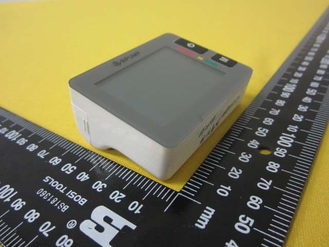
Jan 24, 2016Blood Pressure Monitor
Equipment Class
DTS - Digital Transmission System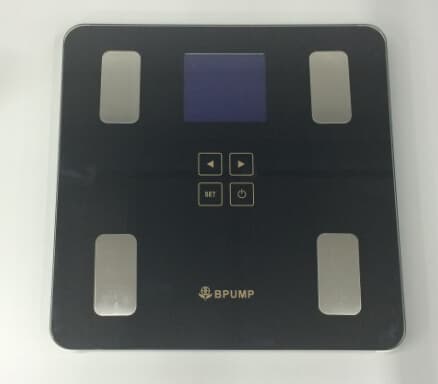
2AAS7-SFA
Nov 30, 2015Body Composition Analyzer and Scale
Equipment Class
DTS - Digital Transmission System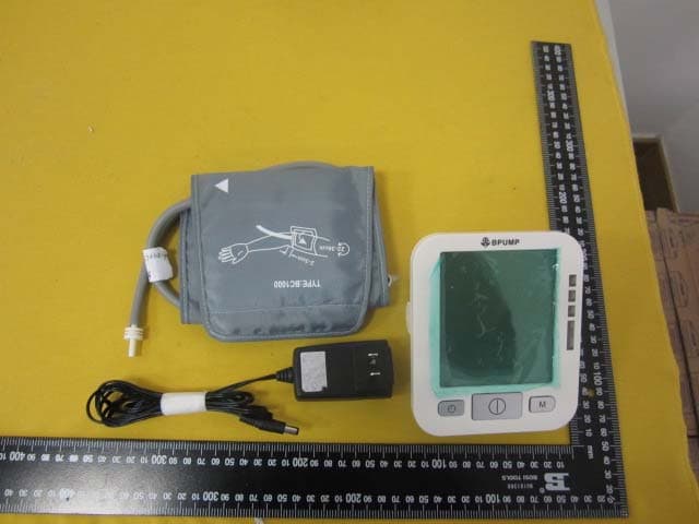
2AAS7-BFZ
Sep 17, 2015Arm Automatic Blood Pressure Monitor
Equipment Class
DTS - Digital Transmission System
2AAS7-BW6004B
Oct 19, 2014Arm Automatic Blood Pressure Monitor
Equipment Class
DTS - Digital Transmission System
2AAS7-BFY
Sep 04, 2013Blood Pressure Monitor
Equipment Class
DTS - Digital Transmission System