2AAT6001Muscle Oxygen Monitor
Fortiori Design LLC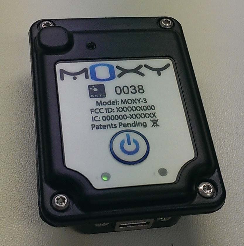
Click to zoom
Application Details
- Equipment Class
- DXT - Part 15 Low Power Transceiver, Rx Verified
- Date of Grant
- Sep 18, 2013
- Application Purpose
- Original Equipment
- Date of Application
- Sep 18, 2013
- Equipment Note
- Muscle Oxygen Monitor
- Frequency Range
- 2403.00000000 - 2480.00000000
- Company
- Fortiori Design LLC
- Country
- United States
Documents & Files
Document Text
Text extracted from the exhibit documents filed with the FCC. Open a document above to read the original.
Users Manual
©2013 Fortiori Design LLC All rights reserved. Under copyright laws, this manual may not be copied, in whole or in part, without the written consent of Fortiori. Moxy and are registered trademarks of Fortiori Design LLC US and International Patents Pending 09202013 Owner’s Manual Introduction Thank you for purchasing the Moxy Muscle Oxygen Monitor. Warning: Always consult your physician before starting or altering any exercise program. Technical Support: Contact technical support for your Moxy by emailing [email protected] or by calling 320-296-1010. Moxy Software: Go to www.moxymonitor.com/downloads to download a PC application that allows you to setup your Moxy and download data from it. Warning: There are no user serviceable parts inside the Moxy Sensor. Do not attempt to open the case. 2 Declaration of Conformity Refer to the Moxy website at www.moxymonitor.com 15 Industry Canada Compliance Category I radio communication devices comply with Industry Canada Standard RSS-210. Category II radio communication devices comply with Industry Canada Standard RSS-310. This device complies with Industry Canada license-exempt RSS standard(s). Operation is subject to the following two conditions: (1) this device may not cause interference, and (2) this device must accept any interference, including interference that may cause undesired operation of the device. Conformite aux normes d’Industrie Canada Les appareils de radiocommunication de catégorie I sont conformes á la norme RSS-210 d’Industrie Canada. Les appareils de radiocommunication de catégorie II sont conformes á la norme RSS-310 d’Industrie Canada. Cet appareil est conforme aux normes RSS sans licence d’Industrie Canada. Son fonctionnement est soumis au conditions suivantes: (1) cet appareil ne doit pas causer d’interférences et (2) doit accepter toute interférence, y compris les interférences pouvant entraîner un fonctionnement indésirable de l’appareil. 14 Muscle Oxygen Monitoring Moxy uses Near Infrared Spectroscopy to measure oxygen levels in muscle. Hemoglobin is the molecule in Red Blood Cells that carries oxygen and it changes color depending on whether it is carrying oxygen or not. Near Infrared light from the sensor travels from the emitter, through the skin, interacts with the muscle and is scatter back up to the detectors. The Moxy algorithm uses the information from the light striking the detectors to determine the Muscle Oxygen Saturation. The terms Muscle Oxygen Saturation, Muscle Oxygenation, or Muscle Oxygen are often used interchangeably. The abbreviation, SmO 2 is often used as well. SmO 2 is the percentage of hemoglobin in the capillaries of the muscle that is carrying Oxygen. The number can be from 0 to 100%. Muscle Oxygenation is a localized measurement. Even muscles that are close by each other like the Rectus Femoris and the Vastus Lateralis in the Quadriceps group can have different values. Contralateral muscles may also have different readings. Muscle Oxygen Monitoring can be used to determine optimal training zones, to monitor intensity, and to set an optimal race pace. Refer to the Moxy website at www.moxymonitor.com for more information. 3 Moxy Overview FCC Compliance Statement This device complies with part 15 of the FCC Rules. Operation is subject to the following two conditions: 1. This device may not cause harmful interference, and 2. This device must accept any interference received, including interference that may cause undesired operation. FCC WARNING This equipment has been tested and found to comply with the limits for a Class B digital device, pursuant to Part 15 of the FCC Rules. These limits are designed to provide reasonable protection against harmful interference in a residential installation. This equipment generates, uses and can radiate radio frequency energy and, if not installed and used in accordance with the instructions, may cause harmful interference to radio communications. However, there is no guarantee that interference will not occur in a particular installation. If this equipment does cause harmful interference to radio or television reception, which can be determined by turning the equipment off and on, the user is encouraged to try to correct the interference by one or more of the following measures: • Reorient or relocate the receiving antenna. • Increase the separation between the equipment and the receiver. • Connect the equipment into an outlet different from that to which the receiver is connected. • Consult the dealer or an experienced radio/TV technician for help. 4 13 Wearing the Sensor The Moxy sensor should be worn over the muscle of interest. Typically, the primary power producing muscles for the given exercise will be used but other muscles may also be of interest. The sensor should be secured so that the emitter and detector optodes are in contact with the skin. The optodes don’t need to be pressed to the skin, but just in contact. Even if the sensor loses contact during vigorous exercise by less than 1 mm, it will still function properly. The sensor can be secured with the Elastic strap or with athletic tape or it may be tucked under compression clothing. Care should be taken to not apply the strap or tape so tight as to restrict blood flow in the muscle. When using the Moxy sensor under bright lights or in direct sunlight, the light shield that is provided with the Moxy elastic strap will need to be used. The light shield has materials that block the ambient near infrared light. The shield blocks the light from travelling through the tissue and interfering with the Moxy detectors. The Moxy algorithm detects when there is too much ambient light and stops calculating Muscle Oxygen values. Moxy Overview 1. On/Off Button. Hold for 3 seconds to turn the sensor on or off. Holding the button for 10 seconds will cause a hard reset of the sensor microcontroller. A hard reset will not delete any stored data, but it will reset the clock that is used for timestamps in the st…
Text truncated - open the document above for the full version.
Block Diagram
Moxy Block Diagram.docx Page 1 of 1 Moxy Block Diagram Date: August 13, 2013 FCC ID: 2AAT6001 IC: 11333A‐001
External Photos
Moxy External Photos.docx Page 1 of 1 Moxy External Photos: Date: August 14, 2103 FCC ID: 2AAT6001 IC: 11333A‐001 Moxy External Photos.docx Page 1 of 1
ID Label/Location Info
FCC Label and Product Location Date: August 13, 2013 FCC ID: 2AAT6001 IC: 11333A‐001
Internal Photos
Moxy Internal Photos.docx Page 1 of 1 Moxy Internal Photos Date: August 14, 2013 FCC ID: 2AAT6001 IC: 11333A‐001
Operational Description
Moxy Brief Operational Description.docx Page 1 of 1 Moxy Brief Operational Description Date: August 13, 2103 FCC ID: 2AAT6001 IC: 11333A‐001 Moxy uses near infrared spectroscopy to measure muscle oxygen levels in the muscles of athletes while they exercise. The light emitter is 4 LEDs operating at wavelengths near 680, 720, 760, and 800 nm. There are two photodiode detectors at different distances from the emitter that detect light after it has been scattered through tissue. Moxy calculates the Muscle Oxygen Saturation and the Total Hemoglobin Concentration every 2 seconds. This data is stored on the sensor and it is transmitted out using the ANT+ wireless protocol. The data can be received by various ANT+ devices such as wristwatches, bike computers, personal computers, or smart phones. Moxy has a USB port for charging its battery and for downloading stored data after a workout. Moxy is controlled by a Nordic nRF51422 system‐on‐a‐chip microcontroller. This controller has an ARM controller and an ANT+ radio built in. The nRF51422 is driven by two different crystal oscillators. A 16 MHz crystal oscillator is used during normal operation. A 32.768 kHz oscillator is used to keep the real time clock operational on the microcontroller when all of its other functions are put to sleep in a power off mode. The microcontroller communicates over an SPI interface with a Burr Brown DDC114 Analog to digital converter that reads the signals in from the photodiodes. The microcontroller also supplies a 4 MHz clock signal for the A/D converter. The microcontroller is connected to a chip antenna to broadcast data.
Test Report
TEST REPORT Report Number: 101288157MIN-001 Project Number: G101288157 Testing performed on the MOXY-3 FCC ID: 2AAT6001 Industry Canada ID: 11333A-001 to 47 CFR Part 15. 249:2010 RSS- 210, Issue 8, 2010 RSS-Gen, Issue 3, 2010 47 CFR, Part 15:2010, §15.107 and §15.109, Class B / ICES-003, Issue 5:2012 For Fortiori Design LLC. Test Performed by: Test Authorized by: Intertek Testing Services NA, Inc. 7250 Hudson Blvd., Suite 100 Oakdale, MN 55128 USA Fortiori Design LLC 1155 West Shore Drive SW Hutchinson, MN 55350 USA Prepared by: Date: September 16, 2013 Simon Khazon Reviewed by: Date: September 16, 2013 Richard Blonigen This report is for the exclusive use of Intertek's Client and is provided pursuant to the agreement between Intertek and its Client. Intertek's responsibility and liability are limited to the terms and conditions of the agreement. Intertek assumes no liability to any party, other than to the Client in accordance with the agreement, for any loss, expense or damage occasioned by the use of this report. Only the Client is authorized to permit copying or distribution of this report and then only in its entirety. Any use of the Intertek name or one of its marks for the sale or advertisement of the tested material, product or service must first be approved in writing by Intertek. The observations and test results in this report are relevant only to the sample tested. This report by itself does not imply that the material, product, or service is or has ever been under an Intertek certification program. EMC Report No: 101288157MIN-001 FCC ID: 2AAT6001 IC ID: 11333A-001 Page 2 of 42 TABLE OF CONTENTS 1.0 GENERAL DESCRIPTION.......................................................................................................... 3 1.1 Product Description; Test Facility ....................................................................................... 4 1.3 Environmental conditions.................................................................................................... 5 1.4 Measurement uncertainty ................................................................................................... 6 1.5 Field Strength Calculation................................................................................................... 6 2.0 TEST SUMMARY.......................................................................................................................... 7 3.0 TEST CONDITIONS AND RESULTS........................................................................................ 8 3.1 Field strength of fundamental ............................................................................................. 8 3.2 Field strength of harmonics and spurious emissions ....................................................... 10 3.3 Bandwidth of Emissions.................................................................................................... 29 3.4 Transmitter power line conducted emissions ................................................................... 36 3.5 Receiver/digital device radiated emissions....................................................................... 37 3.6 Digital device conducted emissions.................................................................................. 41 4.0 TEST EQUIPMENT..................................................................................................................... 42 EMC Report No: 101288157MIN-001 FCC ID: 2AAT6001 IC ID: 11333A-001 Page 3 of 42 1.0 GENERAL DESCRIPTION Model: MOXY-3 Type of EUT: Muscle Oxygen Monitor Serial Number Proto FCC ID: 2AAT6001 Industry Canada ID: 11333A-001 Related Submittal(s) Grants: None Company: Fortiori Design LLC. Customer: Mr. Roger Schmitz Address: 1155 West Shore Drive SW Hutchinson, MN 55350 USA Phone: 320-296-1010 E-mail: [email protected] Test Standards: 47 CFR, Part 15:2010, §15.249 RSS–210, Issue 8, 2010 RSS-Gen, Issue 3, 2010 47 CFR, Part 15:2010, §15.107 and §15.109, Class B ICES-003, Issue 5:2012 Other Type of radio: Stand -alone Module Hybrid Date Sample Submitted: August 27 , 2013 Test Work Started: September 11, 2013 Test Work Completed: September 16, 2013 EMC Report No: 101288157MIN-001 FCC ID: 2AAT6001 IC ID: 11333A-001 Page 4 of 42 1.1 Product Description; Test Facility Product Description: Muscle Oxygen Monitor Operating Frequency 2403-2480 MHz Number of channels: 1 (factory pre selected in the frequency range 2403-2480MHz) Modulation: GFSK Emission Designator: 1M1F1D Antenna(s) Info: Integral 2.4 GHz Surface Mount Device (SMD) On-ground Antenna Antenna Installation: User Professional Factory Transmitter Power Configuration: Internal battery External power source 120VAC 230VAC 400VAC 3.8VDC from internal battery Other: Amp. 50Hz 60Hz Special Test Arrangement: N/A Test Facility Accreditation: A2LA (Certificate No. 1427.01) Test Methodology: Measurements performed according to the procedures in ANSI C63.10- 2009 EMC Report No: 101288157MIN-001 FCC ID: 2AAT6001 IC ID: 11333A-001 Page 5 of 42 1.2 EUT Configuration The equipment under test was operated during the measurement under the following conditions: - Standby - Continuous modulated mode - Continuous un-modulated - Continuous receiving mode - Normal (see below) Operating modes of the EUT: No. Description 1 The device was pre-programmed to operate continuously in low, middle, and upper frequency channels, one channel being transmitted at a given time. 2 Normal operation mode was used as a Receiving mode for FCC Part 15.109 Standard Cables: No. Type Length Designation Note None Support equipment/Services: No. Item Description None 1.3 Environmental conditions During the measurement the environmental conditions were within the listed ranges: Normal Temperature: 15-35 ° C Humidity: 30-60 % Atmospheric pressure: 86-106 kPa EMC Report No: 101288157MIN-001 FCC ID: 2AAT6001 IC ID: 11333A-001 Page 6 of 42 1.4 Measurement uncertainty The expanded uncertainty (k = 2) for radiated emissions from …
Text truncated - open the document above for the full version.
Contact Information
Applicant
Roger Schmitz(Chief Engineer)
Technical Contact
Fortiori Design LLCRoger William Schmitz
[email protected]320-296-1010
1155 West Shore Dr SW · Hutchinson, Minnesota · United States
Non-Technical Contact
Fortiori Design LLCRoger William Schmitz
[email protected]320-296-1010
Test Firm
Intertek Testing Services NA, Inc.Andrew Waytulonis
Technical Specifications
| # | Rule Parts | Frequency Range | Power Output |
|---|---|---|---|
| 1 | 15C | 2.40 GHz - 2.48 GHz | - |