2AATQ-H1LONGBOWWireless Sub Bass System
REL Acoustics Ltd.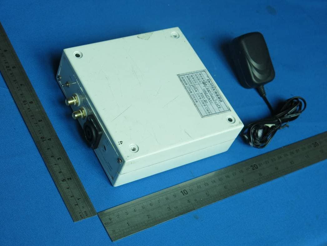
Click to zoom
Application Details
- Equipment Class
- DTS - Digital Transmission System
- Date of Grant
- Sep 16, 2013
- Application Purpose
- Original Equipment
- Date of Application
- Sep 16, 2013
- Equipment Note
- Wireless Sub Bass System
- Frequency Range
- 2406.00000000 - 2478.00000000
- Company
- REL Acoustics Ltd.
- Country
- United Kingdom
Documents & Files
Document Text
Text extracted from the exhibit documents filed with the FCC. Open a document above to read the original.
Users Manual
REL_Habitat1_Manual_Print_04-13.indd 14/24/13 2:42 PM Operating Instructions for the Habitat1 Sub-Bass System REL Acoustics Limited North Road, Bridgend industrial Estate . Bridgend, CF31 3TP . United Kingdom Telephone: +44 (0)1 656 768 777 . Fax: +44 (0) 1 656 766 093 Web: www.rel.net REL_Habitat1_Manual_Print_04-13.indd 2-34/24/13 2:42 PM Notes 42 REL_Habitat1_Manual_Print_04-13.indd 4-54/24/13 2:42 PM 2 Important Safeguards 1 Read all of these instructions. 2 Save these instructions for future use. 3 Heed all warnings. 4 Follow all instructions. 5 Unplug from the wall socket before cleaning. Clean only with polish and micro fiber cloth. 6 Keep away from water or other liquids. Do not rest drinks, vases or other liquid-filled items on the unit. 7 Do not place on a stand or table. It may fall causing injury to a child or adult and damage to the unit. 8 Do not install near any heat sources such as radiators, heat registers, stoves or other apparatus (including amplifiers) that produce heat. 9 The unit should only be operated from the power source indicated on the panel of the amplifier. 10 Do not defeat the safety purpose of the grounding-type plug. A grounding type plug has two blades and a third grounding prong. The third prong is provided for your safety. If the provided plug does not fit into your outlet, consult and electrician for replacement of the obsolete outlet. 11 Only use the power cord supplied. 12 Do not allow anything to rest on the power cord. Position the power cord such that it cannot be walked on. 13 For added protection during a lightning storm, or when not in use for long periods of time, unplug the unit from the wall socket. 14 Do not attempt to service the unit yourself, as removing the amplifier may expose you to dangerous voltages. Refer all servicing to your dealer. 15 Unplug the unit from the wall socket and refer servicing to your dealer under the following conditions a When the power cord or plug is damaged. b If liquid has been spilled onto the unit. c If the unit does not operate properly by following the operating instructions. d If the unit has been dropped or damaged. e When the unit exhibits a drastic change in performance. Notes 41 REL_Habitat1_Manual_Print_04-13.indd 6-74/24/13 2:42 PM 3 Warning This item is heavy. To avoid risk of injury, take care when handling. Design Safety This apparatus is supplied with a detachable mains cord. For 220V operation a 1.6A fuse is fitted in the socket, for 120V operation a 3.16A fuse is fitted. Should the fuse need to be replaced use a similar rated fuse approved to ASTA or BSI 362 standards. Do not use without the fuse cover in place. Replacement fuse covers are available from your distributor. Important Information The lightning flash with arrowhead symbol within an equilateral triangle is intended to alert the user to the presence of un-insulated dangerous voltage within the product’s enclosure that may be of sufficient magnitude to constitute a risk of electric shock to persons. The exclamation point within an equilateral triangle is intended to alert the user to the presence of important operating and maintenance (servicing) instructions in the literature accompanying the appliance. FCC STATEMENT This device complies with Part 15 of the FCC Rules. Operation is subject to the following two conditions: (1) This device may not cause harmful interference, and (2) This device must accept any interference received, including interference that may cause undesired operation. NOTE: This equipment has been tested and found to comply with the limits for a Class B digital Device, pursuant to Part 15 of the FCC Rules. These limits are designed to provide reasonable protection against harmful interference in a residential installation. This equipment generates, uses and can radiate radio frequency energy and, if not installed and used in accordance with the instructions, may cause harmful interference to radio communications. However, there is no guarantee that the interference will not occur in a particular installation. If this equipment does cause harmful interference to radio or television reception, which can be determined by turning the equipment off and on, the user is encouraged to try and correct the interference by one or more of the following measures: Reorient or relocate the receiving antenna. Increase the separation between the equipment and receiver. Connect the equipment into an outlet on a circuit different from that to which the receiver is connected. Consult the dealer or an experienced radio/ TV technician for help. 40 Net Weight: 50lbs. (23kg) Finish: Gloss Piano Black or Gloss White Lacquer Supplied Accessories Mains Lead: Yes Neutrik Speakon Interconnect: Yes (2 meter cable intended for use with Longbow™ transmitter) User Manual: Yes Longbow™ Transmitter Input Connectors: High-Level Neutrik Speakon Low-Level single phono LFE single phono Input Impedance: High-Level: 150k Low Level: 10k .1/LFE: 10k ohms Wireless Output Power: 11dBm Wireless Effective Distance: 50 ft (15.2 meters) with clear line of site 30 ft (9.1 meters) with single stud wall between transmitter and receiver Mains Input Voltage: 9V DC, 5.5 mm circular connector, positive center Power Consumption: 600 mW Dimensions (WHD): 6 x 2 x 6.5 in., (152.4 x 50.8 x 165 mm) Finish: Gloss Piano Black or Gloss White Lacquer Supplied Accessories Power Adaptor: Yes In the interest of product improvement, REL Acoustics Limited reserves the right to alter these specifications without notice. REL_Habitat1_Manual_Print_04-13.indd 8-94/24/13 2:42 PM 4 Welcome to REL ...............................................................................................................................................4 Intro to Habitat1 ..............................................................................................................................................6 Habitat1 Connection Legend ...............................................................…
Text truncated - open the document above for the full version.
Users Manual
FCC INFORMATION (additional) Caution: Any changes or modifications not expressly approved by the party responsible for compliance could void the user's authority to operate this equipment. RF Exposure: A distance of 20 cm shall be maintained between the antenna and users, and the transmitter may not be co-located with any other transmitter or antenna.
ID Label/Location Info
Label’s Location on EUT
Internal Photos
TRF No. FCC Part 15.247/A Page 1 of 3 Report No. KAD130507025E TRF No. FCC Part 15.247/A Page 2 of 3 Report No. KAD130507025E Antenna TRF No. FCC Part 15.247/A Page 3 of 3 Report No. KAD130507025E
RF Exposure Info
MPE Calculation FCC ID: 2AATQ-H1LONGBOW Remark: Average ≤ Peak, which means that calculating the power density applying Peak power is worst case. The worst case operation mode generating the highest power in each frequency range is taken for calculation. Frequency range:2406-2478MHzTypical use distance: d ≥20cm Power density limit for mobile devices at 2.4 GHz: S ≤1mW/cm 2 Maximum measured conducted power (Peak): Pconducted =8.17dBm =6.56mW Antenna Gain: G = 0dBi =1on the linear scale Calculation: P radiated = P conducted + G linear =8.17dBm +0dBi =8.17dBm =6.56mW Power density S = (P radiated ) / (4π x d 2 ) =6.56/5026 =0.0013mW/cm 2 <1=> below limit
Test Report
TRF No. FCC Part 15.247/A Page 1 of 45 Report No. KAD130507025E ELECTROMAGNETIC EMISSIONS COMPLIANCE REPORT INTENTIONAL RADIATOR CERTIFICATION TO FCC PART 15 SUBPART C REQUIREMENT OF WIRELESS SUB BASS SYSTEM MODEL No.: HABITAT1 BRAND NAME: FCC ID: 2AATQ-H1LONGBOW REPORT NO: KAD130507025E ISSUE DATE: September 05, 2013 Prepared for REL ACOUSTICS LTD North Road, Bridgend Industrial Estate, Bridgend CF31 3TP, United Kingdom Prepared by DONGGUAN EMTEK CO., LTD. No.281, Guantai Road, Nancheng District, Dongguan, Guangdong, China TEL: 86-769-22807078 FAX: 86-769-22807079 TRF No. FCC Part 15.247/A Page 2 of 45 Report No. KAD130507025E VERIFICATION OF COMPLIANCE Applicant: REL ACOUSTICS LTD North Road, Bridgend Industrial Estate, Bridgend CF31 3TP, United Kingdom Manufacturer: DONGGUAN TRISTAR ELECTRONIC CO., LTD. No. 24A Dongxing Ave South, Zhenxingwei, Tangxia Town, Dongguan City, China Product Description: WIRELESS SUB BASS SYSTEM Brand Name: Model Number: HABITAT1 Serial Number: N/A File Number: KAD130507025E Date of Test: May 07, 2013 to July 24, 2013 We hereby certify that: The above equipment was tested by DONGGUAN EMTEK CO., LTD. The test data, data evaluation, test procedures, and equipment configurations shown in this report were made in accordance with the procedures given in ANSI C63.4 (2009) and the energy emitted by the sample EUT tested as described in this report is in compliance with conducted and radiated emission limits of FCC Rules Part 15.247. The test results of this report relate only to the tested sample identified in this report. Approved By Sam.Lv / Q.A. Manager DONGGUAN EMTEK CO., LTD. TRF No. FCC Part 15.247/A Page 3 of 45 Report No. KAD130507025E Table of Contents 1. GENERAL INFORMATION............................................................................................................5 1.1 PRODUCT DESCRIPTION................................................................................................................... 5 1.2 RELATED SUBMITTAL(S) / GRANT (S) ................................................................................................ 6 1.3 TEST METHODOLOGY....................................................................................................................... 6 1.4 SPECIAL ACCESSORIES.................................................................................................................... 6 1.5 EQUIPMENT MODIFICATIONS............................................................................................................ 6 1.6 TEST FACILITY................................................................................................................................. 6 2. SYSTEM TEST CONFIGURATION...............................................................................................7 2.1 EUT CONFIGURATION...................................................................................................................... 7 2.2 EUT EXERCISE................................................................................................................................7 2.3 TEST PROCEDURE........................................................................................................................... 7 2.4 CONFIGURATION OF TESTED SYSTEM.............................................................................................. 8 3. DESCRIPTION OF TEST MODES................................................................................................9 4. CONDUCTED EMISSIONS TEST...............................................................................................10 4.1 MEASUREMENT PROCEDURE: ........................................................................................................ 10 4.2 TEST SET-UP (BLOCK DIAGRAM OF CONFIGURATION)................................................................... 10 4.3 MEASUREMENT EQUIPMENT USED: ................................................................................................ 10 4.4 CONDUCTED EMISSION LIMIT......................................................................................................... 11 4.5 MEASUREMENT RESULT:................................................................................................................ 11 4.6 CONDUCTED MEASUREMENT PHOTOS: .......................................................................................... 14 5. RADIATED EMISSION TEST......................................................................................................15 5.1 MEASUREMENT PROCEDURE......................................................................................................... 15 5.2 TEST SET-UP (BLOCK DIAGRAM OF CONFIGURATION)................................................................... 16 5.3 MEASUREMENT EQUIPMENT USED: ................................................................................................ 17 5.4 RADIATED EMISSION LIMIT.............................................................................................................. 18 5.5 MEASUREMENT RESULT................................................................................................................. 19 5.6 RADIATED MEASUREMENT PHOTOS: .............................................................................................. 25 6. 6DB BANDWIDTH MEASUREMENT.........................................................................................26 6.1 MEASUREMENT PROCEDURE......................................................................................................... 26 6.2 TEST SET-UP (BLOCK DIAGRAM OF CONFIGURATION)................................................................... 26 6.3 MEASUREMENT EQUIPMENT USED: ................................................................................................ 26 6.4 LIMIT.........................................................................................................................................…
Text truncated - open the document above for the full version.
Contact Information
Applicant
Justin Magana
Technical Contact
Test Firm
EMTEK (DONGGUAN) CO.,LTDSam Lv
Technical Specifications
| # | Rule Parts | Frequency Range | Power Output |
|---|---|---|---|
| 1 | 15C | 2.41 GHz - 2.48 GHz | 6.60 mW |
Other Applications from REL Acoustics Ltd.
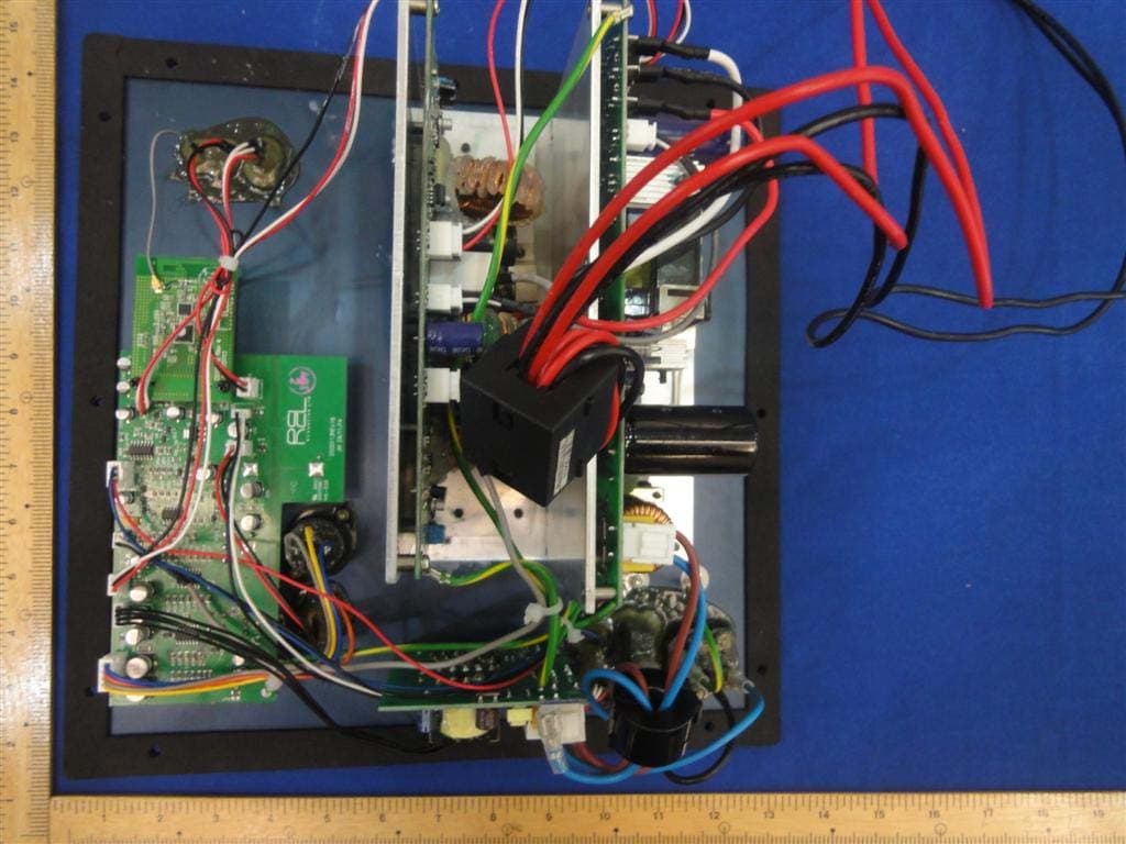
2AATQS212SUB
Apr 26, 2015Amplifier
Equipment Class
DXX - Part 15 Low Power Communication Device Transmitter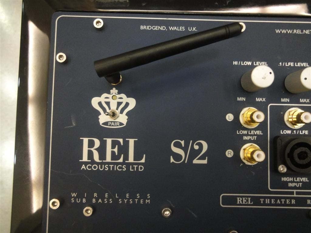
2AATQS2SUB
Apr 08, 2015Amplifier
Equipment Class
DXX - Part 15 Low Power Communication Device Transmitter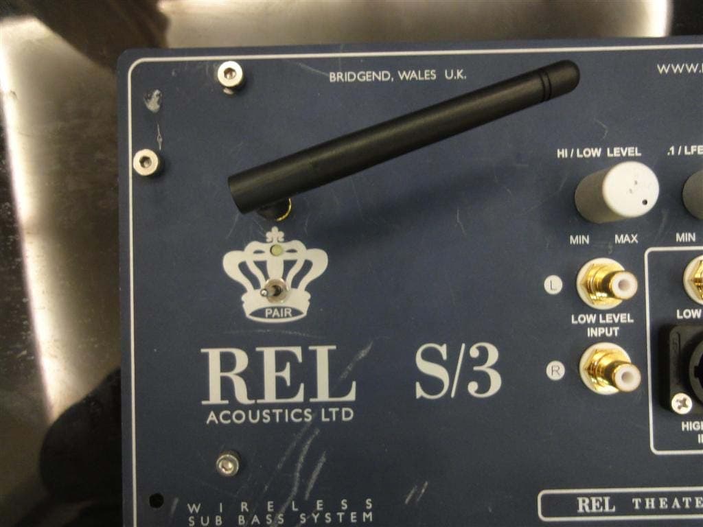
2AATQS3-S5SUB
Apr 07, 2015Amplifier
Equipment Class
DXX - Part 15 Low Power Communication Device Transmitter