2AAZPDC7REMOTE CONTROL
Carewell Electric Technology (Zhongshan) Co., Ltd.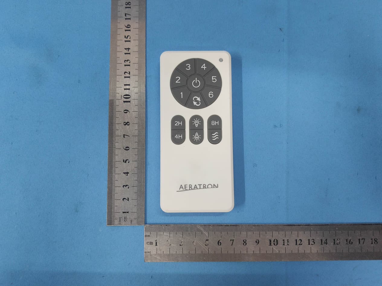
Click to zoom
Application Details
- Equipment Class
- DSC - Part 15 Security/Remote Control Transmitter
- Date of Grant
- Nov 10, 2020
- Application Purpose
- Original Equipment
- Date of Application
- Nov 05, 2020
- Equipment Note
- REMOTE CONTROL
- Frequency Range
- 433.92000000 - 433.92000000
- Country
- China
Documents & Files
Document Text
Text extracted from the exhibit documents filed with the FCC. Open a document above to read the original.
Users Manual
DC PO WER CEILING FAN REMOTE CONTROL MANUAL □INSTALLATION INSTRUCTIONS NO TE: T his unit is to be used for the control of DC power ceiling fan and in an AC120V 60Hz pow er suppl y only. Output Power: 50W (Max.) for motor and 30W (Max.) for LED light. Important: Using a full range dimmer switch (not included) to control fan speed will damage the fan. To reduce the risk of fire or electrical shock, do not use a full range dimmer switch to control fan speed. 1. Switch power off at fuse box or circuit breaker before you begin installing the fan. 2. M ake wiring connections as indicated Fig. 1. 3. Launch distance for remote control: about 10m. 4. T he remote code setting process: Ste p: 1 Open the remote battery cover and install DC1.5V/AAA 2pcs alkaline battery, with the fan power off. (Fig. 2) Step: 2. Within 30 seconds of restring power to the fan, you must use a ball pen or tool to press “Learn” button about 2 seconds. Once the receiver has detected the frequency, the receiver will make sound, Bi once. This will indicate the receiver has learned the frequency that was previously selected on the transmitter. FIG. 2 Note: After the AC power is on, do not press any other button on the transmitter before setting learning. Doing so will cause the procedure to fail. After completing the steps above, you should be able to operate the ceiling fan and light. If the fan is not responding to the transmitter, please turn the power off to the receiver. And repeat step 2. Fi g. 1 Fi g. 2 LIGHT FUNCT ION SELECT SWITCH If installed energy light onto ceiling fan, please slide the di p switch , light function select switch, to “O” position. If installed dimmable LED light onto ceiling fan, please slide the “light function select switch” to “D” position. (Fig. 2) □FUCNCTIONS OF REMOTE CONTROL: (Fig. 3) T urn off the ceiling fan. Fan speed: Press and release immediately to turn on and set fan speed. (6 is for the highest fan speed) Li ght button: ON/OFF- Press and release immediately to turn on or off light. DIMMER-Press and hold to dim or brighten light to the desired level and release. (LE D only and light function select switch on dimmer position.) Sleep Timer: :Th e fan will turn off after 2 hours automatically. :Th e fan will turn off after 4 hours automatically. :The fan will turn off after 8 hours automatically. Na tural breeze: Fan speed will modulate to simulate a natural breeze. Re verse button: Press and release immediately to set fan direction. The fan runs counterclockwise. Airflow will provide a downward cooling breeze. The fan runs clockwise. Airflow will force warm air downward without a noticeable breeze. When you press transmitter button, the receiver will m ake sound, Bi, once as receiving setting signal. If the red LED indicator of transmitter is not working as you pressing button, you need to change and use new batteries. FIG . 3 □INST ALLING WALL MOUNTED HOLDER Att ach wall mounted holder using the two provided screws. (Fig. 4) Fi g. 4 FCC Statement This equipment has been tested and found to comply with the limits for a Class B digital device, pursuant to Part 15 of the FCC Rules. These limits are designed to provide reasonable protection against harmful interference in a residential installation. This equipment generates uses and can radiate radio frequency energy and, if not installed and used in accordance with the instructions, may cause harmful interference to radio communications. However, there is no guarantee that interference will not occur in a particular installation. If this equipment does cause harmful interference to radio or television reception, which can be determined by turning the equipment off and on, the user is encouraged to try to correct the interference by one or more of the following measures: -- Reorient or relocate the receiving antenna. -- Increase the separation between the equipment and receiver. -- Connect the equipment into an outlet on a circuit different from that to which the receiver is connected. -- Consult the dealer or an experienced radio/TV technician for help. Changes or modifications not expressly approved by the party responsible for compliance could void the user's authority to operate the equipment. This device complies with Part 15 of the FCC rules. Operation is subject to the following two conditions: 1) this device may not cause harmful interference, and 2) this device must accept any interference received, including interference that may cause undesired operation.
Cover Letter(s)
DATE : 2020-11-05 Equipment Autorisation Division Federal Communications Commission 7435 Oakland Mills Road Columbia, MD 21046 FCC ID: 2AAZPDC7 Product Name: REMOTE CONTROL Request for Confidentiality To Whom It May Concern, Pursuant to the provisions of the Commission’s rules Title 47 Sections §0.457 and §0.459, we are requesting the Commission to withhold the following attachment(s) as confidential documents from public disclosure indefinitely. These documents contain detailed system and equipment descriptions and are considered as proprietary information in operation of the equipment. The public disclosure of these documents might be harmful to our company and would give competitors an unfair advantage in the market. Schematic Diagram Block Diagram Operational Description In additional to above mentioned documents, in order to comply with the marketing regulations in Title 47 CFR §2.803 and the importation rules in Title 47 CFR §2.1204, while ensuring that business sensitive information remains confidential until the actual marketing of newly authorized devices, we request Short Term Confidentiality of the following attachment(s); External Photos Test Setup Photos Internal Photos User Manual For 45 days, pursuant to Public Notice DA 04-1705. OR For 180 days pursuantto KDB 726920 D01. It is our understanding that all measurement test reports, FCC ID label format and correspondence during the certification review process cannot be granted as confidential documents and this information will be available for public review once the grant of equipment authorization is issued. Signature: Name: ALLEN XU Title: Manager Company: Carewell Electric Technology (Zhongshan) Co., Ltd.
External Photos
Test Model No.: DC7
ID Label/Location Info
MODEL: DC7 FCC ID:2AAZPDC7 THIS DEVICE COMPLIES WITH PART 15 OF THE FCC RULES. OPERATION IS SUBJECT TO T HE FOLLOWING T WO CONDITIONS: (1)T HIS DEVICE INTERFERENCE A ND MAY NOT CAUSE HARMFUL. (2)T HIS DEVICE MUST A CCEPT A NY INTERFERENCE RECEIVED. INCLUDING INTERFERENCE T HAT MAY CAUSE SIZE: 30*20MM UNDESIRED OPERATION 银底黑字 MODEL: DC7 IC: 11037A-DC7 THIS DEVICE COMPLIES WITH PART 15 OF THE FCC RULES. OPERATION IS SUBJECT TO T HE FOLLOWING T WO CONDITIONS: (1)T HIS DEVICE INTERFERENCE A ND MAY NOT CAUSE HARMFUL. (2)T HIS DEVICE MUST A CCEPT A NY INTERFERENCE RECEIVED. INCLUDING INTERFERENCE T HAT MAY CAUSE UNDESIRED OPERATION Carewell Electric Technology (Zhongshan) Co., Ltd
ID Label/Location Info
Label location
Internal Photos
Test Model No.: DC7
RF Exposure Info
RF Exposure evaluation According to 447498 D01 General RF Exposure Guidance v05 The 1-g and 10 -g SAR test exclusion thresholds for 100 MHz to 6 GHz at test separation distances≤ 50 mm are determined by: [(max. power of channel, including tune-up tolerance, mW)/(min. test separation distance, mm)] ·[√f(GHz)] ≤ 3.0 for 1-g SAR and ≤ 7.5 for 10- g extremity SAR, where f(GHz) is the RF channel transmit frequency in GHz Power and distance are rounded to the nearest mW and mm before calculation The result is rounded to one decimal place for comparison eirp = pt x gt = (EXd) 2 /30 where: pt = transmitter output power in watts, gt = numeric gain of the transmitting antenna (unitless), E = electric field strength in V/m, --- 10 ((dBuV/m )/20) /10 6 d = measurement distance in meters (m)---3m Sopt = (EXd) 2 /30 x gt Ant gain= 0dBi ; so Ant numeric gain=1 Field strength =58.59 dBuV/m @3m So Pt={ [10 (58.59 /20) /10 6 x3] 2 /30x1}x1000 mW = 0.0002 mW So ( 0.0002 mW/5mm)x √0.43392 GHz = 0.000026 < 3 Then SAR evaluation is not required
Test Report
Global United Technology Services Co., Ltd. Report No.: GTS202010000160F01 Authorized Signature: Robinson Luo Laboratory Manager This results shown in this test report refer only to the sample(s) tested, this test report cannot be reproduced, except in full, without prior written permission of the company. The report would be invalid without specific stamp of test institute and the signatures of compiler and approver. Page 1 of 19 Cover Page TEST REPORT Applicant: Carewell Electric Technology (Zhongshan) Co., Ltd. Address of Applicant: Torch Development Zone, No.2, Ouya Road, Zhongshan, Guangdong, China Manufacturer/Factory: Carewell Electric Technology (Zhongshan) Co., Ltd. Address of Manufacturer/Factory: Torch Development Zone, No.2, Ouya Road, Zhongshan, Guangdong, China Equipment Under Test (EUT) Product Name: REMOTE CONTROL Model No.: DC7 FCC ID: 2AAZPDC7 Applicable standards: FCC CFR Title 47 Part 15 Subpart C Section 15.231 Date of sample receipt: October 26, 2020 Date of Test: October 27, 2020-November 05, 2020 Date of report issued: November 05, 2020 Test Result : PASS * * In the configuration tested, the EUT complied with the standards specified above. Report No.: GTS202010000160F01 Global United Technology Services Co., Ltd. No.123-128, Tower A, Jinyuan Business Building, No.2, Laodong Industrial Zone, Xixiang Road, Baoan District, Shenzhen, Guangdong, China 518102 Telephone: +86 (0) 755 2779 8480 Fax: +86 (0) 755 2779 8960 Page 2 of 19 2 Version Version No. Date Description 01 November 05, 2020 Original Prepared By: Date: November 05, 2020 Project Engineer Check By: Date: November 05, 2020 Reviewer Report No.: GTS202010000160F01 Global United Technology Services Co., Ltd. No.123-128, Tower A, Jinyuan Business Building, No.2, Laodong Industrial Zone, Xixiang Road, Baoan District, Shenzhen, Guangdong, China 518102 Telephone: +86 (0) 755 2779 8480 Fax: +86 (0) 755 2779 8960 Page 3 of 19 3 Contents Page 1 COVER PAGE ...........................................................................................................................................1 2 VERSION ...................................................................................................................................................2 3 CONTENTS ...............................................................................................................................................3 4 TEST SUMMARY ......................................................................................................................................4 4.1 MEASUREMENT UNCERTAINTY .............................................................................................................4 5 GENERAL INFORMATION .......................................................................................................................5 5.1 GENERAL DESCRIPTION OF EUT ..........................................................................................................5 5.2 TEST MODE .........................................................................................................................................6 5.3 DESCRIPTION OF SUPPORT UNITS ........................................................................................................6 5.4 TEST FACILITY ....................................................................................................................................6 5.5 TEST LOCATION ..................................................................................................................................6 5.6 OTHER INFORMATION REQUESTED BY THE CUSTOMER ..........................................................................6 5.7 ADDITIONAL INSTRUCTIONS ..................................................................................................................6 6 TEST INSTRUMENTS LIST ......................................................................................................................7 7 TEST RESULTS AND MEASUREMENT DATA .......................................................................................9 7.1 ANTENNA REQUIREMENT ......................................................................................................................9 7.2 RADIATED EMISSION METHOD ............................................................................................................10 7.2.1 Field Strength of The Fundamental Signal ..................................................................................12 7.2.2 Spurious Emissions .....................................................................................................................13 7.3 20DB OCCUPY BANDWIDTH ...............................................................................................................17 7.4 DWELL TIME .....................................................................................................................................18 8 TEST SETUP PHOTO .............................................................................................................................19 9 EUT CONSTRUCTIONAL DETAILS .......................................................................................................19 Report No.: GTS202010000160F01 Global United Technology Services Co., Ltd. No.123-128, Tower A, Jinyuan Business Building, No.2, Laodong Industrial Zone, Xixiang Road, Baoan District, Shenzhen, Guangdong, China 518102 Telephone: +86 (0) 755 2779 8480 Fax: +86 (0) 755 2779 8960 Page 4 of 19 4 Test Summary Test Item Section in CFR 47 Result Antenna Requirement 15.203 Pass Conduction Emission 15.207 N/A Field strength of the Fundamental Signal 15.231 (b) Pass Spurious Emissions 15.231 (b)/15.209 Pass 20dB Bandwidth 15.231 (c) Pass Dwell Time 15.231 (a)1 Pass Pass: The EUT complies with the essential requirements in the standard. N/A: Not applicable. 4.1 Measurement Uncertainty Test Item Frequency Range Measurement Uncertainty Notes Radiated …
Text truncated - open the document above for the full version.
Test Setup Photos
Test Model No.: DC7 Radiated Emission
Contact Information
Applicant
ALLEN XU(Manager)
Test Firm
Global United Technology Services Co. Ltd.Robinson Lo
Technical Specifications
| # | Rule Parts | Frequency Range | Power Output |
|---|---|---|---|
| 1 | 15.231 | 433.92 MHz - 433.92 MHz | - |
Other Applications from Carewell Electric Technology (Zhongshan) Co., Ltd.
2AAZPCT0311YB
Jan 20, 2024DC power ceiling fan remote control
Equipment Class
DSC - Part 15 Security/Remote Control Transmitter
2AAZPHD3T
Apr 27, 2021REMOTE CONTROL
Equipment Class
DSC - Part 15 Security/Remote Control Transmitter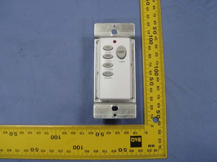
2AAZPFAN55T
Jan 27, 2016REMOTE CONTROL
Equipment Class
DSC - Part 15 Security/Remote Control Transmitter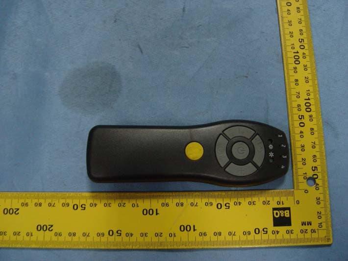
2AAZPFAN61T4SP
Sep 27, 2015REMOTE CONTROL
Equipment Class
DSC - Part 15 Security/Remote Control Transmitter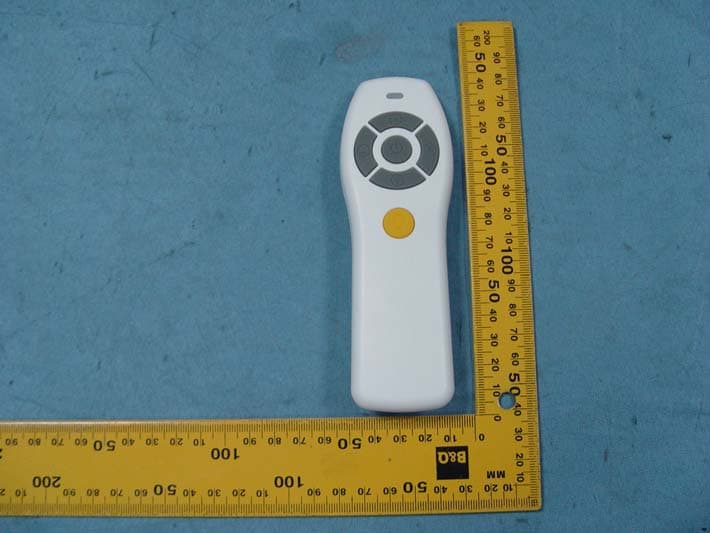
2AAZPFAN61T3SP
Sep 13, 2015REMOTE CONTROL
Equipment Class
DSC - Part 15 Security/Remote Control Transmitter