2AB3B-RECEIVERLivid USB Receiver 1
Viditar Inc.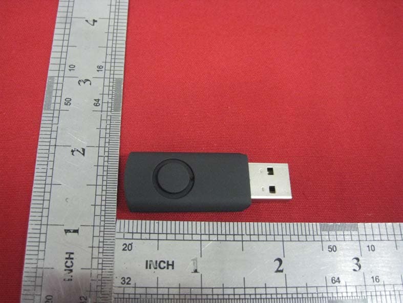
Click to zoom
Application Details
- Equipment Class
- DXX - Part 15 Low Power Communication Device Transmitter
- Date of Grant
- May 11, 2014
- Application Purpose
- Original Equipment
- Date of Application
- May 11, 2014
- Equipment Note
- Livid USB Receiver 1
- Frequency Range
- 2402.00000000 - 2480.00000000
- Company
- Viditar Inc.
- Country
- United States
Documents & Files
Document Text
Text extracted from the exhibit documents filed with the FCC. Open a document above to read the original.
Users Manual
Quick Start Guide www.lividinstruments.com Guitar Wing Quick Start Guide Thanks for purchasing the Guitar Wing™ from Livid Instruments. We’ve designed Guitar Wing to encourage you to experiment and expand your creative possibilities. We can’t wait to see and hear what you do with it! For additional resources and instruction on using your Guitar Wing please visit lividinstruments.com/guitarwing. Guitar Wing™, WingFX™, and Livid Instruments™ are registered trademarks of Livid Instruments Inc. Designed in Austin, TX USA. © 2014 Livid Instruments Inc., Viditar Inc., Patents Pending, All Rights Reserved Contents In the Box 2 Product Registration 2 Quickstart 2 Fitting your Guitar Wing 2 Swivel 3 Thickness 3 Safety 3 Using The Wing 4 Controls 4 Other Controls 5 Connections 5 Charging and Power 5 Wireless Useage 6 Pairing your Guitar Wing with the USB receiver 6 WingFX™ 6 Controls Overview 7 Using the Editor 8 MIDI Map 8 Default MIDI settings 8 Support 8 Warranty 9 Certification and Compliance 11 1 In the Box ● Guitar Wing ● USB receiver ● Charging cable ● Safety strap ● Spacer shim ● User guide Product Registration Thank you for purchasing the Guitar Wing from Livid Instruments. We hope this new device and concept will inspire you with new possibilities for creative expression. Please register your device by going to lividinstruments.com/register to make sure you get the latest updates, news, and tips for using your Guitar Wing. Quickstart The Guitar Wing is a fully customizable control surface but customizing the controls and using the Wing Editor is not necessary to start using the Guitar Wing. It’s plug-and-play: just follow this Quickstart Guide to get you playing in minutes. 1. Power on the Guitar Wing using the slide switch on the side of the device 2. Connect the wireless USB Receiver to your computer or tablet 3. Clamp the Guitar Wing on your guitar or bass and position the Safety Strap 4. Check your software’s MIDI preferences or settings to choose Guitar Wing as your USB MIDI device 5. Start using your Guitar Wing! Fitting your Guitar Wing The Guitar Wing is designed to fit a wide variety of Guitars and Basses ranging from 1.25”(30mm) to 1.75”(45mm) Some setup may be required 2 to get the Guitar Wing to fit your exact guitar model. We have designed the device to both swivel and change thickness using the space shim. Swivel The Guitar Wing is designed to fit to the guitar with the lower arm touching the inside curve of the guitar cut-out. In this position, you can sit down with the guitar and the Guitar Wing will not move as it rests against your leg. The top housing should match the angle of the horn. To adjust the angle the Guitar Win sits at, flip the Guitar Wing over so the controls are face down. Where the arm is mounted to the housing, you will see three position holes. The Guitar Wing ships in position ‘A.’ You can adjust the mounting angle by removing the position screw and rotating the arm to either position ‘B’ or ‘C.’ Once it’s properly positioned, replace the position screw in the new position hole. Be careful not to over-tourque the poistion screw when adjusting the swivel. Thickness The Guitar Wing ships with a spacer shim that is designed to keep the Wing securely clamped to most guitars. For guitar bodies 1.25” (32mm) and thinner, you will need to attach the included thicker shim. There are four screws from the bottom of the lower shim that hold the shim on. Remove all four screws and re-attach the taller shim to get a tighter clamping assembly. Safety The Guitar Wing is designed to stay clamped to the guitar and move as little as possible. To protect against damage and drops during more active performances, there are two strap anchors and an elastic safety strap included. It is recommended that you loop the safety strap on the bottom anchor and leave it attached. When you place the Guitar Wing on the guitar and have it in the correct position, stretch the safety strap over the guitar and hook the end into the upper strap anchor. 3 Using The Wing Controls Default behavior of Guitar Wing’s controls are described below. Use the Guitar Wing Editor to change how different controls respond. A. Pads - The Guitar Wing has five pressure/velocity sensitive pads that send MIDI Note messages and CC afterpressure messages. By default, the smallest pad located near the horn of the controller is used to turn the Motion Control on and off. B. Function Buttons - The four function buttons act as on/off switches and send note on/off messages when pressed. These are not pressure sensitive. C. Direction Buttons - The two directional buttons act as on/off switches and send note on/off messages when pressed. D. Side Buttons - The four function buttons act as on/off switches and send note on/off messages when pressed. 4 E. Touch Fader - The long touch fader sends CC messages for position, and note on/off messages when touched. F. Dual Touch Fader - The dual-touch fader acts as two faders and sends CC messages for position and note on/off messages when touched. Other Controls ● Accelerometer (Motion Control) - The accelerometer sends CC messages when enabled. To use the accelerometer or Motion Control, simply tilt the device up and down or lean forward when enabled to send these messages. By default, the accelerometer is enabled by toggling the fifth pad at the end of the horn of the instrument. ● Power Switch - The power switch turns the Guitar Wing on and off. Turn the Guitar Wing off when not in use to conserve battery life. ● Strap Anchor - Connect the safety strap to the strap anchor for added stability when performing. Connections ● Charging Port - The Guitar Wing is charged with a micro USB cable and can be charged using any 5V USB charging source, including the USB port on your computer. The Charging Port does not act as a data transfer between the computer and the device, it is used for charging only. ● Wireless Receiver - The USB wireless receiver send messages back and forth to the…
Text truncated - open the document above for the full version.
External Photos
1 of 2 ATT Product Service Co., Ltd. (CBTL Lab of UL/Demko) No. 3, ChangLianShan Industrial Park, ChangAn Town, DongGuan City, GuangDong, China. Phone: 86-769-8509 8000; Fax: 86-769-8509 8777 E-mail:[email protected] External photos 2 of 2 ATT Product Service Co., Ltd. (CBTL Lab of UL/Demko) No. 3, ChangLianShan Industrial Park, ChangAn Town, DongGuan City, GuangDong, China. Phone: 86-769-8509 8000; Fax: 86-769-8509 8777 E-mail:[email protected]
ID Label/Location Info
Lable location
Internal Photos
1 of 2 ATT Product Service Co., Ltd. (CBTL Lab of UL/Demko) No. 3, ChangLianShan Industrial Park, ChangAn Town, DongGuan City, GuangDong, China. Phone: 86-769-8509 8000; Fax: 86-769-8509 8777 E-mail:[email protected] Internal Photos 2 of 2 ATT Product Service Co., Ltd. (CBTL Lab of UL/Demko) No. 3, ChangLianShan Industrial Park, ChangAn Town, DongGuan City, GuangDong, China. Phone: 86-769-8509 8000; Fax: 86-769-8509 8777 E-mail:[email protected]
RF Exposure Info
RF Exposure evaluation According to 447498 D01 General RF Exposure Guidance v05 The 1-g and 10-g SAR test exclusion thresholds for 100 MHz to 6 GHz at test separation distancesİ 50 mm are determined by: [(max. power of channel, including tune-up tolerance, mW)/(min. test separation distance, mm)] g[Ĝf(GHz)]İ 3.0 for 1-g SAR and İ 7.5 for 10-g extremity SAR, where ǂf(GHz) is the RF channel transmit frequency in GHz ǂ Power and distance are rounded to the nearest mW and mm before calculation ǂThe result is rounded to one decimal place for comparison eirp = pt x gt = (EXd) 2 /30 where: pt = transmitter output power in watts, gt = numeric gain of the transmitting antenna (unitless), E = electric field strength in V/m, --- 10 ((dBuV/m)/20) /10 6 d = measurement distance in meters (m)---3m Sopt = (EXd) 2 /30 x gt Field strength = 70.35dBuV/m @3m Ant gain =0dBi;so Ant numeric gain=0 So pt={ [10 ( ̨ 70.35 ̨ ̨ /20) /10 6 x3] 2 /30x ̨}x1000 mW =0.0033mW So (0.0033mW/5mm)x Ĝ2.402GHz =0.001<3 Then SAR evaluation is not required 1 1 88.25 88.25dBuV/m @3m =0.2mW (0.2mW/5mm)x Ĝ2.402GHz =0.06<3
Test Report
Report No.: 14EAB03052 211 of 21 ATT Product Service Co., Ltd. (CBTL Lab of UL/Demko) No. 3, ChangLianShan Industrial Park, ChangAn Town, DongGuan City, GuangDong, China. Phone: 86-769-8509 8000; Fax: 86-769-8509 8777 E-mail:[email protected] FCC CERTIFICATION TEST REPORT FOR FCC ID: 2AB3B-RECEIVER Report Reference No....................... : 14EAB03052 21 Date of issue.................................... : 2014-04-11 Testing Laboratory........................... : ATT Product Service Co., Ltd. Address ............................................ : No. 3, ChangLianShan Industrial Park, ChangAn Town, DongGuan City, GuangDong, China. Applicant’s name.............................. : Viditar Inc.. Address ............................................ : 3108 Industrial Terrace Austin, TX78758 USA Manufacturer.................................... : Season Components Company Ltd. Test specification: Test item description........................ : Livid Guitar Wing Trade Mark....................................... : Model/Type reference .................... : Livid USB Receiver 1 Ratings ............................................. : 5Vdc,12mA Responsible Engineer Approved by ˄Bin Jiang/ Engineer˅˄Tomy Wu /EMC Manager˅ Report No.: 14EAB03052 112 of 21 ATT Product Service Co., Ltd. (CBTL Lab of UL/Demko) No. 3, ChangLianShan Industrial Park, ChangAn Town, DongGuan City, GuangDong, China. Phone: 86-769-8509 8000; Fax: 86-769-8509 8777 E-mail:[email protected] TABLE OF CONTENTS TEST REPORT DECLARE................................................................................................................................4 1.Summary of test Standards and results........................................................................................................ 5 2.General test information.................................................................................................................................. 6 2.1 ACCREDITATIONS.................................................................................................................................... 6 2.2 Description of EUT...................................................................................................................................... 6 2.3 Accessories of EUT.................................................................................................................................... 6 2.4 Assistant equipment used for test............................................................................................................ 6 2.5 Block diagram of EUT configuration for test........................................................................................... 7 2.6 Test environment conditions..................................................................................................................... 7 2.7 Measurement uncertainty.......................................................................................................................... 7 3. 20dB Bandwidth............................................................................................................................................ 8 3.1 Test equipment............................................................................................................................................ 8 3.2 Block diagram of test setup....................................................................................................................... 8 3.3 Applicable Standard................................................................................................................................... 8 3.4 Test Procedure............................................................................................................................................ 8 3.5 Test Result................................................................................................................................................... 9 3.6 Original test data......................................................................................................................................... 9 4. Radiated emission....................................................................................................................................... 11 4.1 Test equipment.......................................................................................................................................... 11 4.2 Block diagram of test setup..................................................................................................................... 11 4.3 Limit............................................................................................................................................................. 12 4.4 Test Procedure .............................................................................................................................................. 14 4.5 Test result.................................................................................................................................................. 14 5. OUT OF BAND EMISSION (50dB ATTENUATION)................................................ 䫭䇃ʽᅮНкᅤDŽ 5.1 Test equipment..........................................................................................................䫭䇃ʽᅮНкᅤDŽ 5.2 Block diagram of test setup.....................................................................................䫭䇃ʽᅮНкᅤDŽ 5.3 Applicable Standard.................................................................................................䫭䇃ʽᅮНкᅤDŽ 5.4 Test Procedure..........................................................................................................䫭䇃ʽᅮНкᅤDŽ 5.5 Test result..................................................................................................................䫭䇃ʽᅮНкᅤDŽ 6. Antenna Requirements.........................................................................................................................…
Text truncated - open the document above for the full version.
Test Setup Photos
1 of 2 ATT Product Service Co., Ltd. (CBTL Lab of UL/Demko) No. 3, ChangLianShan Industrial Park, ChangAn Town, DongGuan City, GuangDong, China. Phone: 86-769-8509 8000; Fax: 86-769-8509 8777 E-mail:[email protected] Test setup photograph 2 of 2 ATT Product Service Co., Ltd. (CBTL Lab of UL/Demko) No. 3, ChangLianShan Industrial Park, ChangAn Town, DongGuan City, GuangDong, China. Phone: 86-769-8509 8000; Fax: 86-769-8509 8777 E-mail:[email protected]
Contact Information
Applicant
Travis Redding
Test Firm
ATT Product Service Co., Ltd.Dick Lian
Technical Specifications
| # | Rule Parts | Frequency Range | Power Output |
|---|---|---|---|
| 1 | 15C | 2.40 GHz - 2.48 GHz | - |
Other Applications from Viditar Inc.
2AB3B-GUITAR-WING
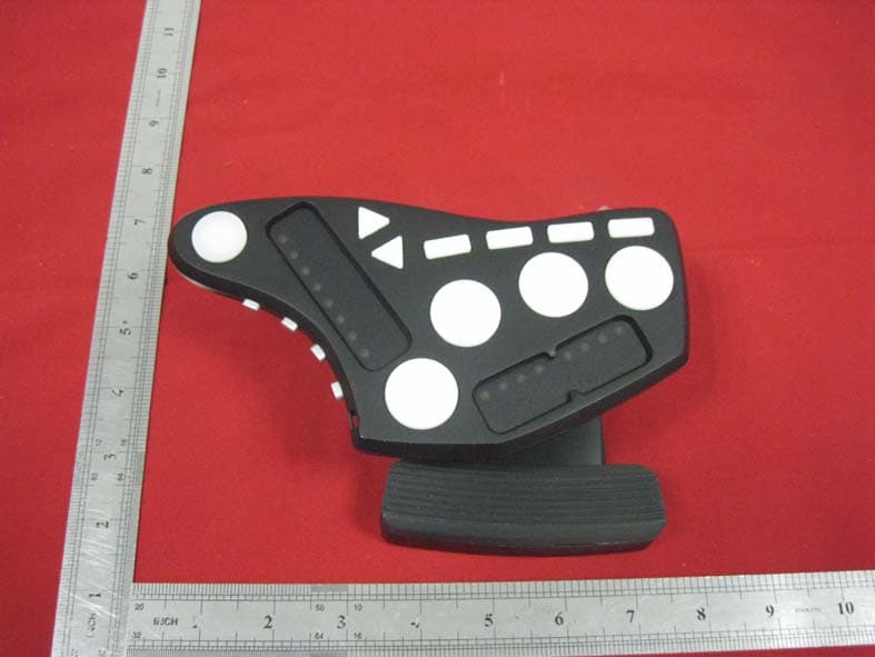
May 09, 2014Livid Guitar Wing 1
Equipment Class
DXX - Part 15 Low Power Communication Device Transmitter