2AB3P-CTSR12250033CTS Tank Alarm Display
Husky Corporation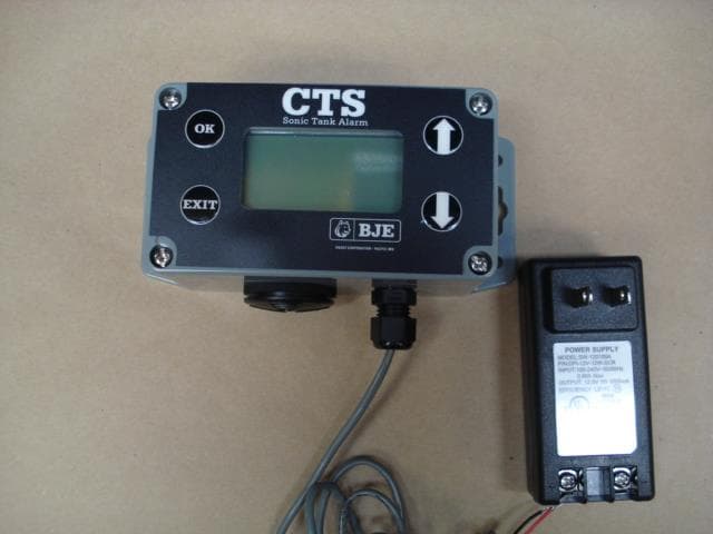
Click to zoom
Application Details
- Equipment Class
- DXX - Part 15 Low Power Communication Device Transmitter
- Date of Grant
- Aug 03, 2014
- Application Purpose
- Original Equipment
- Date of Application
- Aug 03, 2014
- Equipment Note
- CTS Tank Alarm Display
- Frequency Range
- 2425.00000000 - 2475.00000000
- Company
- Husky Corporation
- Country
- United States
Documents & Files
Document Text
Text extracted from the exhibit documents filed with the FCC. Open a document above to read the original.
Users Manual
• The sensor will measure tank depths from 8” to 300” (20 to 760 cm) high. • LED alarm will display tank levels in English or metric units. • Alarm displays tank level height and % full. • The alarm will warn if the tank fluid level is “low” or “high” using an audible alert and lighted display. • Customer can silence audible alert once high or low levels have been alerted. • Allows customer to continue filling or emptying the tank past alarm level. • Alarm/Sensor range inside a building is 30 ft. • The alarm can be programmed to display up to six sensors. • Alarm and sensor are powered by standard 110 VAC/12 VDC power supply. CTS Tank Alarm MODEL NO. DESCRIPTION SHIPPING WEIGHT LBS (KG) 10856 CTS Remote Tank 4.0 (1.8) CTS Tank Alarm Alarm for use with oil, waste oil, diesel fuel, antifreeze, and other fluids with a low flash point. TANK GAUGES AND ALARMS 3-12 Rev B 4/14 TANK GAUGES AND ALARMS Dimensions 2325 Husky Way • Pacific, MO 63069 (800) 325-3558 • Fax (636) 825-7300 www.husky.com • [email protected] MADE IN THE U.S.A. Rev B 4/14 CTS Tank Alarm Alarm for use with oil, waste oil, diesel fuel, antifreeze, and other fluids with a low flash point. 3-12 Accessories MODEL NO. DESCRIPTION 10857 CTS Remote Tank Sensor Rev. 4-12 4.6”/ 117 mm 2.5”/ 64 mm 2.5”/ 64 mm 4.6”/ 117 mm
Users Manual
Note: This is a Class A ITE device which is intended primarily for use in an environment where the use of broadcast radio and television receivers may be expected within a distance of 10 m. This equipment has been tested and found to comply with the limits for a Class A digital device, pursuant to part 15 of the FCC Rules. These limits are designed to provide reasonable protection against harmful interference when the equipment is operated in a commercial environment. This equipment generates, uses, and can radiate radio frequency energy and, if not installed and used in accordance with the instruction manual, may cause harmful interference to radio communications. Operation of this equipment in a residential area is likely to cause harmful interference in which case the user will be required to correct the interference at his own expense. Note: This devise shall be installed greater than 8" (20 cm) from contact with people. Remarque: Cet appareil doit être installé plus de 8" (20 cm) entre le contact avec les gens. Note: This device complies with Industry Canada license-exempt RSS standard(s). Operation is subject to the following two conditions: (1) this device may not cause interference, and (2) this device must accept any interference, including interference that may cause undesired operation of the device. Remarque: Cet appareil est conforme aux normes Industry Canada exemptes de license RSS standard(s). Son fonctionnement est soumis aux deux conditions suivantes: (1) cet appareil ne doit pas provoquer d'interférences et (2) cet appareil doit accepter toute interférence, y compris les interférences susceptibles de provoquer un fonctionnement indésirable. Note: The tank sensor will measure tank depths from 8" to 300" (20 cm to 760 cm) high. CTS TANK ALARM WARNING Never use with gasoline or highly flammable liquids. Not to be used with any other gauge or monitor Husky Corporation • 2325 Husky Way • Pacific, MO 63069 • Phone: (800) 325-3558 • Fax: (636) 825-7300 • www.husky.com Page 1 009371-1 7/2014 INSTALLATION INSTRUCTIONS CTS TANK ALARM Model 10856 & 10857 Recommended Installation, Maintenance and Inspection Instructions Important safety InstructIons - save these InstructIons In a readIly accessIble locatIon. 1. Component Installation CTS Sonic Tank Alarm Sensor Mount the sensor into the 2" NPT tank bung hand tight - do not overtighten. Do not use thread lock adhesive as this may damage the Tank Alarm Sensor. The CTS Sensor must be mounted within 2 degrees from perpendicular to the surface of the fluid. A level that measures degrees should be used. Place the level on the top of the pipe fitting on the tank. If outside the 2 degree specification, the fitting should be changed. Husky ® recommends that the height of the tank fitting should not exceed 1/2" (1.27 cm). Also, the taller the tank, the more critical the 2 degrees become. Note: The CTS Sonic Tank Alarm Sensor will not read properly if: CTS Sensor is tilted more than 2 degree from the surface of the tank liquid. CTS Sensor is mounted next to the tank wall or in a corner. If there is any structural bracing or obstruction between the CTS Sensor and the surface of fluid in tank. Note: Do not install the CTS Sensor in the tank's fill port. Repeated removal of the CTS sensor will damage the unit and void the warranty. Plug the transformer into a non-switched 24 hour hot 115v outlet. CTS Sonic Tank Alarm Receiver Securely (not permanently) mount receiver to wall within 30 feet (9.1m) of alarm sensor. Plug the transformer into a non-switched 24 hour hot 115v outlet. Remove protective coating over display. 2. Programming the receiver The receiver will ask to choose display unit. Press "ok" for English. Press "exit" for metric. The receiver will recognize an operating sensor signal and ask to add to receiver. Press "ok" for yes. Press "exit" for no. *Enter personal tank name. Choose 10 characters from letter, numbers, or spaces. Press "ok" after each selection. Enter tank depth. Choose depth from 8" to 300" (20 cm to 760 cm). Press "ok" after each selection. Select alarm type. Scroll down to settings both, high, or low and press "ok." Note: If the alarm setting is to be changed, complete the tank programming and erase the tank information under section 4 and repeat entering personal tank name under section 2. The receiver will display tank label, level and percentage. Note: The receiver will continue to search for operating tank sensor signals and ask to add to display until all sensors are added or the tank sensor search mode is turned off. 3. Alarm mode. If tank depth is greater than 78 in (199 cm) and fluid level percentage is greater than 90 or less than 11, then the siren will sound and display will flash red. If tank depth is greater than 78 in (199 cm) and fluid level percentage is greater than 87 or less than 13, then the display will flash red at 30 second inter- vals. If tank depth is less than 79 in (200 cm) and fluid level percentage is greater than 75 or less than 11, then the siren will sound and display will flash red. If tank depth is less than 79 in (200 cm) and fluid level percentage is greater than 72 or less than 13, then the display will flash red at 30 second intervals. To silence the siren, press the "ok" button and the siren will silence. The display will continue to flash red until the tank level is within the above ranges. 4. To change settings: Press "exit" turn to function menu. The menu screen will display receiver firmware version, tank, units, display search and channel. Scroll up or down to the appropriate function using the "up" or "down" arrows and press "ok". To erase tank information, press "ok" on tank menu. Scroll down to desired tank using the "down" arrow and press "ok". The receiver will ask to "erase tank selection". Press "ok" to erase. Pressing "exit" will reset tank depth. The receiver will ask to choose display units. Press "ok" for English. Press "exit" for metric. Press "exit" to return …
Text truncated - open the document above for the full version.
RF Exposure Info
. Preliminary (06/07) © 2007. All Rights Reserved. Dualband WLAN Ceramic Chip Antenna Groun d c leared under a ntenna 1 1.60 x 6.00 mm. P ul se Part Number: W3006 Pulse Finland Oy Takatie 6 90440 K empele, Finland Tel: +358 207 935 500 Fax: +358 207 935 501 www.pulseeng.com/antennas Featur es - Omnidirectional radiation - Lo w - Compact size WxLxH (10.0 x 3.2 x 1.5 mm) - Lo w w eight (240 mg) - Fully SMD compatible - Lead free soldering compatible - T ape and reel packing - RoHS Compliant Product - Single feed point Applications - IEEE 802.11a/b/g - 5 GHz WLAN - 2.4 GHz WLAN - 2.4 GHz ISM Band Systems - ZigBee IEEE 802.15.4 Note: Electrical characteristics depend on test board (GP) size and antenna positioning on GP and Ground Clearance area size. Dualband WLAN Typical performance (testboard size 80 x 37 mm, PWB ground clearance area 11.60 x 6.00 mm) 1.5nH shunt inductor used for impedance matching. Frequency Range [MHz] 2400–2483.5 5150–5850 Max Gain [dBi] 3.2 (peak) 2.7 (band edges) 4.2 (peak) 3.0 (band edges) [%] / [dB] 70 / -1.55 (peak) 65 / -1.85 (band edges) 80 / -0.95 (peak) 70 / -1.55 (band edges) Return loss min. [dB] -8 -10 Impedance [Ω] 50 50 Operating Temperature [°C] -40 to +85 -40 to +85 © 2007. All Rights Reserved. Dualband WLAN Ceramic Chip Antenna Groun d c leared under a ntenna 1 1.60 x 6.00 mm. P ul se Part Number: W3006 Pulse Finland Oy Takatie 6 90440 K empele, Finland Tel: +358 207 935 500 Fax: +358 207 935 501 www.pulseeng.com/antennas Recommended test board layout for electrical characteristic measurement, test board outline size 80 x 37mm Feed line should be designed to match 50 Ω characteristic impedance, depending on PWB material and thickness. Shunt matching inductor, 1.5nH with presented setup. Exact inductor value depends on application. © 2007. All Rights Reserved. Dualband WLAN Ceramic Chip Antenna Groun d c leared under a ntenna 1 1.60 x 6.00 mm. P ul se Part Number: W3006 Pulse Finland Oy Takatie 6 90440 K empele, Finland Tel: +358 207 935 500 Fax: +358 207 935 501 www.pulseeng.com/antennas Typical Electrical Characteristics (T=25 °C) 2,4 GHz Typical Return Loss S11/ impedance, measured on the test board 5GHz Typical Return Loss S11/ impedance, measured on the test board
RF Exposure Info
© 2007. All Rights Reserved. Dualband WLAN Ceramic Chip Antenna Groun d c leared under a ntenna 1 1.60 x 6.00 mm. P ul se Part Number: W3006 Pulse Finland Oy Takatie 6 90440 K empele, Finland Tel: +358 207 935 500 Fax: +358 207 935 501 www.pulseeng.com/antennas 2,4 GHz free space and maximum gain 5 GHz free space and maximum gain © 2007. All Rights Reserved. Dualband WLAN Ceramic Chip Antenna Groun d c leared under a ntenna 1 1.60 x 6.00 mm. P ul se Part Number: W3006 Pulse Finland Oy Takatie 6 90440 K empele, Finland Tel: +358 207 935 500 Fax: +358 207 935 501 www.pulseeng.com/antennas XY -PLANE XZ-PLANEZY -PLANE 2,4 GHz Typical F ree space Radiation Patterns © 2007. All Rights Reserved. Dualband WLAN Ceramic Chip Antenna Groun d c leared under a ntenna 1 1.60 x 6.00 mm. P ul se Part Number: W3006 Pulse Finland Oy Takatie 6 90440 K empele, Finland Tel: +358 207 935 500 Fax: +358 207 935 501 www.pulseeng.com/antennas XZ-PLANE 5 GHz Typical Free space Radiation Patterns ZY -PLANE XY -PLANE
Test Report
MET Laboratories, Inc. Safety Certification - EMI - Telecom Environmental Simulation 914 WEST PATAPSCO AVENUE • BALTIMORE, MARYLAND 21230-3432 • PHONE (410) 354-3300 • FAX (410) 354-3313 33439 WESTERN AVENUE • UNION CITY, CALIFORNIA 94587 • PHONE (510) 489-6300 • FAX (510) 489-6372 3162 BELICK STREET • SANTA CLARA, CA 95054 • PHONE (408) 748-3585 • FAX (510) 489-6372 13301 MCCALLEN PASS • AUSTIN, TEXAS 78753 • PHONE (512) 287-2500 • FAX (512) 287-2513 The Nation’s First Licensed Nationally Recognized Testing Laboratory August 4, 2014 Husky Corporation 2325 Husky Way Pacific, MO 63069 Dear Roger Wiersma, Enclosed is the EMC Wireless test report for compliance testing of the Husky Corporation, CTS Tank Alarm - Display as tested to the requirements of Title 47 of the CFR, Ch. 1 (10-1-06 ed.), Part 15, Subpart B and ICES- 003, ICES-003, Issue 5 August 2012 for a Class B Digital Device, and FCC Part 15 Subpart C and RSS-210, Issue 8, Dec. 2010 for Intentional Radiators. Thank you for using the services of MET Laboratories, Inc. If you have any questions regarding these results or if MET can be of further service to you, please feel free to contact me. Sincerely yours, MET LABORATORIES, INC. Jennifer Warnell Documentation Department Reference: (\Husky Corporation\EMC41433B-FCC249 Rev. 1) Certificates and reports shall not be reproduced except in full, without the written permission of MET Laboratories, Inc. Electromagnetic Compatibility Husky Corporation Cover Page CTS Tank Alarm - Display CFR Title 47, Part 15B, 15.249; RSS-210, Issue 8, Dec. 2010 & ICES-003 MET Report: EMC41433B-FCC249 Rev. 1 © 2014, MET Laboratories, Inc. Page ii of vii DOC-EMC702 6/18/2009 Electromagnetic Compatibility Criteria Test Report for the Husky Corporation CTS Tank Alarm - Display Tested under the FCC Certification Rules contained in Title 47 of the CFR, Parts 15 Subpart B & ICES-003 for Class B Digital Devices & 15.249 Subpart C & RSS-210, Issue 8, Dec. 2010 for Intentional Radiators MET Report: EMC41433B-FCC249 Rev. 1 August 4, 2014 Prepared For: Husky Corporation 2325 Husky Way Pacific, MO 63069 Prepared By: MET Laboratories, Inc. 914 W. Patapsco Ave. Baltimore, MD 21230 Electromagnetic Compatibility Husky Corporation Cover Page CTS Tank Alarm - Display CFR Title 47, Part 15B, 15.249; RSS-210, Issue 8, Dec. 2010 & ICES-003 MET Report: EMC41433B-FCC249 Rev. 1 © 2014, MET Laboratories, Inc. Page iii of vii DOC-EMC702 6/18/2009 Electromagnetic Compatibility Criteria Test Report for the Husky Corporation CTS Tank Alarm - Display Tested under the FCC Certification Rules contained in Title 47 of the CFR, Parts 15 Subpart B & ICES-003 for Class B Digital Devices & 15.249 Subpart C & RSS-210, Issue 8, Dec. 2010 for Intentional Radiators Djed Mouada, Project Engineer Jennifer Warnell Electromagnetic Compatibility Lab Documentation Department Engineering Statement: The measurements shown in this report were made in accordance with the procedures indicated, and the emissions from this equipment were found to be within the limits applicable. I assume full responsibility for the accuracy and completeness of these measurements, and for the qualifications of all persons taking them. It is further stated that upon the basis of the measurements made, the equipment tested is capable of operation in accordance with the requirements of the FCC Rules Parts 15B, 15.249 and Industry Canada standards ICES-003, Issue 5 August 2012, RSS-210, Issue 8, December 2010 under normal use and maintenance. Asad Bajwa, Director, Electromagnetic Compatibility Lab Electromagnetic Compatibility Husky Corporation Report Status CTS Tank Alarm - Display CFR Title 47, Part 15B, 15.249; RSS-210, Issue 8, Dec. 2010 & ICES-003 MET Report: EMC41433B-FCC249 Rev. 1 © 2014, MET Laboratories, Inc. Page iv of vii DOC-EMC702 6/18/2009 Report Status Sheet Revision Report Date Reason for Revision June 25, 2014 Initial Issue. 1 August 4, 2014 Editorial corrections. Electromagnetic Compatibility Husky Corporation Table of Contents CTS Tank Alarm - Display CFR Title 47, Part 15B, 15.249; RSS-210, Issue 8, Dec. 2010 & ICES-003 MET Report: EMC41433B-FCC249 Rev. 1 © 2014, MET Laboratories, Inc. Page v of vii DOC-EMC702 6/18/2009 Table of Contents I. Executive Summary .................................................................................................................................................1 A. Purpose of Test ...................................................................................................................................................2 B. Executive Summary ............................................................................................................................................2 II. Equipment Configuration .......................................................................................................................................3 A. Overview .............................................................................................................................................................4 B. References ...........................................................................................................................................................5 C. Test Site ..............................................................................................................................................................5 D. Description of Test Sample .................................................................................................................................6 E. Equipment Configuration ....................................................................................................................................6 F. Support Equipment .............................................................................................................................................6 G. Ports and Cabling Information ..........................................................…
Text truncated - open the document above for the full version.
Test Setup Photos
Photograph 1. Conducted Emissions, Test Setup Photograph 2. Radiated Emission, Test Setup Photograph 3. Conducted Emissions, 15.207(a), Test Setup Photograph 4. Radiated Spurious Emissions, Test Setup
Contact Information
Applicant
Roger Eugene Wiersma(Product Development Engineer)
Technical Contact
Husky CorporationRoger Eugene Wiersma
[email protected]636-825-7234
2325 Husky Way · Pacific · United States
Non-Technical Contact
Husky CorporationRobin Brown
[email protected]636-825-7216
Test Firm
EUROFINS ELECTRICAL AND ELECTRONIC TESTING NA, INCGreg Kovolenko
Technical Specifications
| # | Rule Parts | Frequency Range | Power Output |
|---|---|---|---|
| 1 | 15C | 2.42 GHz - 2.48 GHz | - |
Other Applications from Husky Corporation
2AB3P-CTSS17012063
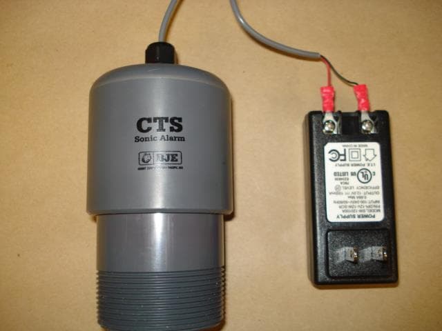
Aug 03, 2014CTS Tank Alarm Sensor
Equipment Class
DXX - Part 15 Low Power Communication Device Transmitter