2AB4F-F10Two Way Radio
Fujian Juston Electronic Equipment Co.,Ltd.
Click to zoom
Application Details
- Equipment Class
- FRF - Part 95 Family Radio Face Held Transmitter
- Date of Grant
- May 26, 2020
- Application Purpose
- Original Equipment
- Date of Application
- May 26, 2020
- Equipment Note
- Two Way Radio
- Frequency Range
- 462.55000000 - 462.72500000
- Country
- China
Documents & Files
Document Text
Text extracted from the exhibit documents filed with the FCC. Open a document above to read the original.
Users Manual
User’s manual Radio Mini Basic Introduction Parts list Radio *1 Li-ion Battery Pack*1 User’s Manual*1 Belt Clip*1 Hand-Strap*1 Adaptor *1 USB cable*1 Basic parameters: Size: 130*52*14 Weight: 80g Operating Voltage:3.3-4.2v DC Channels: 16 Working Temperature: -10°C--+40°C 1. PTT 2 light 3. Mic 4.Speaker 5. Antenna 6. Side key PTT 7.Channel + 8.Channel - 9. Power on /off Switch 10. Volume Switch 11. Microphone Interface 12. Earphone Inte rface 13. USB Interface 14. Battery Status of Indicator light 1- Indicator Green light flashes when radio is receiving. Red light flashes when radio is transmitting. 2-Channel Switch Choosing desired channel to communication from 1-16. When the UP button is pressed, the channel rises.When the DOWN button is pressed, the channel drops and the channel loops. 3-Power Switch Press the power switch key about 2 seconds to turn on the radio. When the radio needs to turn off, press the power switch key about 2 seconds to turn off. 4-PTT The radio has two PTT switches on the side and the front.Press PPT and face to microphone to communicate with the others. Red light flashes. Release PTT to receive and the green light flashes. 5-Monitor F10,F18 Long press channel UP key can turn on the receiving and monitor function for a long time , and then press it to turn off the monitor function. 6-Squelch level The purpose of the squelch is to mute the speaker when no signals are present Lower squelch level ,high background noise hear ,longer communication range ,weaker the anti-inference . Level 0 is to open the squelch . The higher the selected squelch level, the stronger the signals must be when receiving 7-TOT This function can prevent users occupied the present channel for long time and limit TX time, meanwhile prevent radio from damage by long time transmitting If radio continue TX over the limit time, radio will quit TX and sounds a warning sound. To stop warning sound, release the PTT , radio will back to the receiving state. When TX over time, through the bell to carry out early warning in advance 8-Scan When the radio enters 16 channels, it enters the scanning function automatically. 9-Voice Power Please choose the desired language 10-Power Saving Function Please select to active or disable the power save function by PC program software 11-Battery Voltage Alert When the battery voltage is lower than a certain level, the voice will sound "please charge",and prohibit transmitting 12- Busy Channel Lockout If radio programmed with BCLO, pressing PTT to prohibit TX after receiving the signal. 13- Narrow Band (12.5KHz) Radio default setting is narrowband . 14 -Charging Indicator The charger is charged by Android data line. When charging, the indicator light is red. 15-Channel Locking Function Long press the channel DOWN key to hear the “beep” twice, then the channel is locked in the currently set channel. Long press the channel” DOWN” key to unlock the channel after hearing the sound of “di,” and the channel switch can operate normally. Troubleshooting Problem solution No power The battery maybe run out please renew it or recharge it. The battery may not be properly installed.Please take it off and re-install. Battery lasts a short time after charge The battery life is over,please replace new battery Radio continue squeak Radio channel is empty channel, please switch to other channel or write frequency point before use. Warranty Card Contact :__________________________ Company Name___________________________________ ADD:_________________Post Code:_________________________ Tel:__________________Mob.: ____________________________ Fax:_______________ Email: ______________________________ Ordered :______________Model:_____________________________ Ordered No.:___________Purchased Date:_____________________ (S/N): __________________ (EAN):____________________________ Warranty Card No.:_______________________ Trouble Description:________________________ FCC Warning Operation is subject to the following two conditions: (1) This device may not cause interference, and (2) This device must accept any interference, including interference that may cause undesired operation of the device. RF Exposure complianceStatement and operating instructions at the Face up is 0.185W/kg and when properly worn on the body is 0.556 W/kg. This device was tested for typical operations. The device only supports simplex- factor of 50% of the time. For hand-held operation, requirements may not compl be avoided.Use only the supplied or an approved antenna. The device has been tested against the SAR limit (1.6W/kg). The highest SAR value reported under this standard during product certification for use mode and transmitting is no more than the rated duty cycle the radio should be held at least 25mm from the user's face. The use of belt clips, holsters and similar accessories should not contain meatllic components in its assembly. The use of accessories that do not satisfy these y with RF exposure requirements, and should FCC & IC Channel List Channel Frequency Model Channel Frequency Model 1 462.5625 FRS 19 2 462.5875 FRS 20 3 462.6125 FRS 21 4 462.6375 FRS 22 FRS 5 462.6625 FRS FRS 6 462.6875 FRS FRS 7 462.7125 FRS FRS 15 462.6500 16 462.6750 17 462.7000 18 462.7250 462.5500 FRS 462.5750 FRS 462.6000 FRS 462.6250 FRS This EUT is compliance with SAR for controlled exposure limits in IC RSS-102 and had been tested in accordance with the measurement methods and procedures specified in IEEE 1528 and IEC 62209. This equipment should be installed and operated with a minimum distance of 2.5cm must be maintained when held-to-face, and body-worn operations are restricted to the approve doriginal acessories. Cet EUT est conforme aux normes SAR pour les limites d’exposition contrôlée de la norme IC RSS-102 et a été testé conformément aux méthodes et procédures de mesure spécifiées dans les normes IEEE 1528 et IEC 62209. Cet équipement doit être installé et utilisé à une distance minimale de 2,5 cm. être maintenu fac…
Text truncated - open the document above for the full version.
Users Manual
User’s manual Radio Mini Basic Introduction Parts list Radio *1 Li-ion Battery Pack*1 User’s Manual*1 Belt Clip*1 Hand-Strap*1 Adaptor *1 USB cable*1 Basic parameters: Size: 130*52*14 Weight: 80g Operating Voltage:3.3-4.2v DC Channels: 16 Working Temperature: -10°C--+40°C 1. PTT 2 light 3. Mic 4.Speaker 5. Antenna 6. Side key PTT 7.Channel + 8.Channel - 9. Power on /off Switch 10. Volume Switch 11. Microphone Interface 12. Earphone Inte rface 13. USB Interface 14. Battery Status of Indicator light 1- Indicator Green light flashes when radio is receiving. Red light flashes when radio is transmitting. 2-Channel Switch Choosing desired channel to communication from 1-16. When the UP button is pressed, the channel rises.When the DOWN button is pressed, the channel drops and the channel loops. 3-Power Switch Press the power switch key about 2 seconds to turn on the radio. When the radio needs to turn off, press the power switch key about 2 seconds to turn off. 4-PTT The radio has two PTT switches on the side and the front.Press PPT and face to microphone to communicate with the others. Red light flashes. Release PTT to receive and the green light flashes. 5-Monitor F10,F18 Long press channel UP key can turn on the receiving and monitor function for a long time , and then press it to turn off the monitor function. 6-Squelch level The purpose of the squelch is to mute the speaker when no signals are present Lower squelch level ,high background noise hear ,longer communication range ,weaker the anti-inference . Level 0 is to open the squelch . The higher the selected squelch level, the stronger the signals must be when receiving 7-TOT This function can prevent users occupied the present channel for long time and limit TX time, meanwhile prevent radio from damage by long time transmitting If radio continue TX over the limit time, radio will quit TX and sounds a warning sound. To stop warning sound, release the PTT , radio will back to the receiving state. When TX over time, through the bell to carry out early warning in advance 8-Scan When the radio enters 16 channels, it enters the scanning function automatically. 9-Voice Power Please choose the desired language 10-Power Saving Function Please select to active or disable the power save function by PC program software 11-Battery Voltage Alert When the battery voltage is lower than a certain level, the voice will sound "please charge",and prohibit transmitting 12- Busy Channel Lockout If radio programmed with BCLO, pressing PTT to prohibit TX after receiving the signal. 13- Narrow Band (12.5KHz) Radio default setting is narrowband . 14 -Charging Indicator The charger is charged by Android data line. When charging, the indicator light is red. 15-Channel Locking Function Long press the channel DOWN key to hear the “beep” twice, then the channel is locked in the currently set channel. Long press the channel” DOWN” key to unlock the channel after hearing the sound of “di,” and the channel switch can operate normally. Troubleshooting Problem solution No power The battery maybe run out please renew it or recharge it. The battery may not be properly installed.Please take it off and re-install. Battery lasts a short time after charge The battery life is over,please replace new battery Radio continue squeak Radio channel is empty channel, please switch to other channel or write frequency point before use. Warranty Card Contact :__________________________ Company Name___________________________________ ADD:_________________Post Code:_________________________ Tel:__________________Mob.: ____________________________ Fax:_______________ Email: ______________________________ Ordered :______________Model:_____________________________ Ordered No.:___________Purchased Date:_____________________ (S/N): __________________ (EAN):____________________________ Warranty Card No.:_______________________ Trouble Description:________________________ FCC Warning Operation is subject to the following two conditions: (1) This device may not cause interference, and (2) This device must accept any interference, including interference that may cause undesired operation of the device. RF Exposure complianceStatement and operating instructions at the Face up is 0.185W/kg and when properly worn on the body is 0.556 W/kg. This device was tested for typical operations. The device only supports simplex- factor of 50% of the time. For hand-held operation, requirements may not compl be avoided.Use only the supplied or an approved antenna. The device has been tested against the SAR limit (1.6W/kg). The highest SAR value reported under this standard during product certification for use mode and transmitting is no more than the rated duty cycle the radio should be held at least 25mm from the user's face. The use of belt clips, holsters and similar accessories should not contain meatllic components in its assembly. The use of accessories that do not satisfy these y with RF exposure requirements, and should FCC & IC Channel List Channel Frequency Model Channel Frequency Model 1 462.5625 FRS 19 2 462.5875 FRS 20 3 462.6125 FRS 21 4 462.6375 FRS 22 FRS 5 462.6625 FRS FRS 6 462.6875 FRS FRS 7 462.7125 FRS FRS 15 462.6500 16 462.6750 17 462.7000 18 462.7250 462.5500 FRS 462.5750 FRS 462.6000 FRS 462.6250 FRS This EUT is compliance with SAR for controlled exposure limits in IC RSS-102 and had been tested in accordance with the measurement methods and procedures specified in IEEE 1528 and IEC 62209. This equipment should be installed and operated with a minimum distance of 2.5cm must be maintained when held-to-face, and body-worn operations are restricted to the approve doriginal acessories. Cet EUT est conforme aux normes SAR pour les limites d’exposition contrôlée de la norme IC RSS-102 et a été testé conformément aux méthodes et procédures de mesure spécifiées dans les normes IEEE 1528 et IEC 62209. Cet équipement doit être installé et utilisé à une distance minimale de 2,5 cm. être maintenu fac…
Text truncated - open the document above for the full version.
Attestation Statements
Fujian Juston Electronic Equipment Co., Ltd. No.66 Changtai Road,Shudou Industrial Park,Jiangnan Licheng District,Quanzhou, China Apr. 10, 2020 To: Federal Communication Commission Equipment Authorization Branch 7435 Oakland Mills Road Columbia, MD 21046 Subject: Attestation statement regarding the Mobile Radio frequency Applicant: Fujian Juston Electronic Equipment Co., Ltd. No.66 Changtai Road,Shudou Industrial Park,Jiangnan Licheng District,Quanzhou, China TYPE OF QEUIPMENT: Licensed Non-Broadcast Transmitter Held to Face FCC ID: 2AB4F-F10 Dear Sir or Madam I attest that the product has one antenna, one battery capacity, one body-worn and one USB cable. And that the product could program the frequency on computer through interface by manufacturer, is incapable of tuning, or readily being altered, by the end-user. Please contact the undersigned if you have any questions or need any further information. Regards Signature: Name, Job Title and Dept.: Jianghai Wu / General Manager
Attestation Statements
Fujian Juston Electronic Equipment Co., Ltd. No.66 Changtai Road,Shudou Industrial Park,Jiangnan Licheng District,Quanzhou, China Apr. 10, 2020 To: Federal Communication Commission Equipment Authorization Branch 7435 Oakland Mills Road Columbia, MD 21046 Subject: Attestation statement regarding the Mobile Radio frequency Applicant: Fujian Juston Electronic Equipment Co., Ltd. No.66 Changtai Road,Shudou Industrial Park,Jiangnan Licheng District,Quanzhou, China TYPE OF QEUIPMENT: Licensed Non-Broadcast Transmitter Held to Face FCC ID: 2AB4F-F10 Dear Sir or Madam I attest that the product has one antenna, one battery capacity, one body-worn and one USB cable. And that the product could program the frequency on computer through interface by manufacturer, is incapable of tuning, or readily being altered, by the end-user. Please contact the undersigned if you have any questions or need any further information. Regards Signature: Name, Job Title and Dept.: Jianghai Wu / General Manager
Cover Letter(s)
Fujian Juston Electronic Equipment Co.,Ltd. No.66 Changtai Road,Shudou Industrial Park,Jiangnan Licheng District,Quanzhou ,China Apr. 10, 2020 Dear Sir/Madam, We, Fujian Juston Electronic Equipment Co.,Ltd. hereby declare that the software settings have prohibited users from using scrambling functions such as CTCSS and DCS prior to shipment. Sincerely, Name, Job Title and Dept.: Jianghai Wu / General Manager
Cover Letter(s)
Fujian Juston Electronic Equipment Co.,Ltd. No.66 Changtai Road,Shudou Industrial Park,Jiangnan Licheng District,Quanzhou ,China Apr. 10, 2020 Dear Sir/Madam, We, Fujian Juston Electronic Equipment Co.,Ltd. hereby declare that the software settings have prohibited users from using scrambling functions such as CTCSS and DCS prior to shipment. Sincerely, Name, Job Title and Dept.: Jianghai Wu / General Manager
External Photos
External Photos WHOLE VIEW OF EUT TOP VIEW OF EUT BOTTOM VIEW OF EUT FRONT VIEW OF EUT BACK VIEW OF EUT LEFT VIEW OF EUT RIGHT VIEW OF EUT Model: F18 VIEW OF EUT VIEW OF EUT
External Photos
External Photos WHOLE VIEW OF EUT TOP VIEW OF EUT BOTTOM VIEW OF EUT FRONT VIEW OF EUT BACK VIEW OF EUT LEFT VIEW OF EUT RIGHT VIEW OF EUT Model: F18 VIEW OF EUT VIEW OF EUT
ID Label/Location Info
FCC ID and IC Label Location FCC ID: 2AB4F-F10 IC: 21424-F10 HVIN: F10 two way radio HYDX This device complies with Part 15 of the FCC Rules. Operation is subject to the following two conditions: (1) this device may not cause harmful interference, and (2) this device must accept any interference received, including interference that may cause undesired operation. FCC ID: 2AB4F-F10 IC: 21424-F10 HVIN: F18 two way radio HYDX This device complies with Part 15 of the FCC Rules. Operation is subject to the following two conditions: (1) this device may not cause harmful interference, and (2) this device must accept any interference received, including interference that may cause undesired operation.
ID Label/Location Info
FCC ID and IC Label Location FCC ID: 2AB4F-F10 IC: 21424-F10 HVIN: F10 two way radio HYDX This device complies with Part 15 of the FCC Rules. Operation is subject to the following two conditions: (1) this device may not cause harmful interference, and (2) this device must accept any interference received, including interference that may cause undesired operation. FCC ID: 2AB4F-F10 IC: 21424-F10 HVIN: F18 two way radio HYDX This device complies with Part 15 of the FCC Rules. Operation is subject to the following two conditions: (1) this device may not cause harmful interference, and (2) this device must accept any interference received, including interference that may cause undesired operation.
Internal Photos
Internal Photos OPEN VIEW-1 OF EUT OPEN VIEW-2 OF EUT OPEN VIEW-3 OF EUT INTERNAL VIEW-1 OF EUT Antenna INTERNAL VIEW-2 OF EUT INTERNAL VIEW-3 OF EUT INTERNAL VIEW-4 OF EUT INTERNAL VIEW-5 OF EUT INTERNAL VIEW-6 OF EUT INTERNAL VIEW-7 OF EUT INTERNAL VIEW-8 OF EUT Model: F18 VIEW OF EUT OPEN VIEW OF EUT INTERNAL VIEW Antenna INTERNAL VIEW INTERNAL VIEW OF EUT-1 INTERNAL VIEW OF EUT-2 INTERNAL VIEW-3 OF EUT INTERNAL VIEW-4 OF EUT INTERNAL VIEW-5 OF EUT INTERNAL VIEW-6 OF EUT INTERNAL VIEW-7 OF EUT INTERNAL VIEW-8 OF EUT
Internal Photos
Internal Photos OPEN VIEW-1 OF EUT OPEN VIEW-2 OF EUT OPEN VIEW-3 OF EUT INTERNAL VIEW-1 OF EUT Antenna INTERNAL VIEW-2 OF EUT INTERNAL VIEW-3 OF EUT INTERNAL VIEW-4 OF EUT INTERNAL VIEW-5 OF EUT INTERNAL VIEW-6 OF EUT INTERNAL VIEW-7 OF EUT INTERNAL VIEW-8 OF EUT Model: F18 VIEW OF EUT OPEN VIEW OF EUT INTERNAL VIEW Antenna INTERNAL VIEW INTERNAL VIEW OF EUT-1 INTERNAL VIEW OF EUT-2 INTERNAL VIEW-3 OF EUT INTERNAL VIEW-4 OF EUT INTERNAL VIEW-5 OF EUT INTERNAL VIEW-6 OF EUT INTERNAL VIEW-7 OF EUT INTERNAL VIEW-8 OF EUT
RF Exposure Info
Page 1 of 25 CALIBRATION DATA PROBE CALIBRATION DATA Page 2 of 22 Page 3 of 22 Page 4 of 22 Page 5 of 22 Page 6 of 22 Page 7 of 22 Page 8 of 22 Page 9 of 22 Page 10 of 22 Page 11 of 22 DAE CALIBRATION DATA Page 12 of 22 Page 13 of 22 Page 14 of 22 Page 15 of 22 DIPOLE CALIBRATION DATA Page 16 of 22 Page 17 of 22 Page 18 of 22 Page 19 of 22 Page 20 of 22 Page 21 of 22 Page 22 of 22 Page 23 of 22 Page 24 of 22 Page 25 of 22
RF Exposure Info
Page 1 of 41 SAR Test Report Report No.: AGC03393200301FH01 FCC ID : 2AB4F-F10 PRODUCT DESIGNATION : two way radio BRAND NAME : HYDX MODEL NAME : F10; F18 APPLICANT : Fujian Juston Electronic Equipment Co.,Ltd. DATE OF ISSUE : May 13,2020 STANDARD(S) : IEEE Std. 1528:2013 FCC 47 CFR Part 2§2.1093:2013 IEEE C95.1TM:2005 REPORT VERSION : V1.1 Attestation of Global Compliance(Shenzhen) Co., Ltd. CAUTION: This report shall not be reproduced except in full without the written permission of the test laboratory and shall not be quoted out of context. Report No.: AGC03393200301FH01 Page 2 of 41 Report Revise Record Report Version Revise Time Issued Date Valid Version Notes V1.0 / Apr. 10,2020 Invalid Initial Release V1.1 1 st May 13,2020 Valid Updated battery capacity Report No.: AGC03393200301FH01 Page 3 of 41 Test Report Applicant Name Fujian Juston Electronic Equipment Co.,Ltd. Applicant Address No.66 Changtai Road, Shudou Industrial Park, Jiangnan Licheng District, Quanzhou ,China Manufacturer Name Fujian Juston Electronic Equipment Co.,Ltd. Manufacturer Address No.66 Changtai Road, Shudou Industrial Park, Jiangnan Licheng District, Quanzhou ,China Factory Name Fujian Juston Electronic Equipment Co.,Ltd. Factory Address No.66 Changtai Road, Shudou Industrial Park, Jiangnan Licheng District, Quanzhou ,China Product Designation two way radio Brand Name HYDX Model Name F10; F18 Different Description All the same except the model name. EUT Voltage DC3.7 V Applicable Standard IEEE Std. 1528:2013 FCC 47 CFR Part 2§2.1093:2013 IEEE C95.1TM:2005 Test Date Mar. 17,2020 Report Template AGCRT- US -PTT/SAR (2018-02-02) Note: The results of testing in this report apply to the product/system which was tested only. Prepared By Jack Gui (Project Engineer) Mar. 17,2020 Reviewed By Angela Li (Reviewer) May 13,2020 Approved By Forrest Lei (Authorized Officer) May 13,2020 Report No.: AGC03393200301FH01 Page 4 of 41 TABLE OF CONTENTS 1. SUMMARY OF MAXIMUM SAR VALUE ......................................................................................................... 5 2. GENERAL INFORMATION ............................................................................................................................... 6 2.1. EUT DESCRIPTION......................................................................................................................................... 6 3. SAR MEASUREMENT SYSTEM ........................................................................................................................ 7 3.1. THE DASY5 SYSTEM USED FOR PERFORMING COMPLIANCE TESTS CONSISTS OF FOLLOWING ITEMS .................... 7 3.2. DASY5 E-FIELD PROBE ................................................................................................................................. 8 3.3. DATA ACQUISITION ELECTRONICS DESCRIPTION ............................................................................................... 8 3.4. ROBOT .......................................................................................................................................................... 9 3.5. LIGHT BEAM UNIT .......................................................................................................................................... 9 3.6. DEVICE HOLDER .......................................................................................................................................... 10 3.7. MEASUREMENT SERVER ............................................................................................................................... 10 3.8. PHANTOM ................................................................................................................................................. 11 4. SAR MEASUREMENT PROCEDURE ............................................................................................................ 12 4.1. SPECIFIC ABSORPTION RATE (SAR) .............................................................................................................. 12 4.2. SAR MEASUREMENT PROCEDURE ................................................................................................................ 13 5. TISSUE SIMULATING LIQUID ....................................................................................................................... 15 5.1. THE COMPOSITION OF THE TISSUE SIMULATING LIQUID..................................................................................... 15 5.2. TISSUE DIELECTRIC PARAMETERS FOR HEAD AND BODY PHANTOMS ............................................................... 15 5.3. TISSUE CALIBRATION RESULT ....................................................................................................................... 16 6. SAR SYSTEM CHECK PROCEDURE ........................................................................................................... 17 6.1. SAR SYSTEM CHECK PROCEDURES ............................................................................................................. 17 6.2. SAR SYSTEM CHECK ................................................................................................................................... 18 7. EUT TEST POSITION ...................................................................................................................................... 19 7.1. BODY WORN POSITION ................................................................................................................................ 19 8. SAR EXPOSURE LIMITS ............................................................................................................................... 20 9. TEST FACILITY .............................................................................................................................................. 21 10. TEST EQUIPMENT LIST ............................................................................................................................…
Text truncated - open the document above for the full version.
RF Exposure Info
Page 1 of 25 CALIBRATION DATA PROBE CALIBRATION DATA Page 2 of 22 Page 3 of 22 Page 4 of 22 Page 5 of 22 Page 6 of 22 Page 7 of 22 Page 8 of 22 Page 9 of 22 Page 10 of 22 Page 11 of 22 DAE CALIBRATION DATA Page 12 of 22 Page 13 of 22 Page 14 of 22 Page 15 of 22 DIPOLE CALIBRATION DATA Page 16 of 22 Page 17 of 22 Page 18 of 22 Page 19 of 22 Page 20 of 22 Page 21 of 22 Page 22 of 22 Page 23 of 22 Page 24 of 22 Page 25 of 22
RF Exposure Info
Page 1 of 41 SAR Test Report Report No.: AGC03393200301FH01 FCC ID : 2AB4F-F10 PRODUCT DESIGNATION : two way radio BRAND NAME : HYDX MODEL NAME : F10; F18 APPLICANT : Fujian Juston Electronic Equipment Co.,Ltd. DATE OF ISSUE : May 13,2020 STANDARD(S) : IEEE Std. 1528:2013 FCC 47 CFR Part 2§2.1093:2013 IEEE C95.1TM:2005 REPORT VERSION : V1.1 Attestation of Global Compliance(Shenzhen) Co., Ltd. CAUTION: This report shall not be reproduced except in full without the written permission of the test laboratory and shall not be quoted out of context. Report No.: AGC03393200301FH01 Page 2 of 41 Report Revise Record Report Version Revise Time Issued Date Valid Version Notes V1.0 / Apr. 10,2020 Invalid Initial Release V1.1 1 st May 13,2020 Valid Updated battery capacity Report No.: AGC03393200301FH01 Page 3 of 41 Test Report Applicant Name Fujian Juston Electronic Equipment Co.,Ltd. Applicant Address No.66 Changtai Road, Shudou Industrial Park, Jiangnan Licheng District, Quanzhou ,China Manufacturer Name Fujian Juston Electronic Equipment Co.,Ltd. Manufacturer Address No.66 Changtai Road, Shudou Industrial Park, Jiangnan Licheng District, Quanzhou ,China Factory Name Fujian Juston Electronic Equipment Co.,Ltd. Factory Address No.66 Changtai Road, Shudou Industrial Park, Jiangnan Licheng District, Quanzhou ,China Product Designation two way radio Brand Name HYDX Model Name F10; F18 Different Description All the same except the model name. EUT Voltage DC3.7 V Applicable Standard IEEE Std. 1528:2013 FCC 47 CFR Part 2§2.1093:2013 IEEE C95.1TM:2005 Test Date Mar. 17,2020 Report Template AGCRT- US -PTT/SAR (2018-02-02) Note: The results of testing in this report apply to the product/system which was tested only. Prepared By Jack Gui (Project Engineer) Mar. 17,2020 Reviewed By Angela Li (Reviewer) May 13,2020 Approved By Forrest Lei (Authorized Officer) May 13,2020 Report No.: AGC03393200301FH01 Page 4 of 41 TABLE OF CONTENTS 1. SUMMARY OF MAXIMUM SAR VALUE ......................................................................................................... 5 2. GENERAL INFORMATION ............................................................................................................................... 6 2.1. EUT DESCRIPTION......................................................................................................................................... 6 3. SAR MEASUREMENT SYSTEM ........................................................................................................................ 7 3.1. THE DASY5 SYSTEM USED FOR PERFORMING COMPLIANCE TESTS CONSISTS OF FOLLOWING ITEMS .................... 7 3.2. DASY5 E-FIELD PROBE ................................................................................................................................. 8 3.3. DATA ACQUISITION ELECTRONICS DESCRIPTION ............................................................................................... 8 3.4. ROBOT .......................................................................................................................................................... 9 3.5. LIGHT BEAM UNIT .......................................................................................................................................... 9 3.6. DEVICE HOLDER .......................................................................................................................................... 10 3.7. MEASUREMENT SERVER ............................................................................................................................... 10 3.8. PHANTOM ................................................................................................................................................. 11 4. SAR MEASUREMENT PROCEDURE ............................................................................................................ 12 4.1. SPECIFIC ABSORPTION RATE (SAR) .............................................................................................................. 12 4.2. SAR MEASUREMENT PROCEDURE ................................................................................................................ 13 5. TISSUE SIMULATING LIQUID ....................................................................................................................... 15 5.1. THE COMPOSITION OF THE TISSUE SIMULATING LIQUID..................................................................................... 15 5.2. TISSUE DIELECTRIC PARAMETERS FOR HEAD AND BODY PHANTOMS ............................................................... 15 5.3. TISSUE CALIBRATION RESULT ....................................................................................................................... 16 6. SAR SYSTEM CHECK PROCEDURE ........................................................................................................... 17 6.1. SAR SYSTEM CHECK PROCEDURES ............................................................................................................. 17 6.2. SAR SYSTEM CHECK ................................................................................................................................... 18 7. EUT TEST POSITION ...................................................................................................................................... 19 7.1. BODY WORN POSITION ................................................................................................................................ 19 8. SAR EX…
Text truncated - open the document above for the full version.
Contact Information
Applicant
Jianghai Wu
Test Firm
Attestation of Global Compliance (Shenzhen) Co., LDoris Li
[email protected]+86-755-25234088
Technical Specifications
| # | Rule Parts | Frequency Range | Power Output | Emission | Tolerance |
|---|---|---|---|---|---|
| 2 | 95B | 462.55 MHz - 462.725 MHz | 2 W | 11K0F3E | 2.5 ppm |
Other Applications from Fujian Juston Electronic Equipment Co.,Ltd.

2AB4FD1000
Jul 11, 2022DMR Digital Mobile Radio
Equipment Class
CSR - Scanning Receiver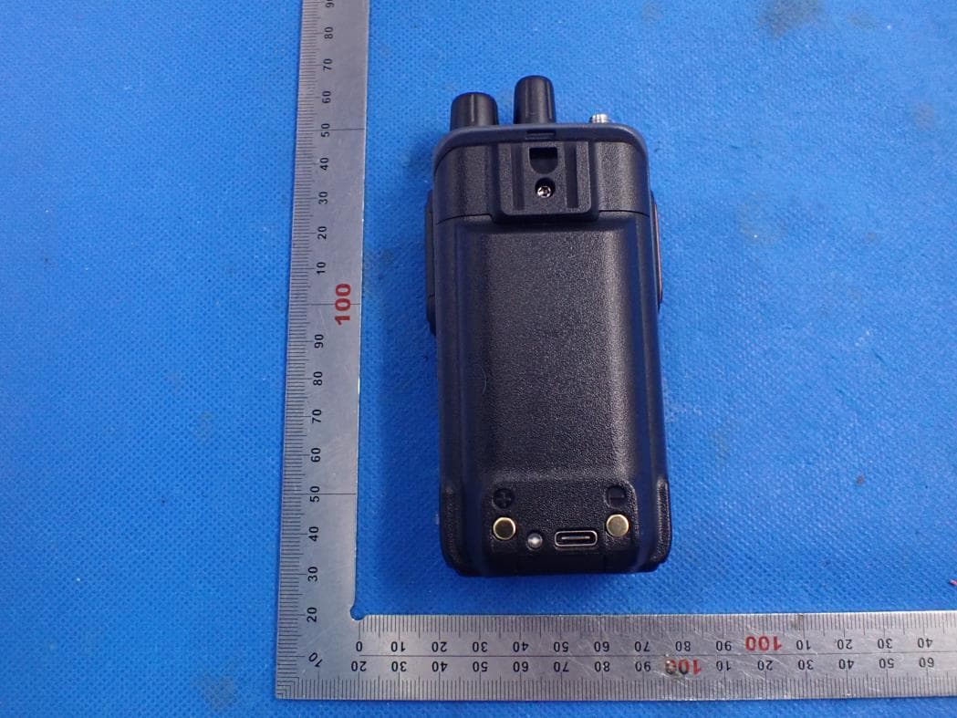
2AB4FMURS
Apr 25, 2021Two way radio
Equipment Class
CSR - Scanning Receiver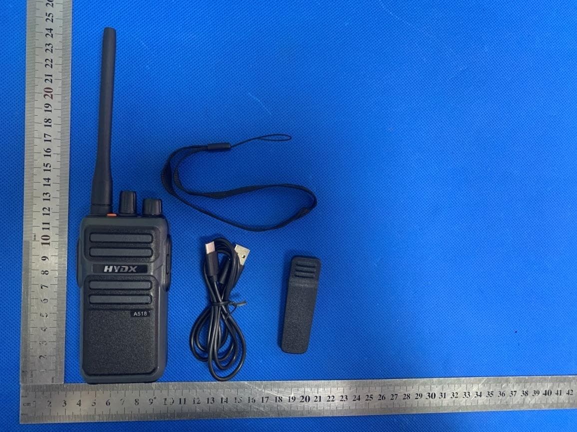
2AB4FA518
Apr 20, 2020Two Way Radio
Equipment Class
FRF - Part 95 Family Radio Face Held Transmitter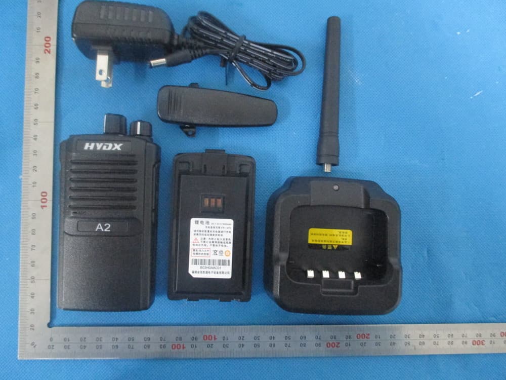
2AB4FA2V
Apr 29, 2014Handheld Two Way Radio
Equipment Class
TNF - Licensed Non-Broadcast Transmitter Held to Face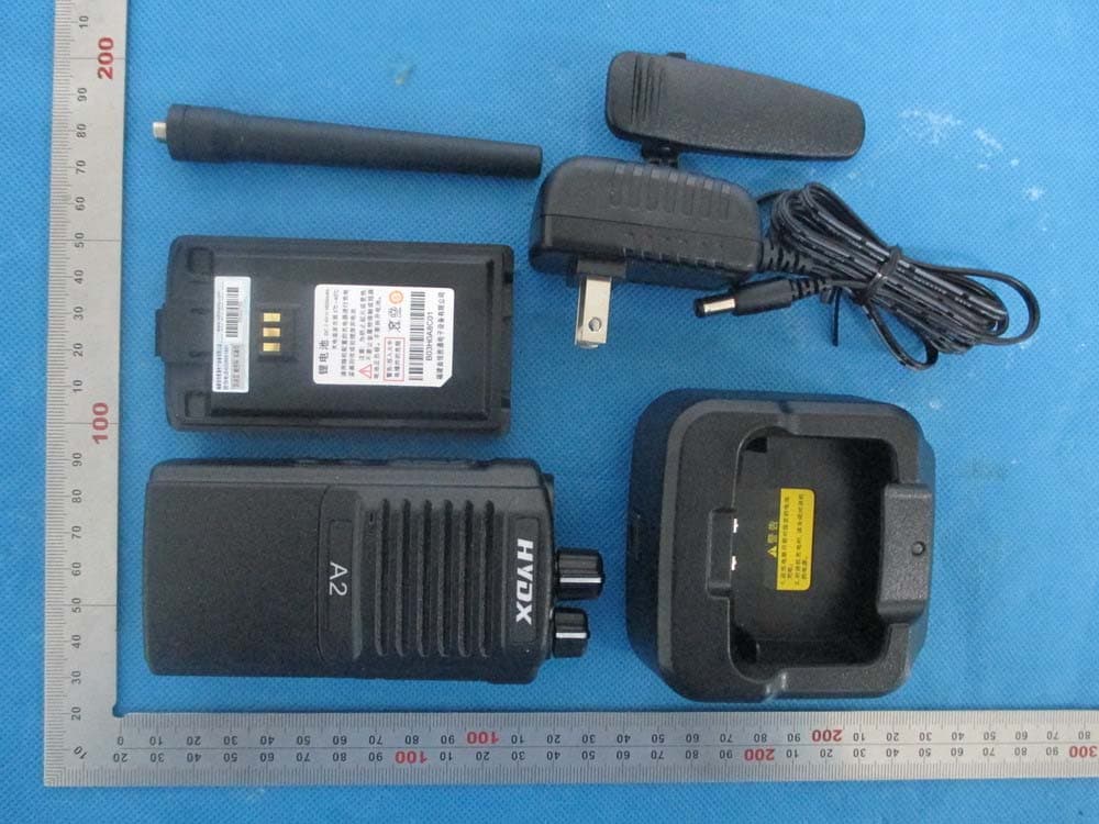
2AB4FA2U
Apr 09, 2014Handheld Two Way Radio
Equipment Class
TNF - Licensed Non-Broadcast Transmitter Held to Face