2AB4LCPK22013DS CHAT-PAK
Cane Wireless Inc.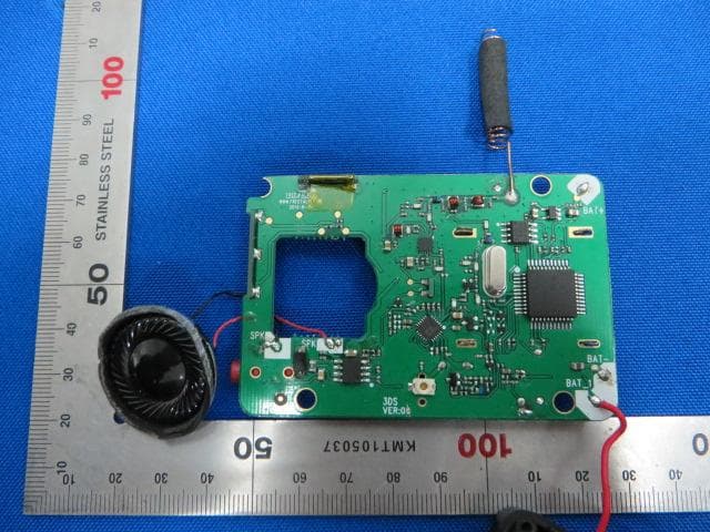
Click to zoom
Application Details
- Equipment Class
- FRF - Part 95 Family Radio Face Held Transmitter
- Date of Grant
- Apr 09, 2014
- Application Purpose
- Original Equipment
- Date of Application
- Apr 09, 2014
- Equipment Note
- 3DS CHAT-PAK
- Frequency Range
- 462.55000000 - 462.72500000
- Company
- Cane Wireless Inc.
- Country
- United States
Documents & Files
Document Text
Text extracted from the exhibit documents filed with the FCC. Open a document above to read the original.
Users Manual
Owner’s Manual Thanks for choosing communication accessory for your Portable Video Game System! Please read this instruction manual completely before attempting to install and operate the unit. Features ○ Impact Resistant ABS plastic protective case ○ One to One, One to Many Communication Function ○ 22 Channels (14 FRS & 8 GMRS Frequencies) ○ 38 CTCSS sub codes ○ Up to 4 Mile Range* ○ 10 Selectable Call Tone Alerts ○ Auto Squelch ○ Auto Battery Saving Mode ○ VOX for easy Hands-Free Operation ○ Channel Scan ○ Voice Scramble for added privacy ○ Roger Beep ○ Auto Power Off (APO) ○ Keypad Lock ○ Backlit LCD Display ○ Low Battery indication and Low-battery alarm function ○ Accessory Jack for Optional Headset Accessory *Range stated is optimal based on line of sight with no obstructions and game unit turned off. Actual range may vary and will depend on environment and/or use conditions. Product Safety and RF Exposure This device complies with part 15 of the FCC Rules. Operation is subject to the following two conditions: 1.This device may not cause harmful interference. 2.This device must accept any interference received, including interference that may cause undesired operation. FCC Radiation Exposure: This equipment complies with FCC radiation exposure limits set forth for uncontrolled environment. This device and its antenna must not be co-located or operating in conjunction with any other antenna or transmitter. Your wireless hand-held portable transceiver contains a low power transmitter. When transmitting, it sends out radio frequency (RF) signals. This device is authorized to operate at a duty factor not to exceed 50%. Important Note: To maintain good communication quality, hold the radio with the microphone at least 3 inches from your mouth and speak in a normal voice. Ensure the radio and antenna is at least one inch (2.5cm) from your body when transmitting. Any changes or modifications not expressly approved by the manufacturer could void the user’s authority to operate this equipment. Any adjustment to your radio must be made by qualified technicians. Your device may interfere with TVs or radios, even when operating properly. To determine whether your communicator is causing interference, simply turn it off. If the interference ends, your device is causing it. Try to eliminate interference by moving your communicator away from the receiver. If you cannot eliminate interference completely, please stop using this device. Hazardous Environments: Do not operate the communicator in hazardous environments, explosion or fire may result. Do not operate the communicator near unshielded electrical blasting caps. Under certain conditions, radios can interfere with blasting operations and may cause an explosion. Turn your radio to the OFF position to prevent accidental transmission when in a blasting area or in areas posted: “Turn off two-way radios.” Construction crews often use remote control RF devices to set off explosives. Never use cleaners or solvents to clean your device. Use a dry, lint-free cloth to clean the battery contacts. Do not submerge the unit in water. LCD Screen 1. Segment Display 2. Channel Indicator 3. Battery Level Meter 4. CTCSS code Indicator 5. Volume Level Indicator 6. Receive Indicator 7. Transmit Indicator 8. Scan Indicator 9. Call tone Indicator 10. Keypad Lock Indicator 11. VOX Indicator Buttons and Controls To Install and Replace the Battery Your Chat-Pak radio uses 3 AAA alkaline batteries or the optional NiMH rechargeable battery pack (sold separately). To install the batteries 1. Make sure your radio is turned OFF. 2. Remove the battery compartment door by inserting a coin or flat head screwdriver into the slot on the battery door and pry away from the radio, allowing the battery door to be removed. 3. Install the battery into the battery compartment. Be certain to follow the + and – symbols in the compartment. Installing the batteries incorrectly will prevent the unit from operating. 4. Replace the battery compartment door. When the battery in the unit is low, the low battery level icon will appear on the display and the unit will emit an audible alert. Replace the batteries immediately. If you use the rechargeable NiMH battery pack, the radio can be charged directly using the supplied A/C charging adapter. Make sure to turn the radio OFF before charging. 1. Insert the NiMH battery pack into the battery compartment. 2. Connect the A/C Adapter Charger into an A/C Wall outlet. 3. Insert the A/C Adapter Charger plug into the Headset/Charger Jack located on the side of your unit (be careful NOT to plug into the audio jack of your game device). The low battery icon will appear on the display while charging and disappear when fully charged. Charge the battery pack for 16 hours before initial use. Charging the battery Installing Your Game Device 1. Open the Top Cover on your Chat-Pak communication device. 2. Insert the lid of your game device into the Top Cover of the Chat-Pak. 3. Snap the Bottom Cover of the Chat-Pak onto the base of your game device. Turning ON and Adjusting Volume 1. Press and hold the MENU/ key for to turn the radio ON. 2. Increase the volume by pressing the UP key. To decrease the volume, press the Down key. 3. Press and hold the MENU/ key again to turn the radio OFF. Navigating Through the Menu 1. In Standby mode, enter Menu mode by short press of the Menu key. A key-beep tone will sound confirming the radio is in Menu mode. 2. The unit automatically times out of Menu mode and enters Standby mode in 8 seconds if no button is pressed. 3. Press PTT/Call key at anytime to exit Menu mode and return to Standby mode. Menu u Channel Code VOX (OFF,1,2,3) Scramble ON/OFF APO ON/OFF Call Tone Choosing Channel and Code This device has multiple Channels and CTCSS codes to choose from for communicating with others: 1. In Standby Mode, press the menu key briefly to enter Menu mode. A key beep tone is locally generated and the Channel number on the LCD Displ…
Text truncated - open the document above for the full version.
ID Label/Location Info
Label Label Location Cane Wireless Inc. M/N: CPK2201 Made in china FCC ID: 2AB4LCPK2201
Internal Photos
1 of 3 Internal Photo (1) EUT Photo (2) EUT Photo (3) EUT Photo (4) EUT Photo (5) EUT Photo (6) EUT Photo
RF Exposure Info
MRT Technology (Suzhou) Co., Ltd Report No.: 1403RSU02202 Phone: +86-512-66308358 Report Version: V02 Fax: +86-512-66308368 Issue Date: 04-10-2014 Web: www.mrt-cert.com FCC ID: 2AB4LCPK2201 Page Number: 1 of 5 RF Exposure Evaluation Declaration FCC ID: 2AB4LCPK2201 APPLICANT: Cane Wireless Inc. Application Type: Certification Product: 3DS CHAT-PAK Model No.: CPK2201 Test Date: March 16 ~ 28, 2014 Reviewed By : ( Robin Wu ) Approved By : ( Marlin Chen ) The test results relate only to the samples tested. The test results shown in the test report are traceable to the national/international standards through the calibration of the equipment and evaluated measurement uncertainty herein. The test report shall not be reproduced except in full without the written approval of MRT Technology (Suzhou) Co., Ltd. Report No.: 1403RSU02202 FCC ID: 2AB4LCPK2201 Page Number: 2 of 5 Revision History Report No. Version Description Issue Date 1403RSU02202 Rev. 01 Initial report 03-28-2014 1403RSU02202 Rev. 02 Modify the MPE calculation 04-10-2014 Report No.: 1403RSU02202 FCC ID: 2AB4LCPK2201 Page Number: 3 of 5 1. RF Exposure Evaluation 1.1. Limits SAR Test Exclusion Thresholds for 100 MHz – 6 GHz and ≤ 50 mm Approximate SAR Test Exclusion Power Thresholds at Selected Frequencies and Test Separation Distances are illustrated in the following Table. The equation and threshold in Note 1 must be applied to determine SAR test exclusion. MHz 5 10 15 20 25 mm 150 39 77 116 155 194 SAR Test Exclusion Threshold (mW) 300 27 55 82 110 137 450 22 45 67 89 112 835 16 33 49 66 82 900 16 32 47 63 79 1500 12 24 37 49 61 1900 11 22 33 44 54 2450 10 19 29 38 48 3600 8 16 24 32 40 5200 7 13 20 26 33 5400 6 13 19 26 32 5800 6 12 19 25 31 MHz 30 35 40 45 50 mm 150 232 271 310 349 387 SAR Test Exclusion Threshold (mW) 300 164 192 219 246 274 450 134 157 179 201 224 835 98 115 131 148 164 900 95 111 126 142 158 1500 73 86 98 110 122 1900 65 76 87 98 109 2450 57 67 77 86 96 3600 47 55 63 71 79 5200 39 46 53 59 66 5400 39 45 52 58 65 5800 37 44 50 56 62 Note 1: The 1-g and 10-g SAR test exclusion thresholds for 100 MHz to 6 GHz at test separation Report No.: 1403RSU02202 FCC ID: 2AB4LCPK2201 Page Number: 4 of 5 distances ≤ 50 mm are determined by: [(max. power of channel, including tune-up tolerance, mW)/(min. test separation distance, mm)] * [√f(GHz)] ≤ 3.0 for 1-g SAR and ≤ 7.5 for 10-g extremity SAR, where f(GHz) is the RF channel transmit frequency in GHz Power and distance are rounded to the nearest mW and mm before calculation The result is rounded to one decimal place for comparison 3.0 and 7.5 are referred to as the numeric thresholds in the step 2 below The test exclusions are applicable only when the minimum test separation distance is ≤ 50 mm and for transmission frequencies between 100 MHz and 6 GHz. When the minimum test separation distance is < 5 mm, a distance of 5 mm according to 5) in section 4.1 is applied to determine SAR test exclusion. 1.2. Test Procedure The operating configurations of handheld PTT two-way radios generally require SAR testing for in-front-of the face and body-worn accessory exposure conditions. A duty factor of 50% should be applied to determine compliance for radios with maximum operating duty factors ≤ 50 %. For PTT radios operating in the 100 MHz to 1 GHz range, according to general population exposure requirements, SAR test exclusion may be applied for in-front-of the face and body-worn accessory exposure conditions according to the SAR Test Exclusion Threshold conditions and duty factor compensated maximum conducted output power. When a body-worn accessory is not supplied with the PTT radio, a test separation distance ≤ 10 mm must be applied to determine body-worn accessory SAR test exclusion. A test separation distance of 25 mm must be applied for in-front-of the face SAR test exclusion and SAR measurements. Report No.: 1403RSU02202 FCC ID: 2AB4LCPK2201 Page Number: 5 of 5 1.3. Test Result of RF Exposure Evaluation The two-way radio device is intended for use in the Held to face exposure condition and the general population RF exposure environment, and always keep the antenna at least 2.5 cm (1 inch) away from the body The device is intended for use in the Held to face condition and the general population RF exposure environment, and always keep the antenna at least 2.5 cm (1 inch) away from the body. Per FCC KDB 447498 D01v05r02, the SAR exclusion threshold for distances <50mm is defined by the following equation: The measured maximum effective radiated power was 91.6(mW). From these data, the radiated power with 50 % duty cycle is: The radiated power = 91.6(mW)*50% = 45.8(mW) [(45.8mW/25)* √0.4675625] = 1.253 < 3.0. From the above calculation, it is concluded that the device can be exempt from SAR test. The End
Test Report
MRT Technology (Suzhou) Co., Ltd Report No.: 1403RSU02201 Phone: +86-512-66308358 Report Version: Rev. 02 Fax: +86-512-66308368 Issue Date: 04-10-2014 Web: www.mrt-cert.com FCC ID: 2AB4LCPK2201 Page Number: 1 of 32 FCC ID: 2AB4LCPK2201 APPLICANT: Cane Wireless Inc. Application Type: Certification Product: 3DS CHAT-PAK Model No.: CPK2201 FCC Rule Part(s): FCC Part 95: 2013 Test Procedure(s): ANSI/TIA-603-D: 2010 Test Date: March 16 ~ 28, 2014 MEASUREMENT REPORT FCC PART 95 Reviewed By : ( Robin Wu ) Approved By : ( Marlin Chen ) The test results relate only to the samples tested. This equipment has been shown to be capable of compliance with the applicable technical standards as indicated in the measurement report and was tested in accordance with the measurement procedures specified in ANSI/TIA-603-D: 2010. Test results reported herein relate only to the item(s) tested. The test report shall not be reproduced except in full without the written approval of MRT Technology (Suzhou) Co., Ltd. Report No.: 1403RSU02201 FCC ID: 2AB4LCPK2201 Page Number: 2 of 32 Revision History Report No. Version Description Issue Date 1403RSU02201 Rev. 01 Initial report 2014-03-28 1403RSU02201 Rev. 02 Check the OBW data 2014-04-10 Report No.: 1403RSU02201 FCC ID: 2AB4LCPK2201 Page Number: 3 of 32 CONTENTS Description Page §2.1033 General Information ......................................................................................................... 5 1. INTRODUCTION ..................................................................................................................... 6 1.1. Scope ........................................................................................................................... 6 1.2. MRT Test Location ....................................................................................................... 6 2. PRODUCT INFORMATION ..................................................................................................... 7 2.1. Equipment Description .................................................................................................. 7 2.2. Frequency / Channel Opreation .................................................................................... 7 2.3. Test Standards ............................................................................................................. 8 2.4. Test Methodology ......................................................................................................... 8 3. TEST EQUIPMENT CALIBRATION DATA .............................................................................. 9 4. MEASUREMENT UNCERTAINTY .......................................................................................... 11 5. TEST RESULT ...................................................................................................................... 12 5.1. Summary .................................................................................................................... 12 5.2. RF Output Power ........................................................................................................ 13 5.2.1. Provisions Applicable .............................................................................................. 13 5.2.2. Test Procedure........................................................................................................ 13 5.2.3. Test Setup ............................................................................................................... 14 5.2.4. Test Result .............................................................................................................. 15 5.3. Modulation Characteristics .......................................................................................... 16 5.3.1. Provisions Applicable .............................................................................................. 16 5.3.2. Test Procedure........................................................................................................ 16 5.3.2.1 Frequency deviation ............................................................................................... 16 5.3.2.2 Modulation Frequency Response ........................................................................... 16 5.3.2.3 Audio Low Pass Filter Response ............................................................................ 17 5.3.3. Test Setup ............................................................................................................... 17 5.3.4. Test Result .............................................................................................................. 18 5.4. Occupied Bandwidth And Emission Mask ................................................................... 22 5.4.1. Provisions Applicable .............................................................................................. 22 5.4.2. Test Procedure........................................................................................................ 22 5.4.3. Test Setup ............................................................................................................... 22 5.4.4. Test Result .............................................................................................................. 23 5.5. Unwanted Radiated Spurious Emission ...................................................................... 25 5.5.1. Provisions Applicable .............................................................................................. 25 5.5.2. Test Procedure........................................................................................................ 25 Report No.: 1403RSU02201 FCC ID: 2AB4LCPK2201 Page Number: 4 of 32 5.5.3. Test Setup ............................................................................................................... 26 5.5.4. Test Result. ...........................................................................................................…
Text truncated - open the document above for the full version.
Test Setup Photos
1 of 2 Test Setup Photo Description: Radiated Emission Test Setup for 9kHz ~ 30MHz Description: Radiated Emission Test Setup for 30MHz ~ 1GHz Description: Radiated Emission Test Setup for 1GHz ~ 18GHz Description: Radiated Emission Test Setup for 18GHz ~ 40GHz
Contact Information
Applicant
Jianqiang Yang(Manager)
Test Firm
MRT Technology (Suzhou) Co., LtdWu Jian
[email protected]86-512-66308358
Technical Specifications
| # | Rule Parts | Frequency Range | Power Output | Emission | Tolerance |
|---|---|---|---|---|---|
| 3 | 95A | 462.55 MHz - 462.725 MHz | 85.00 mW | 7K63F3E | 0.0000193 % |