2AB5TMINIBOOMBluetooth Speaker
Shenzhen MeiDong Acoustics Co., LTD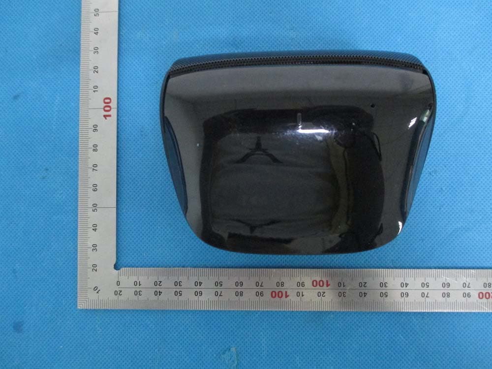
Click to zoom
Application Details
- Equipment Class
- DTS - Digital Transmission System
- Date of Grant
- Jun 26, 2014
- Application Purpose
- Original Equipment
- Date of Application
- Jun 26, 2014
- Equipment Note
- Bluetooth Speaker
- Frequency Range
- 2402.00000000 - 2480.00000000
- Country
- China
Documents & Files
Document Text
Text extracted from the exhibit documents filed with the FCC. Open a document above to read the original.
Users Manual
User’s Guide Bluetooth Speaker Model name:Miniboom Brand name:cowin FCC ID:2AB5TMINIBOOM 1. Introduction 2. Battery Precaution 3. Getting Started 4. Cable Connection 5. Bluetooth Connection 6. NFC Connection 7. Microphone Usage 8. LED Display Status 9. Battery Charging 10. Product Care Please read the following safety warning and precaution before using your device. Contents -1- 50mAh -2- 1. Introduction easily connected with your audio source or video devices during your traveling and daily use. It supports both Bluetooth and line-in usage. Specification Rechargeable battery with charging option from USB cable Operating range up to 0 meters Battery Capacity: 14 1 Thank you for purchasing the Miniboom system. This device can be 2. Battery Precaution The device can be powered by a built-in rechargeable lithium battery. Please charge the battery for at least 8 hours before your first use of device. If the device is not used for a long period of time, the battery may be out of power. Please charge the battery. Rechargeable batteries are only to be charged under adult supervision. Use only the supplied USB micro cable to recharge the battery. Improper charging may damage the battery and the device. Do not attempt to open the rechargeable battery or battery pack. There is not serviceable part inside. Should a battery leak, the device may become damaged. Clean the battery compartment immediately, avoiding to touch your skin. Keep the battery out of reach of children. If swallowed, consult a physician immediately. Avoid storing the battery in extremely hot or cold environment. A device with a hot or cold battery may not work temporarily, even when the battery is fully charged. Do not dispose batteries in a fire as they may explode. Batteries may also explode if damaged. Please dispose them according to local regulation. Do not dispose them as household waste. -3- 3. Getting Started -4- 4 . Cable Connection Audio input cable Aux Previous Volume down Volume up Bluetooth pairing key Next Play/Pause/Answer/end calls ON/OFF AUX Micro USB ON OFF Microphone 5. Bluetooth Connection -5- Pairing Miniboom to your smartphone (smartphone should be away from your speaker within 10 meters) 1.Activate pairing mode on Miniboom by switching “ON/OFF” button to“ON”. The LED will flash in green color. 2. On your smartphone navigate to the Bluetooth function (refer to the smartphone owner’s manual to locate Bluetooth function). 3. Select “Set Up” Bluetooth or turn “ON” Bluetooth. 4. Select “Search” or “Discover” devices. 5. Select “Bluetooth”. 6. If requested, type the password 0000 7. Press the Enter key. After completing the steps above, a message on your smart phone will appear to confirming that your device is now paired/connected. In case of unsuccessful pairing, Push to “OFF” and restart it to “ON”. 1. If you turn off the device, but the Bluetooth on your smartphone remains open, when you restart the device, the Bluetooth will be connected automatically. 2. When your smartphone and this speaker are apart beyond bluetooth receiving range, after 10 minutes, this speaker will disconnect with your smartphone and turn into pairing mode. If within 10 minutes your smartphone is back, will connect with this speaker automatically. 3. If long press “ ” button, the speaker will be disconnected and ready to pair with other smartphone. 6. NFC Connection NFC: Near Field Communication, is a set of standard for Smartphone and this speaker to establish Bluetooth radio communication with each other by touching them together or bringing them into close proximity, usually no more than a few centimeters. -6- 7. Microphone usage Please activate the NFC function (subjects to tablets own setting) of your bluetooth device. Bring your bluetooth device close to speaker, as above picture. Your bluetooth device will ask you whether you need to pair thespeaker, confirm by “Yes” or “OK”, then the pairing process iscompleted. When a phone call comes in, you could talk through the microphone on speaker. Long press pause button, you could call the last number you called on your call records. Note:The NFC tag is passive. 9. Battery Charging The device has a built-in rechargeable lithium battery that can be charged by connecting to the USB port of your computer or into an AC adapter which contains a USB port. When charging is completed, the red light will go off. -7- 8. LED Display Status Flash quickly Stay solid No light Flash quickly Stay solid LED Display It’s ready to pair It's paired Power off/ Full charged Low battery Charging Light indication Green Light Red Light 10. Product care Your device is designed to be light, compact and durable. As an electronic device, must be treated carefully. Putting unnecessary pressure on it or striking the device against other objects may cause damage. it -8- Do not drop, crush, bend or apply excessive force to the device. Do not expose your device to moisture, extreme or prolonged heat, cold, humidity, or other adverse conditions. Avoid storing it in damp, humid or wet places. It is not waterproof. Clean the unit with a soft cloth or damp chamois leather. Never use solvents. The Unit can only be opened by qualified person. This device contains magnets. Keep magnetic field sensitive products such as credit cards and video screen away from this device to avoid damage or malfunction. This device complies with part 15 of the FCC rules. Operation is subject to the following two conditions: (1) this device may not cause harmful interference, and (2) this device must accept any interference received, including interference that may cause undesired operation. Changes or modifications to this unit not expressly approved by the party responsible for compliance could void the user’s authority to operate the equipment.
Cover Letter(s)
May 26, 2014 Federal Communication Commission Authorization and Evaluation Division FCC ID: 2AB5TMINIBOOM Re: Confidentiality Request Pursuant to Sections 0.457 and 0.459 of the Commission’s Rules, the applicant hereby requests confidential treatment of information applied this application as outlined below: 1: Block Diagram 2: Circuit Diagram 3: Parts List 4.Operational Description The above materials contain trade secrets and proprietary information not customarily released to the public. The public disclosure of these matters might be harmful to the applicant and provide unjustified benefits to its competitors. The Applicant understands that pursuant to Rules 0.457, disclosure of this Application and all accompanying documentation will not be made before the date of the Grant for this application. Sincerely, Shenzhen MeiDong Acoustics Co., LTD Contact person: Yu KaI Title: Manager
External Photos
External Photos Model:Miniboom TOP VIEW OF EUT BOTTOM VIEW OF EUT FRONT VIEW OF EUT BACK VIEW OF EUT LEFT VIEW OF EUT RIGHT VIEW OF EUT Model:MiniboomII TOP VIEW OF EUT BOTTOM VIEW OF EUT FRONT VIEW OF EUT BACK VIEW OF EUT LEFT VIEW OF EUT RIGHT VIEW OF EUT
ID Label/Location Info
FCC ID Label Location Model: Miniboom Brand Name: cowin FCC ID: 2AB5TMINIBOOM MiniboomII
Internal Photos
Internal Photos OPEN VIEW OF EUT-1 OPEN VIEW OF EUT-2 NFC tag INTERNAL VIEW OF EUT-1 INTERNAL VIEW OF EUT-2 INTERNAL VIEW OF EUT-3 INTERNAL VIEW OF EUT-4 BT Antenna
Test Report
Report No.: AGC00014140502FE08 Page 1 of 54 FCC Test Report Report No.: AGC00014140502FE08 FCC ID : 2AB5TMINIBOOM APPLICATION PURPOSE : Original Equipment PRODUCT DESIGNATION : Bluetooth Speaker BRAND NAME : cowin MODEL NAME : Miniboom, MiniboomII CLIENT : Shenzhen MeiDong Acoustics Co., LTD DATE OF ISSUE : May 22, 2014 STANDARD(S) : FCC Part 15 Rules REPORT VERSION : V1.0 Attestation of Global Compliance (Shenzhen) Co., Ltd CAUTION: This report shall not be reproduced except in full without the written permission of the test laboratory and shall not be quoted out of context. Report No.: AGC00014140502FE08 Page 2 of 54 Report Revise Record Report Version Revise Time Issued Date Valid VersionNotes V1.0 / May 22, 2014 Valid Original Report Report No.: AGC00014140502FE08 Page 3 of 54 TABLE OF CONTENTS 1. VERIFICATION OF COMPLIANCE......................................................................................................... 5 2.GENERAL INFORMATION ...................................................................................................................... 6 2.1PRODUCT DESCRIPTION ............................................................................................................... 6 2.2 RELATED SUBMITTAL(S)/GRANT(S) ............................................................................................. 6 2.3TEST METHODOLOGY .................................................................................................................... 6 2.4 TEST FACILITY ................................................................................................................................ 6 2.5 SPECIAL ACCESSORIES ................................................................................................................ 6 2.6 EQUIPMENT MODIFICATIONS ....................................................................................................... 7 2.7 MEASUREMENT UNCERTAINTY ................................................................................................... 7 3. SYSTEM TEST CONFIGURATION ......................................................................................................... 8 3.1 CONFIGURATION OF TESTED SYSTEM ....................................................................................... 8 3.2 EQUIPMENT USED IN TESTED SYSTEM ...................................................................................... 8 4. SUMMARY OF TEST RESULTS ............................................................................................................. 9 5. DESCRIPTION OF TEST MODES .......................................................................................................... 9 6. ANTENNA REQUIREMENT .................................................................................................................. 10 6.1. STANDARD APPLICABLE ............................................................................................................ 10 6.2. TEST RESULT .............................................................................................................................. 10 7. RADIATED EMISSION .......................................................................................................................... 11 7.1 MEASUREMENT PROCEDURE .................................................................................................... 11 7.2 TEST SETUP .................................................................................................................................. 12 7.3 TEST EQUIPMENT ........................................................................................................................ 13 7.4 LIMITS AND MEASUREMENT RESULT ........................................................................................ 13 7.5 TEST RESULT ............................................................................................................................... 13 8. BAND EDGE EMISSION ....................................................................................................................... 26 8.1. MEASUREMENT PROCEDURE ................................................................................................... 26 8.2. TEST SET-UP ............................................................................................................................... 26 8.3. TEST RESULT .............................................................................................................................. 27 9. 6DB BANDWIDTH ................................................................................................................................ 31 9.1. TEST EQUIPMENT LIST AND DETAILS ....................................................................................... 31 9.2. TEST PROCEDURE ...................................................................................................................... 31 9.3. SUMMARY OF TEST RESULTS/PLOTS ...................................................................................... 31 10. CONDUCTED OUTPUT POWER ....................................................................................................... 34 10.1. MEASUREMENT PROCEDURE ................................................................................................. 34 10.2. TEST SET-UP (BLOCK DIAGRAM OF CONFIGURATION) ........................................................ 34 10.3. LIMITS AND MEASUREMENT RESULT ..................................................................................... 35 11. MAXIMUM CONDUCTED OUTPUT POWER SPECTRAL DENSITY ................................................ 37 Report No.: AGC00014140502FE08 Page 4 of 54 11.1 MEASUREMENT PROCEDURE .................................................................................................. 37 11.2 TEST SET-UP (BLOCK DIAGRAM OF CONFIGURATION) ......................................................... 37 11.3 MEASUREMENT EQU…
Text truncated - open the document above for the full version.
Test Setup Photos
APPENDIX IV PHOTOGRAPHS OF TEST SETUP FCC LINE CONDUCTED EMISSION TEST SETUP FCC RADIATED EMISSION TEST SETUP
Contact Information
Applicant
Huang ping hua
Test Firm
Attestation of Global Compliance Shenzhen Co. Ltd.Forrest Lei
Technical Specifications
| # | Rule Parts | Frequency Range | Power Output |
|---|---|---|---|
| 1 | 15C | 2.40 GHz - 2.48 GHz | 800.00 µW |
Other Applications from Shenzhen MeiDong Acoustics Co., LTD
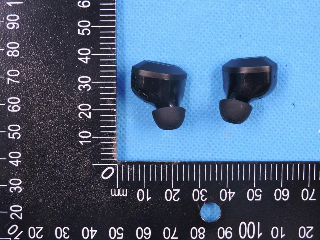
2AB5T-APEX
Jan 04, 2021TWS BLUETOOTH EARBUDS
Equipment Class
DSS - Part 15 Spread Spectrum Transmitter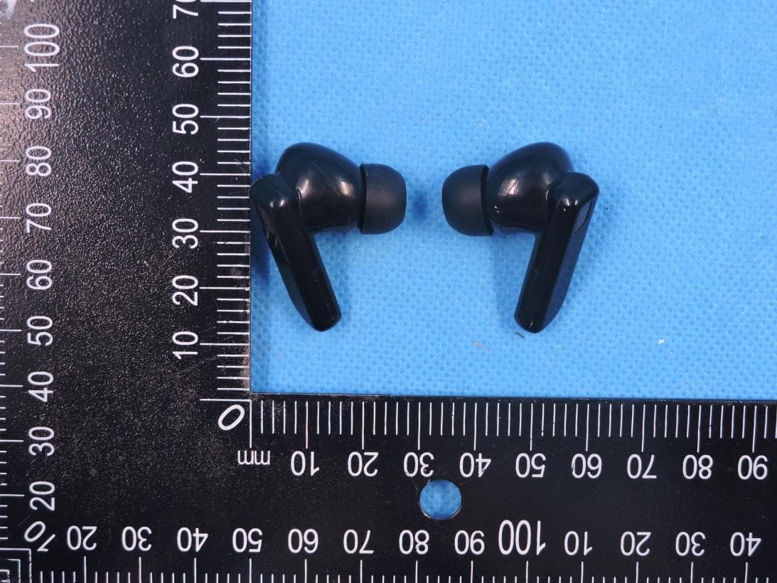
2AB5T-APEXPRO
Jan 04, 2021TWS BLUETOOTH EARBUDS
Equipment Class
DSS - Part 15 Spread Spectrum Transmitter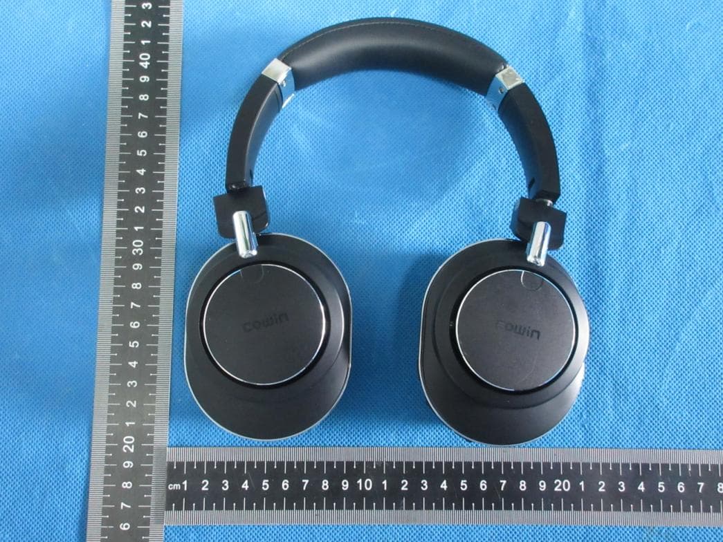
2AB5T-SE9
Nov 18, 2020ANC Wireless headphones
Equipment Class
DTS - Digital Transmission System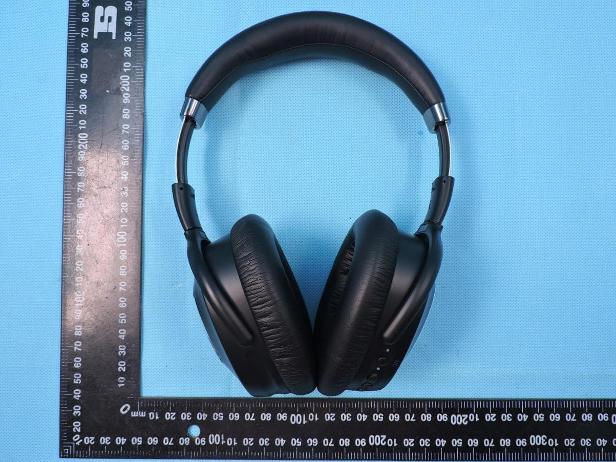
2AB5T-SE8
May 24, 2020Active noise canceling bluetooth headset
Equipment Class
DSS - Part 15 Spread Spectrum Transmitter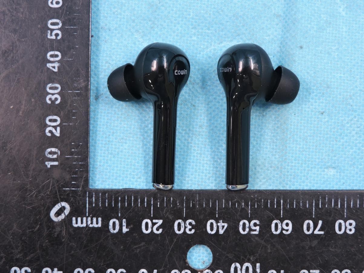
2AB5T-KY03
Jan 14, 2020TWS BLUETOOTH ADPHONE
Equipment Class
DSS - Part 15 Spread Spectrum Transmitter