2AB65COBRA100RXCR2SCobra 100
Schmidiger GmbH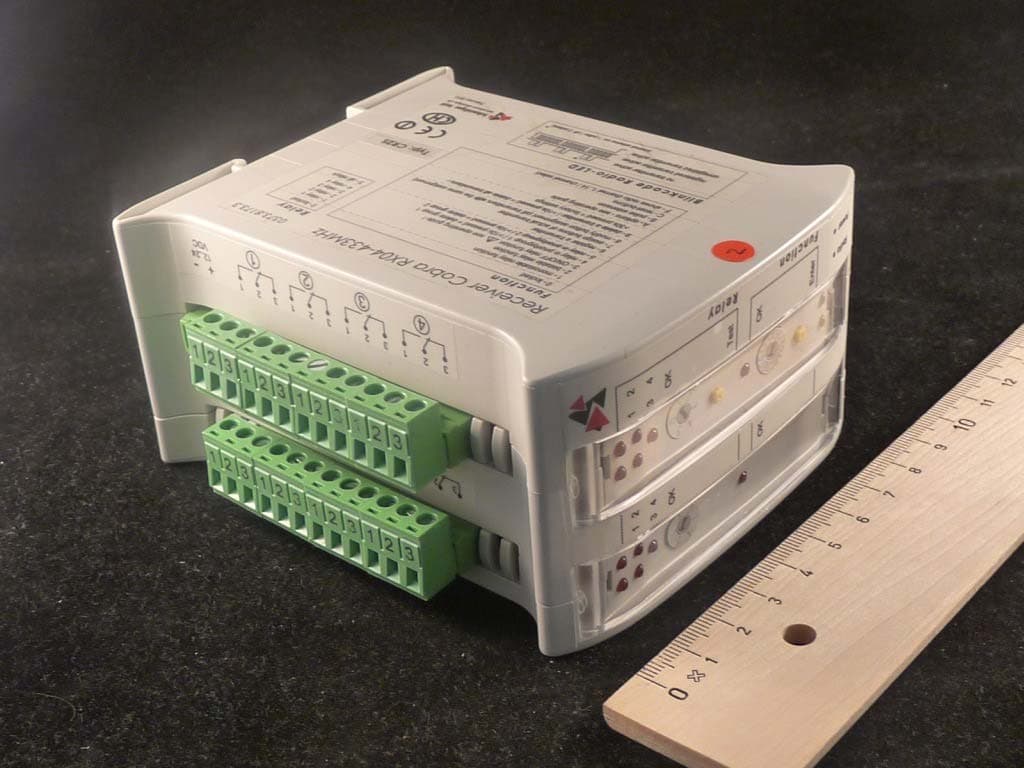
Click to zoom
Application Details
- Equipment Class
- JBP - Part 15 Class B Computing Device Peripheral
- Date of Grant
- Sep 30, 2014
- Application Purpose
- Original Equipment
- Date of Application
- Sep 30, 2014
- Equipment Note
- Cobra 100
- Company
- Schmidiger GmbH
- Country
- Switzerland
Documents & Files
Document Text
Text extracted from the exhibit documents filed with the FCC. Open a document above to read the original.
Users Manual
0053.0338.71 Cobra narrowband system Handheld transmitter CS4S / receiver CR2S User manual Version list Date Version Description 16.04.2007 1.0E Represents Software dated April 2007 02.06.2007 1.1E Translation of version 1.1 into English 22.08.2013 3.1E Translation of version 3.1 into English 26.06.2014 3.2E Translation of version 3.2 into English, FCC Compliances Cobra radio control system 1 Contents 1. SUMMARY ...................................................................................................................... 4 2. CHARACTERISTICS OF THE COBRA SYSTEM ........................................................... 4 General characteristics .................................................................................................................................. 4 Handheld transmitter ...................................................................................................................................... 4 Receiver ......................................................................................................................................................... 4 3. HANDHELD TRANSMITTER CS4S ................................................................................ 5 Summary ............................................................................................................................................... 5 Carrying possibilities .............................................................................................................................. 5 Belt clip ........................................................................................................................................................... 5 Belt loop ......................................................................................................................................................... 5 Display ................................................................................................................................................... 6 Keys ....................................................................................................................................................... 7 Power supply / battery ........................................................................................................................... 7 Using of rechargeable batteries ................................................................................................................. 7 Battery power control ................................................................................................................................. 7 Extended transmitter functions .............................................................................................................. 8 DIP-switch (DSW) .......................................................................................................................................... 8 Standard (10K)....................................................................................................................................... 8 DoubleclickLock-20s (10K) .................................................................................................................... 8 DoubleClickLock (10K) .......................................................................................................................... 8 DoubleClickExtension (20K) .................................................................................................................. 8 OneKeyLock .......................................................................................................................................... 8 Autofrequency ........................................................................................................................................ 8 Configuration menu-10/10.............................................................................................................................. 9 Transmitter settings ................................................................................................................................. 10 Status display for relays 1 to 8............................................................................................................. 11 Status display for external input........................................................................................................... 11 Radio link acknowledgement with buzzer ............................................................................................ 11 STOP-function on the key .............................................................................................................. 12 Resistive keyboard monitoring ............................................................................................................. 12 Direct-Scan .......................................................................................................................................... 12 Radio link test mode ................................................................................................................................ 13 Changing LED-display for radio link test mode ................................................................................... 13 Disturbance .......................................................................................................................................... 13 Radio link quality .................................................................................................................................. 13 Currently frequency ............................................................................................................................. 14 Key test .................................................................................................................................................... 14 Configuration menu-7/12 (keyboard modification) .................................................…
Text truncated - open the document above for the full version.
External Photos
Test Laboratory: 7Layers AG Borsigstrasse 11 40880 Ratingen Germany Note: The following test results relate only to the devices specified in this document. This report shall not be reproduced in parts without the written approval of the test laboratory. 7 layers AG Aufsichtsratsvorsitzender Registergericht registered in: Borsigstrasse 11 Chairman of the Supervisory Board: Düsseldorf, HRB 44096 40880 Ratingen, Germany Peter Mertel USt-IdNr VAT No.: Phone: +49 (0) 2102 749 0 Vorstand Board: DE 203159652 Fax: +49 (0) 2102 749 350 Dr. H.-J. Meckelburg TAX No. 147/5869/0385 www.7Layers.com Dr. H. Ansorge Photo Report on External Photos Report Reference: MDE_SCHMI_1301_RX_External_Photos Version: 2014-09-30 FCC ID: 2AB65COBRA100RXCR2S Report Reference: MDE_SCHMI_1301_RX_External_Photos Page 2 of 8 Photo 1: Master Module + Slave Module Report Reference: MDE_SCHMI_1301_RX_External_Photos Page 3 of 8 Photo 2: Master Module + Slave Module Report Reference: MDE_SCHMI_1301_RX_External_Photos Page 4 of 8 Photo 3: Master Module + Slave Module Report Reference: MDE_SCHMI_1301_RX_External_Photos Page 5 of 8 Photo 4: Master Module + Slave Module Report Reference: MDE_SCHMI_1301_RX_External_Photos Page 6 of 8 Photo 5: Master Module Report Reference: MDE_SCHMI_1301_RX_External_Photos Page 7 of 8 Photo 6: Master Module Report Reference: MDE_SCHMI_1301_RX_External_Photos Page 8 of 8 Photo 7: Master Module
ID Label/Location Info
Cobra 100 FCC-certification Schmidiger GmbH equipment label_RX_FCC ID.docx 1 07.04.2014 / FK equipment label (receiver) FCC ID: The receiver is labeled with waterproof labels. FCC ID: 2AB65COBRA100RXCR2S etiquette (Zweckform: L7567) printed with laser printer original size: labeling_RX.pdf FCC ID: 2AB65COBRA100RXCR2S This device complies with part 15 of the FCC Rules. Operation is subject to the following two conditions: (1) This device may not cause harmful interference, and (2) this device must accept any interference received, including interference that may cause undesired operation.
Internal Photos
Test Laboratory: 7Layers AG Borsigstrasse 11 40880 Ratingen Germany Note: The following test results relate only to the devices specified in this document. This report shall not be reproduced in parts without the written approval of the test laboratory. 7 layers AG Aufsichtsratsvorsitzender Registergericht registered in: Borsigstrasse 11 Chairman of the Supervisory Board: Düsseldorf, HRB 44096 40880 Ratingen, Germany Peter Mertel USt-IdNr VAT No.: Phone: +49 (0) 2102 749 0 Vorstand Board: DE 203159652 Fax: +49 (0) 2102 749 350 Dr. H.-J. Meckelburg TAX No. 147/5869/0385 www.7Layers.com Dr. H. Ansorge Photo Report on Internal Photos Report Reference: MDE_SCHMI_1301_RX_Internal_Photos Version: 2014-09-16 FCC ID: 2AB65COBRA100RXCR2S Report Reference: MDE_SCHMI_1301_RX_Internal_Photos Page 2 of 6 Photo 1: Bottom side of Master and Slave Module Report Reference: MDE_SCHMI_1301_RX_Internal_Photos Page 3 of 6 Photo 2: Top side of Slave Module Report Reference: MDE_SCHMI_1301_RX_Internal_Photos Page 4 of 6 Photo 3: Top side of Master Module with transceiver board and antenna Report Reference: MDE_SCHMI_1301_RX_Internal_Photos Page 5 of 6 Photo 4: Transceiver board with shielding Report Reference: MDE_SCHMI_1301_RX_Internal_Photos Page 6 of 6 Photo 5: Transceiver board without shielding (top side) Photo 6: Transceiver board (bottom side)
Test Report
Final Report on Slave Module Cobra 100 and Master Module Cobra100RxCR2S (Remote Control Transceiver 433 MHz) FCC ID: 2AB65COBRA100RXCR2S MDE_SCHMI_1301_FCCc accordin g to FCC Part 15, subpart B Re port Reference: Se ptember 09, 2014Date: Test Laboratory: 7Layers AG Borsigstr. 11 40880 Ratingen Germany Note: The following test results relate only to the devices specified in this document. This report shall not be reproduced in parts without the written approval of the test laboratory. 7Layers AG Aufsichtsratsvorsitzender Registergericht registered in: Borsigstrasse 11 Chairman of the Supervisory Board:Düsseldorf, HRB 44096 40880 Rat ingen, Germany Peter Mertel USt-IdNr VAT No.: Phone: +49 (0) 2102 749 0Vorstand Board: DE 203159652 Fax: +49 (0) 2102 749 350 Dr. H.-J. Meckelburg TAX No. 147/5869/0385 www.7Layers.com Dr. H. Ansorge Reference: MDE_SCHMI_1301_FCCc according to FCC Part 15, subpart B 2.2Detailed Description of OUT Samples Sample : m_bb01 OUT Identifier Sample Description HW Status SW Status High Voltage Cobra 100 Master module (Transceiver) Master Module with 4 relays A 15 14 10 51 12 -- Normal Temp.Nominal Voltage -- 25 °C Sample : s_BB01 OUT Identifier Sample Description HW Status SW Status High Voltage Cobra 100 Slave module Slave Module providing 4 additional relays B 14 14 10 46 12 24 V Normal Temp.Nominal Voltage12 V25 °C 2.3OUT Features Supported Features for OUT:Cobra 100 Master module DesignationDescriptionSupported Value(s) Features for scope: FCC_v2 The OUT is powered by or connected to AC Mains via a power supply AC SRD Highest Frequency: EUT is a short range device 16 MHz Clock Supported Features for OUT:Cobra 100 Slave module DesignationDescriptionSupported Value(s) Features for scope: FCC_v2 AC The OUT is powered by Master Module SRDEUT is a short range device 2.4Auxiliary Equipment AE No.Serial No.SW StatusHW StatusDescriptionType Designation AE 02Fujitsu LIFEBOOK E Series E781 DSCK013817Laptop RE AE 01LG L17NB-3504WAHS3J991EMC TFT 2 AE 04Logitech M-BT58HC60915A2XCEMC MOUSE 1 AE 05Logitech Ultrax Media Keyboard ST635J01624Keyboard 2 AE 03SED100P2-19.007Y17323AAC Adapter 2 Laptop RE Page 4 of 24 The Cobra 100 Slave module is phyiscally connected to the Master module in order to extend the amout of relays available. The Slave Module cannot be operated independed from the Master Module Reference: MDE_SCHMI_1301_FCCc according to FCC Part 15, subpart B 2.5Setups used for Testing For each setup a relation is given to determine if and which samples and auxiliary equipment is used. The left side list all OUT samples and the right side lists all auxiliary equipment for the given setup. Sample No.Sample DescriptionAE No.AE Description Setup No.List of OUT samplesList of auxiliary equipment PC_BB01 (Computer Peripheral) AE 02Laptop REm_bb01Master Module with 4 relays Sample: AE 01EMC TFT 2s_BB01Slave Module providing 4 additio Sample: AE 04EMC MOUSE 1 AE 05Keyboard 2 AE 03AC Adapter 2 Laptop RE 3Results 3.1General Available at the test laboratory. The results of the inspection are described on the following pages, where 'Conformity' or 'Passed' means that the certification criteria were verified and that the tested device is conform to the applied standard. In cases where 'Declaration' is printed, the required documents are available in the manufacturers product documentation. In cases where 'not applicable' is printed, the test case requirements are not relevant to the specific equipment implementation. Documentation of tested devices: Interpretation of the test results: 1. Thi s report contains the abbreviated information co ntent pertai ning to services rendered. Supporting documentation not included herein is maintained and available at the laboratory. 2. Al l tests are performed under environmental conditions within the requirements of the specifications. Environmental conditions are available at the laboratory. Note: 3.2List of the Applicable Body (Body for Scope: FCC_v2) DesignationDescription Part 15, Subpart B - Unintentional RadiatorsFCC47CFRChIPART15bRADIO FREQUENCY DEVICES 3.3List of Test Specification Test Specification:FCC part 2 and 15 Version10-1-13 Edition Title:PART 2 - GENERAL RULES AND REGULATIONS PART 15 - RADIO FREQUENCY DEVICES Page 5 of 24 Reference: MDE_SCHMI_1301_FCCc according to FCC Part 15, subpart B 3.4Summary Test Case Identifier / Name SetupDate of TestVerdictTest (condition)Ref. Lab 15b.1 Conducted Emissions (AC Power Line) §15.107 15b.1; Mode = generating a high power consumption 2014/05/08PC_BB01Lab 1Passed 15b.2 Spurious Radiated Emissions §15.109 15b.2; Mode = generating a high power consumption 2014/05/07PC_BB01Lab 2Passed Page 6 of 24 Reference: MDE_SCHMI_1301_FCCc according to FCC Part 15, subpart B 3.5Detailed Results 3.5.115b.1 Conducted Emissions (AC Power Line) §15.107 Test: 15b.1; Mode = generating a high power consumption Result:Passed Setup No.:PC_BB01 Date of Test:2014/05/08 9:36 Body:FCC47CFRChIPART15bRADIO FREQUENCY DEVICES Test Specification:FCC part 2 and 15 Page 7 of 24 Reference: MDE_SCHMI_1301_FCCc according to FCC Part 15, subpart B Detailed Results: AC MAINS CONDUCTED EUT: (DE1033000bb01) Manufacturer: Schmidiger Operating Condition: TX on 434.725 MHz, data traffic on RS232-cable (Micro-Match to USB) Test Site: 7 layers Ratingen Operator: Doe Test Specification: ANSI C63.4; FCC 15.107 / 15.207 Comment: Co nnected to 120V/60HZ AC via power supply, computer peripheral setup Start of Test: 08.05.2014 / 23:02:57 SCAN TABLE: "FCC Voltage" Short Description: FCC Voltage Start Stop Step Detector Meas. IF Transducer Frequency Frequency Width Time Bandw. 150.0 kHz 30.0 MHz 5.0 kHz MaxPeak 20.0 ms 9 kHz ESH3-Z5 Average 0 10 20 30 40 50 60 70 80 Level [dBμV] 150k300k500k1M2M3M5M 7M 10M30M Frequency [Hz] MES SCH_1301_021_pre PK MES SCH_1301_021_pre AV LIM FCC 15b QP volt Voltage QP Limit LIM FCC 15b AV volt Voltage QP Limit Page 8 of 24 Reference: MDE_SCHMI_1301_FCCc according to FCC Part 15, subpart B 3.5.215b.2 Spurious…
Text truncated - open the document above for the full version.
Test Setup Photos
Test Laboratory: 7Layers AG Borsigstrasse 11 40880 Ratingen Germany Note: The following test results relate only to the devices specified in this document. This report shall not be reproduced in parts without the written approval of the test laboratory. 7 layers AG Aufsichtsratsvorsitzender Registergericht registered in: Borsigstrasse 11 Chairman of the Supervisory Board: Düsseldorf, HRB 44096 40880 Ratingen, Germany Peter Mertel USt-IdNr VAT No.: Phone: +49 (0) 2102 749 0 Vorstand Board: DE 203159652 Fax: +49 (0) 2102 749 350 Dr. H.-J. Meckelburg TAX No. 147/5869/0385 www.7Layers.com Dr. H. Ansorge Photo Report on Test Setups For report MDE_SCHMI_1301_FCCc Report Reference: MDE_SCHMI_1301_FCCc_Setup_Photos Version: 2014-08-08 FCC ID: 2AB65COBRA100RXCR2S Test report Reference: MDE_SCHMI_1301_FCCc_Setup_Photos Page 2 of 5 Photo 1: Test setup for conducted measurements at DC port (power line) EUT supplied by stabilized AD/DC power supply Computer peripheral setup unintentional radiator §15 Test report Reference: MDE_SCHMI_1301_FCCc_Setup_Photos Page 3 of 5 Photo 2: Test setup for conducted measurements at DC port (power line) EUT supplied by stabilized AD/DC power supply Computer peripheral setup unintentional radiator §15 Test report Reference: MDE_SCHMI_1301_FCCc_Setup_Photos Page 4 of 5 Photo 3: Test setup for radiated measurements, EUT in horizontal position EUT supplied by stabilized AD/DC power supply Computer peripheral setup Semi-anechoic chamber, 30 MHz to 1 GHz unintentional radiator §15 Test report Reference: MDE_SCHMI_1301_FCCc_Setup_Photos Page 5 of 5 Photo 4: Test setup for radiated measurements, EUT in horizontal position EUT supplied by stabilized AD/DC power supply Computer peripheral setup Semi-anechoic chamber, 30 MHz to 1 GHz unintentional radiator §15
Contact Information
Applicant
Fabian Kugler
Technical Contact
Non-Technical Contact
7 Layers AGBernhard Retka
Test Firm
7layers AGRobert Machulec
Technical Specifications
| # | Rule Parts | Frequency Range | Power Output |
|---|---|---|---|
| 1 | 15B | - | - |
Other Applications from Schmidiger GmbH
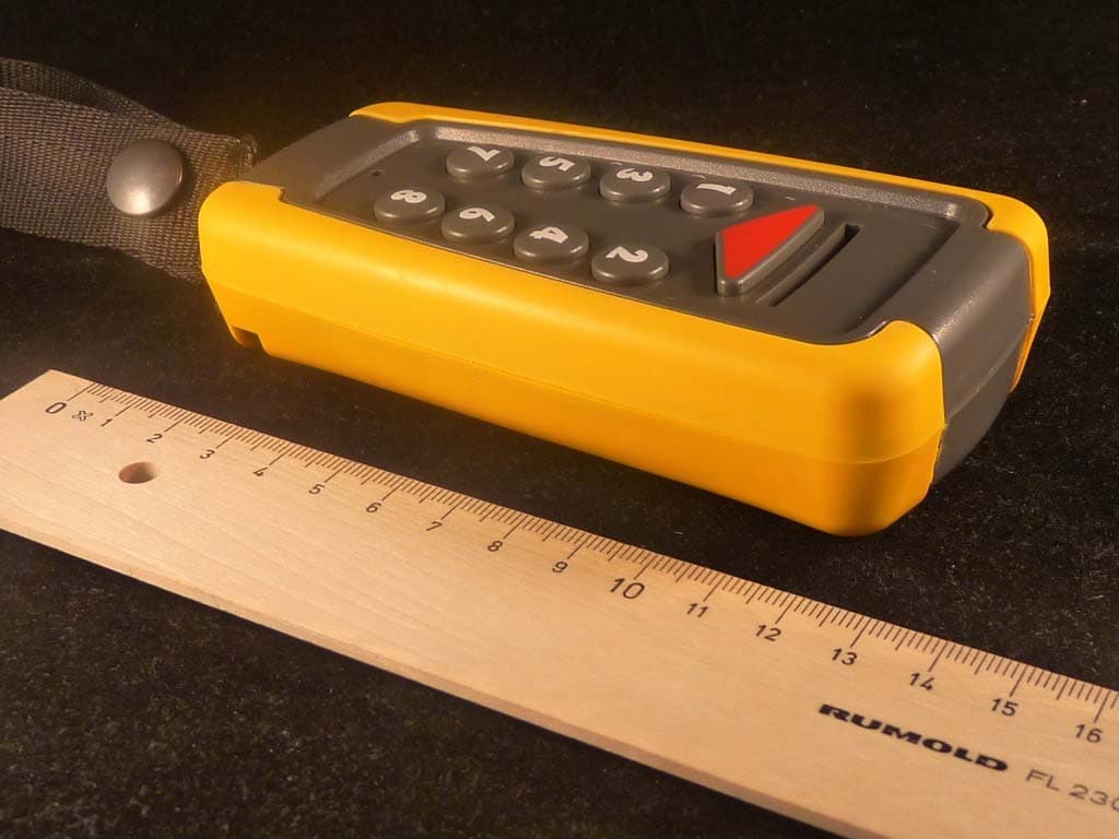
2AB65COBRA100TXCS4S
Aug 21, 2014Cobra 100
Equipment Class
DSR - Part 15 Remote Control/Security Device Transceiver