Text extracted from the exhibit documents filed with the FCC. Open a document above to read the original.
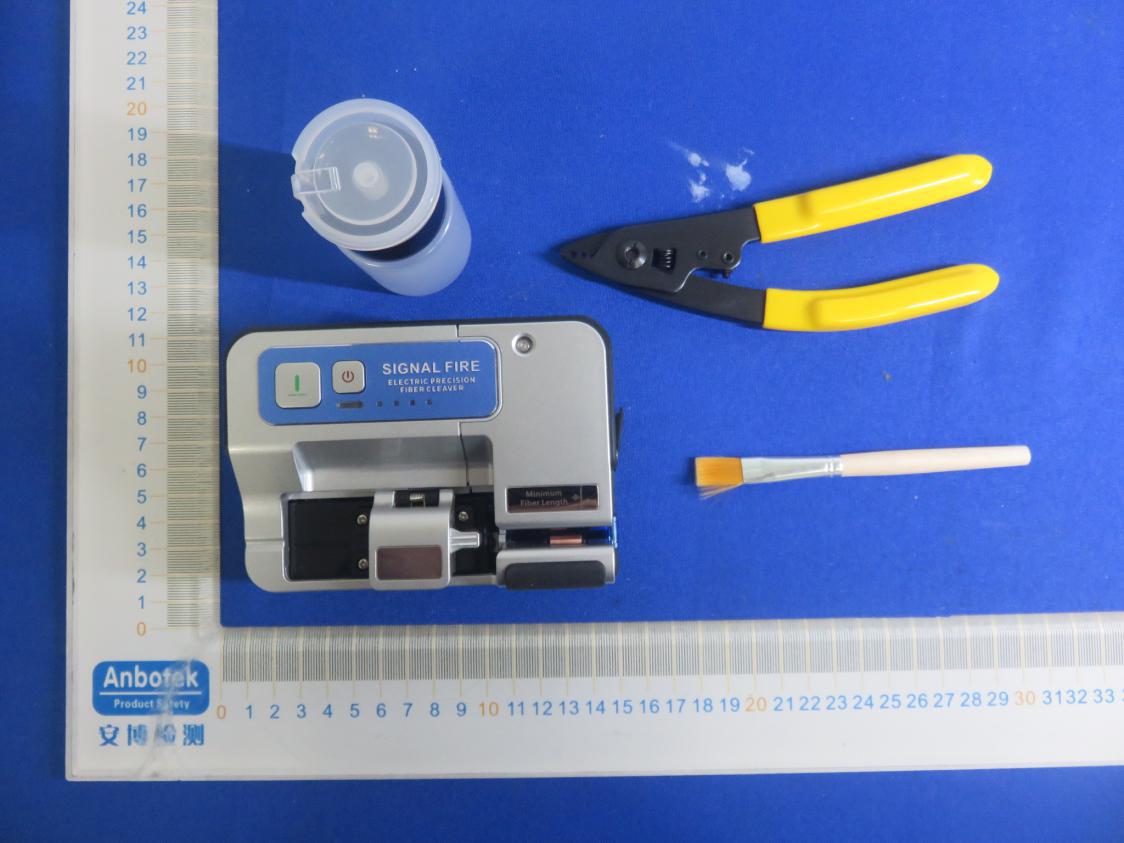
USER'S MANUAL 2020/09 SF-10 OPTICAL FIBER CLEAVER Electric precision SF-10 OPTICAL FIBER CLEAVER Electric precision 01 02 03 05 12 15 Warnings and Precautions Basic Information Appearance Operation instructions Maintenance Common problems and solutions CATALOGUE This equipment complies with FCC radiation exposure limits set forth for an uncontrolled environment. This equipment should be installed and operated with minimum distance 20cm between the radiator & your body. FCC Radiation Exposure Statement:FCC STATEMENT : Reorient or relocate the receiving antenna. Increase the separation between the equipment and receiver.Connect the equipment into an outlet on a circuit different from that to which thereceiver is connected. Consult the dealer or an experienced radio/TV technician for help. This device complies with Part 15 of the FCC Rules. Operation is subject to the followingtwo conditions: (1) This device may not cause harmful interference, and (2) This device must accept any interference received, including interference that maycause undesired operation. Warning: Changes or modifications not expressly approved by the party responsible for compliance could void the user's authority to operate the equipment. NOTE: This equipment has been tested and found to comply with the limits for a Class B digital device, pursuant to Part 15 of the FCC Rules. These limits are designed to provide reasonable protection against harmful interference in a residential installation. This equipment generates uses and can radiate radio frequency energy and, if not installed and used in accordance with the instructions, may cause harmful interference to radiocommunications. However, there is no guarantee that interference will not occur in a particular installation. If this equipment does cause harmful interference to radio or television reception, which can be determined by turning the equipment off and on, the user is encouraged to try to correct the interference by one or more of the following measures: SF-10 0102 Basic Information Please read this manual carefully before operating the equipment. Follow all safety instructions and warnings contained in this manual. Warnings and Precautions OPTICAL FIBER CLEAVER Electric precision Accessories list: Host :1 set/Miller stripper :1 piece /alcohol bottle :1 set/Instruction :1 copy/ Type-C charging cable :1 set Warning: If this document is ignored, it may cause personal injury or damage to the equipment due to improper use. Safety glasses should always be worn during fiber preparation and cutting. If fiber fragments come into contact with the skin or eyes, there is a risk of personal injury. Attention: 1.Do not disassemble or modify the fiber cleaver. 2.The fiber cleaver is designed for cutting glass fibers used in communications, do not attempt to cut any other material. 3.The cutting blade is very sharp, please do not touch it, otherwise it may cause personal injury. 4.Never expose the fiber cleaver to rain or moisture. SF-10 OPTICAL FIBER CLEAVER Electric precision Bluetooth for wireless communication The SF-10 carries out wireless communication through 2.4g Bluetooth, and the Bluetooth is automatically turned on when starting Fiber type Cut length Cutting Angle Bare machine size Bare-metal weight charging voltage Working environment single-mode/multi-mode fiber: Diameter: 80um-220um (rubber-covered wire, tail fiber, fiber optic cable) Bare fiber: 3-25mm/rubber-covered wire& tail fiber: 10-25mm Mean < 0.5° 122mmX87mmX67mm 630g DC5V/2A Temperature: -10 to 40°C / humidity: 0 to 95% 0304 Bluetooth connection indicator Put the fiber line in the shortest way Waste fiber box Type-C charging interface 1.Fiber cutting (Manual mode) 2.If the fiber cleaver is not in the normal position, press 1.5 seconds to reset the fiber cleaver The Bluetooth connection is successful and the indicator light is on Remove the screw and replace the blade Power indicator. Long press the power button for one second to show the current power level Optical fiber holder Brush for clean Power switch SF-10 Appearance Appearance OPTICAL FIBER CLEAVER Electric precision SF-10 OPTICAL FIBER CLEAVER Electric precision 0506 The position of the stripped coated fiber is placed Rubber-covered Wireoptical Fiber Placement Position Position of tail fiber Bare fiber Rubber-covered Wire Tail fiber 1.Peel off the 28-33mm coating and wipe the fiber clean with alcohol. 2.Put the clean fiber into the holder base and pay attention to the position of the coating layer. 3.Close the cover of the holder and the fiber cleaver will automatically cut (Automatic cutting function will be turned on by App default) Open by default SF-10 Operation instructions Operation instructions OPTICAL FIBER CLEAVER Electric precision SF-10 OPTICAL FIBER CLEAVER Electric precision 1.Peel off 33-38mm of the outer plastic skin of therubber-covered wire with stripping pliers, and then peel off 28-33mm of the optical fiber the coating is wiped with alcohol to clean the fiber. 2.Put the clean optical fiber into the holder base. Note the position of the plastic skin shown in the figure 1.The outer plastic skin of the tail fiber is stripped off 33-38mm with Miller stripper, and the strengthened velvet is cut off with scissors. Then the middle plastic skin is stripped off 28- 33mm with Miller stripper. Finally, the fiber coating of 28-33mm is stripped off with the smallest mouth of Miller stripper, and the fiber is wiped clean with alcohol. 2.Put the clean optical fiber into the holder base. Note the position of the plastic skin shown in the figure. 0708 Manual cutting: Place the prepared optical fiber, press the cutting button on the fiber cleaver or the "Cutting Optical fiber" button on the APP, and the fiber cleaver will cut the optical fiber by itself. Manually cut optical fiber button (long press 1.5 seconds to reset the fiber cleaver) The two buttons here are equivalent to the cutting button function on the machine Fiber waste disposal: Pā¦
Text truncated - open the document above for the full version.
FCCID:2AB9B-SF10
LabelLocationOnEUT Label ProductName:ELECTRICPRECISIONFIBERCLEAVER ModelNo.:SF-10 FCCID:2AB9B-SF10 ThisdevicecomplieswithPart15oftheFCCRules.Operationis subjecttothefollowingtwoconditions: (1)Thisdevicemaynotcauseharmfulinterference,and (2)Thisdevicemustacceptanyinterferencereceived,including interferencethatmaycauseundesiredoperation.
FCCID:2AB9B-SF10 ANT
version01 SignalFireTechnologyCo.,Ltd. DeclarationconcerningAntennaSpecification Itisherebydeclaredthattheproduct ModelNo.:SF-10,SF-11 FCCID:2AB9B-SF10 fulfillstherequirementinFCCtestrelatingtotheantennatype. ThedevicespecifiedaboveconfirmstotheFCCrecommendationsforinternalantennatype(s) describedbelow: ModelNo.ofantenna:N/A Typeofantenna:PCBAntenna Gainoftheantenna:-3dBi Frequencyrange:2402~2480MHz Themountingoftheantennaisfixedtotheradiomoduleandnootherantennashouldbeused. Companyname:SignalFireTechnologyCo.,Ltd. Address:No.B-6QingyangZone,JiaolongIndustrialParkQingyangDistrict, Chengdu,China City: Chengdu ZIP/Postalcode: / Country: China Place: Chengdu,ChinaDate:2/27/2021 Signature:
RF EXPOSURE EVALUATION FCC ID: 2AB9B-SF10 According to FCC 1.1310: The criteria listed in the following table shall be used to evaluate the environment impact of human exposure to radio frequency(RF) Radiation as specified in §1.1307(b): Routine SAR evaluation refers to that specifically required by §2.1093, using measurements or computer simulation. When routine SAR evaluation is not required, portable transmitters with output power greater than the applicable low threshold require SAR evaluation to qualify for TCB approval. Channel (MHz) Maximum output power (dBm) Tune up tolerance (dBm) Max Tune Up Power (dBm) Distance (mm) Calculation results Limit Operating Mode 2402-0.350-0.350±1 0.65 5 0.360 3 24400.1670.167 ±11.167 5 0.409 3 24802.2812.281±13.28150.6703 Test Results:PASS.
Report No.: 18220WC10014001FCC ID: 2AB9B-SF10Page 1 of 54 FCC TEST REPORT Client Name:Signal Fire Technology Co., Ltd. Address: No.B-6 Qingyang Zone, Jiaolong Industrial Park Qingyang District, Chengdu, China Product Name:ELECTRIC PRECISION FIBER CLEAVER Date:Feb. 27, 2021 Shenzhen Anbotek Compliance Laboratory Limited Report No.: 18220WC10014001FCC ID: 2AB9B-SF10Page 2 of 54 Contents 1. General Information ............................................................................................................................................... 5 1.1. Client Information ....................................................................................................................................... 5 1.2. Description of Device (EUT) ..................................................................................................................... 5 1.3. Auxiliary Equipment Used During Test ................................................................................................... 6 1.4. Description of Test Modes ........................................................................................................................ 6 1.5. List of channels ........................................................................................................................................... 6 1.6. Description Of Test Setup ......................................................................................................................... 7 1.7. Test Equipment List .................................................................................................................................... 8 1.8. Measurement Uncertainty ......................................................................................................................... 9 1.9. Description of Test Facility ........................................................................................................................ 9 2. Summary of Test Results ................................................................................................................................... 10 3. Conducted Emission Test ................................................................................................................................... 11 3.1. Test Standard and Limit .......................................................................................................................... 11 3.2. Test Setup .................................................................................................................................................. 11 3.3. Test Procedure .......................................................................................................................................... 11 3.4. Test Data .................................................................................................................................................... 11 4. Radiation Spurious Emission and Band Edge ................................................................................................ 16 4.1. Test Standard and Limit .......................................................................................................................... 16 4.2. Test Setup .................................................................................................................................................. 16 4.3. Test Procedure .......................................................................................................................................... 17 4.4. Test Data .................................................................................................................................................... 18 5. Maximum Peak Output Power Test .................................................................................................................. 26 5.1. Test Standard and Limit .......................................................................................................................... 26 5.2. Test Setup .................................................................................................................................................. 26 5.3. Test Procedure .......................................................................................................................................... 26 5.4. Test Data .................................................................................................................................................... 26 6. 6DB Occupy Bandwidth Test ............................................................................................................................. 29 6.1. Test Standard and Limit .......................................................................................................................... 29 6.2. Test Setup .................................................................................................................................................. 29 6.3. Test Procedure .......................................................................................................................................... 29 6.4. Test Data .................................................................................................................................................... 29 7. Power Spectral Density Test .............................................................................................................................. 32 7.1. Test Standard and Limit .......................................................................................................................... 32 7.2. Test Setup .................................................................................................................................................. 32 7.3. Test Procedure .......................................................................................................................................... 32 7.4. Test Data ...ā¦
Text truncated - open the document above for the full version.
FCCID:2AB9B-SF10 PhotoofPowerLineConductedEmissionTest PhotoofRadiationEmissionTest
| # | Rule Parts | Frequency Range | Power Output |
|---|---|---|---|
| 1 | 15C | 2.40 GHz - 2.48 GHz | 1.70 mW |
OPTICAL FIBER FUSION SPLICER
Equipment Class
DTS - Digital Transmission System