2ABD6AL24GMPBDPPoint to Point radio
ALCOMA a.s.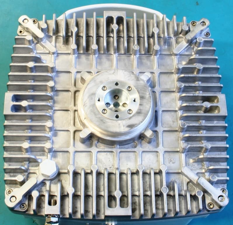
Click to zoom
Application Details
- Equipment Class
- DXX - Part 15 Low Power Communication Device Transmitter
- Date of Grant
- Mar 10, 2014
- Application Purpose
- Original Equipment
- Date of Application
- Mar 10, 2014
- Equipment Note
- Point to Point radio
- Frequency Range
- 24050.00000000 - 24250.00000000
- Company
- ALCOMA a.s.
- Country
- Czech Republic
Documents & Files
Document Text
Text extracted from the exhibit documents filed with the FCC. Open a document above to read the original.
Users Manual
Microwave data link ZENITH 24 License free frequency band 24 GHz Installation and operation manual Document version: 1.2 Published: 10. 2. 2011 Last modification: 8. 1. 2014 www.alcoma.com CONTENTS page 1. INTRODUCTION .................................................................................................................................1 1.1 BASIC DATA...........................................................................................................................................................3 2. DESCRIPTION OF THE LINK.................................................................................................................5 2.1 TX POWER REGULATION..........................................................................................................................................7 2.2 PROTECTED TERMINAL BOX......................................................................................................................................7 2.2.1 Input Connectors...........................................................................................................................................9 2.2.2 Output Connectors......................................................................................................................................10 2.2.3 Indication ....................................................................................................................................................11 2.2.4 Jumpers ‐ without function for the S‐STP Cat7 cable..................................................................................11 2.3 THE ODU OUTDOOR UNIT....................................................................................................................................12 2.3.1 Input Connectors.........................................................................................................................................13 2.3.2 Indication ....................................................................................................................................................15 2.3.3 Rotary function switch................................................................................................................................15 3. INSTALLATION INSTRUCTIONS.........................................................................................................16 3.1 EVALUATION OF SUITABLE PLACEMENT.....................................................................................................................16 3.2 PLACEMENT OF THE ANTENNA ON A SUPPORT CONSTRUCTION.......................................................................................16 3.3 DUAL POLARIZATION OF RADIO LINK......................................................................................................................18 3.4 LOCAL FREQUENCY COORDINATION..........................................................................................................................19 3.5 RADIATOR INSTALLATION.......................................................................................................................................19 3.6 INSTALLATION OF THE ANTENNA SYSTEM..................................................................................................................21 3.7 RADIO LINK INSTALLATION......................................................................................................................................22 3.7.1 The AL2‐xx/ME antenna type (also for the AL1‐xx/ME)................................................................................1 3.7.2 The AL3‐xx/MP antenna type (also for the AL4‐xx/MP)..............................................................................23 3.8 GROUNDING.......................................................................................................................................................25 3.9 MANIPULATION WITH THE USER SPACE COVER..........................................................................................................26 3.10 INSTALLATION OF INTERCONNECT CABLE...................................................................................................................27 3.10.1 The procedure during installation of ACOME cable type Cat 7 S‐STP .........................................................27 3.11 OPTIONAL SFP MODULES......................................................................................................................................29 3.12 INSTALLING AN OPTICAL CONNECTOR MOLEX 106059 ..............................................................................................30 3.13 BEFORE PUTTING THE RADIO LINK INTO OPERATION....................................................................................................31 3.14 ACCESSORIES.......................................................................................................................................................31 4. SETTING OF THE RADIO LINK AND ITS COMMISSIONING..................................................................33 4.1 ANTENNA POINTING..............................................................................................................................................33 4.1.1 Pointing Procedure:.....................................................................................................................................34 4.1.2 Rough Adjustment ......................................................................................................................................34 4.1.3 The pointing of radio link with the AL2‐xx/ME (also for AL1‐xx/ME)..........................................................35 4.1.4 The pointing of radio link with the AL3‐xx/MP antenna (also for the AL4‐xx/MP antenna).......................36 4.2 CHANGE OF POLARIZATION.......................................................................................................…
Text truncated - open the document above for the full version.
Block Diagram
Block schematic of ALCOMA ZENITH 24 link
Operational Description
OPERATIONAL DESCRIPTION The radio relay link ZENITH 24 station consists of three main parts: 1. The outdoor microwave unit that is integral with the antenna contains: The RF block that includes the microwave receiver, power amplifier, and oscillators controlled by the phase‐lock loop. The data block that includes GEth 1000/100/10 switches, a modem and the monitoring system supervised by a controller. The power supply block that consists of DC‐DC transformers that power the whole station. This complete block has been designed on one printed circuit board (PCB) which removed a lot of circuits and thus significantly increased reliability. (Then there is the outdoor microwave unit called ODU ‐ Outdoor unit for short in the text.) 2. The antenna set with the parabolic antenna, the radiator and the pole attachment. 3. Considering placement of the data block in ODU, the station ZENITH 24 has an indoor unit reduced to the protected terminal box ALS1‐GEth (RP) or ALS1‐2GEth (RP) that ensures transmission of customer data, powering of the station, and protection against the atmospheric origin overvoltage and overcurrent. (The protected terminal box is marked as ALS1x in the further text.) ODU can be connected to the microwave parabolic antennas of the types ALCOMA AL1‐ xx/ME,(∅ 0.35 m), AL2‐xx/ME (∅ 0.65 m), AL3‐xx/MP (∅ 0.90 m), and AL4‐xx/MP (∅ 1.20 m). These antennas are standard equipped by icing protection (OPN) for use in demanding climatic conditions. The simply removable ODU is integrated with the antenna system into one compact whole. Interconnection between the protected terminal box and ODU is done by a double shielded outside cable (S‐STP Cat 7) with 4 pairs of conductors with the 100 Ω impedance. The link cable transmits customer data, powering for ODU and ODU monitoring signals.
Test Report
www.nemko.com Nemko Canada Inc., a testing laboratory, is accredited by the Standards Council of Canada. The tests included in this report are within the scope of this accreditation FCC 15.249 and RSS-210 A12.docx; Date: August 2013 SCC Accredited LAB LAB Accrédité CCN TM ONE WORLDOURAPPROVAL Test report 237982-2TRFWL Date of issue: January 21, 2014 Applicant: ALCOMA a.s. Product: Alcoma-Point to point microwave radios Model: ZENITH24 FCC ID: IC Registration number: 2ABD6AL24GMPBDP 11582A- AL24GMPBDP Specifications: FCC 47 CFR Part 15 Subpart C, §15.249 Operation in the 902–928 MHz, 2400–2483.5 MHz, 5725–5875 MHz and 24.0–24.25 GHz RSS-210, Issue 8, December 2010, Annex 12 Fixed Point-to-Point Systems in the Band 24.05–24.25 GHz Report reference ID: 237982-2TRFWL Page 2 of 36 Test location Company name: Nemko Canada Inc. Address: 303 River Road City: Ottawa Province: Ontario Postal code: K1V 1H2 Country: Canada Telephone: +1 613 737 9680 Facsimile: +1 613 737 9691 Toll free: +1 800 563 6336 Website: www.nemko.com Site number: FCC: 176392; IC: 2040A-4 (3 m semi anechoic chamber) Tested by: Kevin Rose, Wireless/EMC Specialist Reviewed by: Andrey Adelberg, Senior Wireless/EMC Specialist Date: January 21, 2014 Signature: Limits of responsibility Note that the results contained in this report relate only to the items tested and were obtained in the period between the date of initial receipt of samples and the date of issue of the report. This test report has been completed in accordance with the requirements of ISO/IEC 17025. All results contain in this report are within Nemko Canada’s ISO/IEC 17025 accreditation. Copyright notification Nemko Canada Inc. authorizes the applicant to reproduce this report provided it is reproduced in its entirety and for use by the company’s employees only. Any use which a third party makes of this report, or any reliance on or decisions to be made based on it, are the responsibility of such third parties. Nemko Canada Inc. accepts no responsibility for damages, if any, suffered by any third party as a result of decisions made or actions based on this report. © Nemko Canada Inc. Report reference ID: 237982-2TRFWL Page 3 of 36 Table of Contents Section 1 Report summary .................................................................................................................................................................... 4 1.1 Applicant/ Manufacturer .................................................................................................................................................................... 4 1.2 Test specifications ............................................................................................................................................................................ 4 1.3 Statement of compliance ................................................................................................................................................................... 4 1.4 Exclusions......................................................................................................................................................................................... 4 1.5 Test report revision history ................................................................................................................................................................ 4 Section 2 Summary of test results ........................................................................................................................................................ 5 2.1 FCC Part 15 Subpart C – general requirements, test results ............................................................................................................. 5 2.2 FCC Part 15 Subpart C – Intentional Radiators, test results .............................................................................................................. 5 2.3 IC RSS-GEN, Issue 3, test results ..................................................................................................................................................... 5 2.4 RSS-210, Issue 8, test results ........................................................................................................................................................... 5 Section 3 Equipment under test (EUT) details ..................................................................................................................................... 6 3.1 Sample information ........................................................................................................................................................................... 6 3.2 EUT information ................................................................................................................................................................................ 6 3.3 Technical information ........................................................................................................................................................................ 6 3.4 Product description and theory of operation ...................................................................................................................................... 7 3.5 EUT exercise details ......................................................................................................................................................................... 7 3.6 EUT setup Figure .............................................................................................................................................................................. 7 Section 4 Engineering considerations ................................................................................................................................................. 8 4.1 Modifications incorporated in the EUT ........................................................................................................…
Text truncated - open the document above for the full version.
Test Setup Photos
www.nemko.com Nemko Canada Inc., a testing laboratory, is accredited by the Standards Council of Canada. The tests included in this report are within the scope of this accreditation setup photos.docx; Date: May 2013 SCC Accredited LAB LAB Accrédité CCN TM ONE WORLDOURAPPROVAL Setup photos 237982-3RADWL Date of issue: January 22, 2014 Applicant: ALCOMA a.s. Product: Alcoma-Point to point microwave radios Model: ZENITH24 FCC ID: IC Registration number: 2ABD6AL24GMPBDP 11582A- AL24GMPBDP Section 1: Setup Photo photos Report reference ID: 237982-3RADWL Page 2 of 4 Section 1. Setup Photos Section 1: Setup Photo photos Report reference ID: 237982-3RADWL Page 3 of 4 Section 1: Setup Photo photos Report reference ID: 237982-3RADWL Page 4 of 4
Contact Information
Applicant
Petr Vodicka(Sales Director)
Test Firm
Nemko Canada Inc. (Ottawa)Charles Neal
Technical Specifications
| # | Rule Parts | Frequency Range | Power Output |
|---|---|---|---|
| 1 | 15C | 24.05 GHz - 24.25 GHz | - |
Other Applications from ALCOMA a.s.
2ABD6AL80GMPBDP
Mar 17, 2014Point to Point radio link
Equipment Class
TNB - Licensed Non-Broadcast Station Transmitter