2ABHRMC2402Maestro Rechargeable System Mobile Charger
Enteromedics, Inc.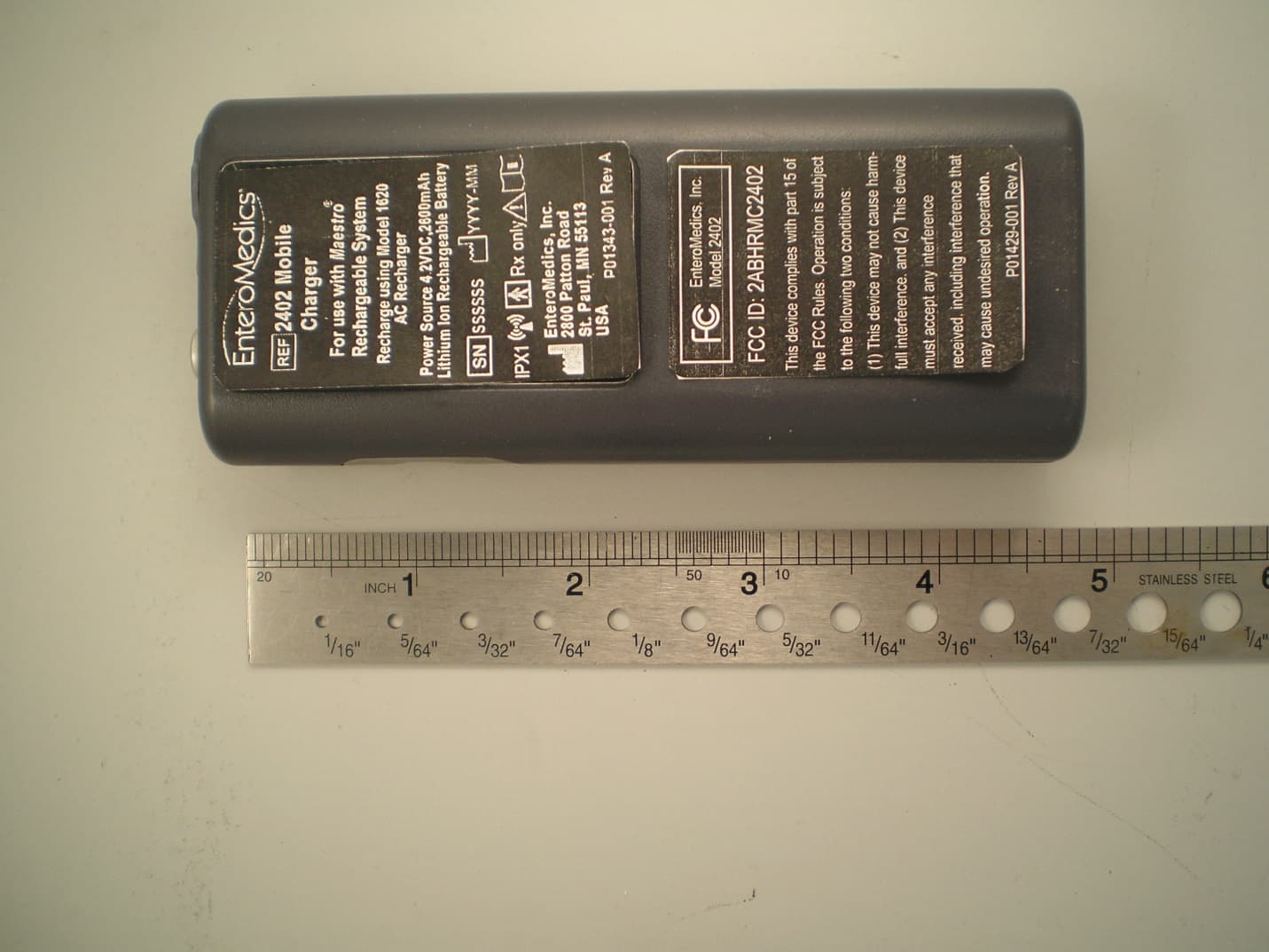
Click to zoom
Application Details
- Equipment Class
- DXX - Part 15 Low Power Communication Device Transmitter
- Date of Grant
- Mar 31, 2015
- Application Purpose
- Original Equipment
- Date of Application
- Mar 25, 2015
- Equipment Note
- Maestro Rechargeable System Mobile Charger
- Frequency Range
- 6.78000000 - 6.78000000
- Company
- Enteromedics, Inc.
- Country
- United States
Documents & Files
Document Text
Text extracted from the exhibit documents filed with the FCC. Open a document above to read the original.
Users Manual
Maestro ® Rechargeable System Instructions for Use CAUTION: Federal Law restricts this device to sale by or on the order of a physician. Copyright 2015 by EnteroMedics Inc., St. Paul, Minnesota All rights reserved EnteroMedics, VBLOC and Maestro are registered trademarks of EnteroMedics Inc. The Maestro System is protected under U.S., European, Japanese and Australian Patents, and patent applications. Subject to Pat. Nos.: AU2004209978; AU2009245845; AU2006280277; AU2006280278; AU2008226689; AU2008259917; AU2011265519; US 7,167,750; US 7,672,727; US 7,822,486; US 7,917,226; US 8,010,204; US 8,068,918; US 8,103,349; US 8,140,167; US 8,483,830; US 8,483,838; US 8,521,299; US 8,532,787; US 8,538,542; US 8,825,164; JP 5486588; EP 1601414; EP 1603634; EP 1922109; and EP1922111 For use in a method covered by Pat. Nos.: AU2009231601; US 7,489,969; US 7,729,771; US 7,613,515; US 7,844,338; US 8,046,085; US 8,538,533 Maestro ® Rechargeable System P01392-001 Rev K System Instructions for Use © EnteroMedics, Inc 2015 Page 2 of 73 Table of Contents 1. INDICATIONS FOR USE .................................................................................................................... 4 2. CONTRAINDICATIONS ..................................................................................................................... 5 3. WARNINGS ..................................................................................................................................... 6 4. PRECAUTIONS ................................................................................................................................. 8 5. DEVICE DESCRIPTION .................................................................................................................... 14 6. SYMBOLS & DEFINITIONS .............................................................................................................. 17 7. STORAGE, STERILIZATION & HANDLING ........................................................................................ 19 7.1 RE-STERILIZATION OR RE-USE OF MAESTRO RECHARGEABLE SYSTEM COMPONENTS .......................................... 20 7.2 ENVIRONMENT .................................................................................................................................... 20 8. POTENTIAL ADVERSE EVENTS ........................................................................................................ 21 9. CLINICAL STUDY ............................................................................................................................ 22 9.1 PRIMARY EFFICACY OBJECTIVES .............................................................................................................. 22 9.2 PRIMARY SAFETY OBJECTIVE .................................................................................................................. 22 9.3 SUBJECT DISPOSITION ........................................................................................................................... 22 9.4 PRIMARY SAFETY ENDPOINT ................................................................................................................... 24 9.4.1 All Serious Adverse Events ..................................................................................................... 25 9.4.2 Overview of All Adverse Events Related to Device, Therapy or Procedure ............................ 26 9.4.3 Adverse Events Leading to Study Withdrawal ....................................................................... 26 9.4.4 Surgical Removals of the Device ............................................................................................ 27 9.4.5 Surgical Revisions .................................................................................................................. 27 9.5 EFFECTIVENESS .................................................................................................................................... 27 9.5.1 Change in %EWL and %Total Body Weight Loss (%TBL) ........................................................ 28 9.5.2 Responder Analyses ............................................................................................................... 29 9.5.3 Improvements in Obesity Risk Factors ................................................................................... 29 9.6 UPDATED RESULTS THROUGH 18 MONTHS ............................................................................................... 30 10. INDIVIDUALIZATION OF TREATMENT ............................................................................................ 32 10.1 PATIENT SELECTION ......................................................................................................................... 32 10.2 USE IN SPECIFIC POPULATIONS ........................................................................................................... 32 10.3 PATIENT COUNSELING ...................................................................................................................... 32 11. OPERATING INSTRUCTIONS........................................................................................................... 33 11.1 USING THE MOBILE CHARGER ............................................................................................................ 37 11.2 MAESTRO RECHARGEABLE SYSTEM PREPARATION PRIOR TO IMPLANTATION ............................................... 39 12. IMPLANT PROCEDURE SUMMARY ................................................................................................ 43 Maestro ® Rechargeable System P01392-001 Rev K System Instructions for Use © EnteroMedics, Inc 2015 Page 3 of 73 13. LEAD STATUS (IMPEDANCE) TEST IN SURGERY .............................................................................. 46 14. DEVICE ACTIVATION AND TREATMENT INITIATION DURING SURGERY ......................................... 49 14.1 DEVICE ACTIVATION AND THERAPY INITIATION ..…
Text truncated - open the document above for the full version.
Cover Letter(s)
Federal Communications Commission Washington, D.C. 20554 November 20, 2009 DA 09-2425 Mitchell Lazarus Counsel for EnteroMedics Inc Fletcher, Heald & Hildreth, P.L.C. 1300 North 17 th Street, 11 th Floor Arlington, VA 22209 Dear Mr. Lazarus: This is in response to your request of October 6, 2008, filed on behalf of EnteroMedics™Inc. (EnteroMedics) for a waiver of Section 15.209 of the Commission’s Rules, 47 C.F.R. § 15.209, to permit EnteroMedics to obtain FCC certification for and market its Maestro™ RC and RF models of implantable medical devices. 1 You state that these devices are surgically implanted in the body and are used for the treatment of gastro-intestinal disorders such as obesity, diabetes, pancreatitis, and inflammatory bowel disease by disrupting communications between the vagus nerve and the brain. The implanted Maestro device receives both power and communications signals –either separately or simultaneously, depending on the model –from an external Controller that operates at a frequency of 6.78 MHz and is connected by a short cable to an external antenna attached to the skin. 2 The 6.78-MHz signal is centered in the 6.765-6.795MHz (6.78-MHz) industrial, scientific, and medical (ISM) band. 3 You also state that the Controller transmits a power signal on this frequency via the external antenna to the implanted device in compliance with the Commission’s Part 18 Rules for ISM equipment. 4 You further indicate that the Controller transmits a communications signal to the 1 SeeEnteroMedics Inc., Request for Waiver of Section 15.209 of the Commission’s Rules to Permit the Marketing of Implantable Devices for the Treatment of Gastro-Intestinal Disorders (Request) dated October 6, 2008, from Mitchell Lazarus, Fletcher, Heald & Hildreth, P.L.C. 2 SeeRequest at 1-2, 4-6. The RC model Controller operates in either “charging mode” or “programming mode,” but not at the same time. The RF model Controller simultaneously powers and programs the implanted device in real time but does not charge a battery. SeeRequest at 6. 3 The 6.78-MHz band –designated for ISM use –is part of the 6.765-7000 MHz band, which is allocated to fixed and mobile, except aeronautical mobile route, services on a primary basis for Federal and non- Federal users, and is authorized for Private Land Mobile radio services. In addition, under United States Footnote 340 (US340), the 2-30 MHz band is available on a non-interference basis to Federal and non- Federal maritime and aeronautical stations for the purpose of measuring the quality of reception on radio channels. See47C.F.R. §2.106, International Footnote 5.138, US340, and § 18.301. Under Part 18 of the Commission’s Rules, there is no power limit for in-band ISM operations in the 6.78-MHz ISM band. See 47 C.F.R. §18.305. Under Part15 of the Commission’s Rules, unlicensed intentional radiators may also be operated in the 6.78-MHz band. See47C.F.R. § 15.209. 4 When the RC Controller is charging the implanted device’s battery, its operation complies with Part 18. When the RF Controller’s signal is not modulated (i.e., no communications are transmitted with the power), its operation also complies with Part 18. SeeRequest at6. See alsoEnteroMedics’ October 28, 2008, ExPartepresentation at 7. Mitchell Lazarus November 20, 2009 Page 2of 4 implanted device via the external antenna on the same frequency as the power transmission (eitherseparately or simultaneously, as noted supra) and that the level of the communications signal exceeds the limit for unlicensed intentional radiators contained in Section 15.209 of the Commission’s Rules. 5 Specifically, Section 15.209 limits the emissionsof unlicensed intentional radiators operating within the 1.705-30MHz band to a field strength of 30microvolts per meter (uV/m) at a measurement distance of 30meters (-45.7 dBm). 6 The Maestro external RC model device operates with communications emissions of approximately 63.3 uV/m at 30 meters (-39.2dBm) and the external RF model device operates with communications emissions of approximately 200.2 uV/m at 30meters (-29.2 dBm). 7 You request that we waive Section 15.209 to permit EnteroMedics’ MaestroRC and RF devices to operate with emissions at these levels, respectively. In support of your request, you state EnteroMedics is limited in its choice of bands in which to operate because delivery of power to the implanted Maestro device requires use of an ISM band. You further state that the 6.78-MHz ISM band is particularly well suited to the spectrum and operation needs of the Maestro devices. You indicate that EnteroMedics could design a fully compliant device by using a different frequency where more power is permitted for the communication function so these transmissions comply with the Commission’s Rules. Doing so, however, would require an additional antenna and more circuitry in the implanted device to accommodate the second frequency. The result would be a larger, heavier, and more costly device. In addition, you state that the Section 15.209 power levels at 6.78 MHz are too low for reliable communications between the external controller and the implanted device. 8 In further support of your request, you state that EnteroMedics’ devices will not affect users in other bands because the sidebands that are produced by modulating their 6.78-MHz carrier frequency lie entirely within the 6.78-MHz ISM band and comply with the Section 15.209 limits. Moreover, you submit that all the external devices’ out-of-band and spurious emissions comply with the Section 15.209 limits as well. In addition, you argue that EnteroMedics’ devices are unlikely to interfere with licensed Private Land Mobile services inthe 6.78-MHz band because most of that band’s licensees are using transmitters that operate at, or well above, 100 Watts. 9 You contend that interference to any licensed communications would hardly be possible because EntroMedics’ devices’ very low-powered transmissions have a maximum operating r…
Text truncated - open the document above for the full version.
External Photos
Mobile Charger Model 2402 External Photos Photo 1- Front Photo 2- Back with mockup of labels Photo 3- Side 1 Photo 4- Side 2 Photo 5 – Top Photo 6- Bottom Photo 7- Mobile Charger with cable connections Photo 8 – Transmit Coil
Internal Photos
Mobile Charger Model 2402 Internal Photos Photo 1- Case open, ribbon cable connected Photo 2- Case open, ribbon cable disconnected Photo 3- Circuit assembly, with shield cover Photo 4- Circuit assembly, without shield cover Photo 5- Circuit assembly, bottom
RF Exposure Info
FCC SAR Analysis Report EnteroMedics Inc. Model 200 Maestro Rechargeable System FCC ID: 2ABHRMC2402 Submitted to Scott Lambert, Director of Engineering EnteroMedics Inc. 2800 Patton Road St. Paul, MN 55113 651-634-3206 [email protected] Prepared by John Ross, Ph.D., P.E. John Ross & Associates, LLC 3282 E. Vallejo Circle Moab, Utah 84532 Voice: 801-359-5957 Fax: 801-931-2020 Report ENT-FCC-2015-03 March 29, 2015 PROPRIETARY AND CONFIDENTIAL D00843-002EXT Rev D John Ross & Associates, LLCReport ENT-FCC-2015-03 Table of Contents 1 Purpose........................................................................................................................................1 1.1 Revisions.............................................................................................................................1 1.2 Scope...................................................................................................................................1 1.3 System Overview.................................................................................................................2 1.4 System Operation.................................................................................................................4 1.4.1 Charging Procedure......................................................................................................4 1.4.2 Inductive System Description......................................................................................4 2 SAR Analysis Overview..............................................................................................................5 2.1 Software and Computer Tools.............................................................................................5 2.2 CAD Modeling....................................................................................................................5 2.3 Material Properties and Tissue Modeling............................................................................8 2.4 Cell Size versus Memory and Run-time Requirements.......................................................9 2.5 Source Modeling Approach...............................................................................................11 3 Laboratory Measurements.........................................................................................................12 3.1 Purpose..............................................................................................................................12 3.2 Equipment Used.................................................................................................................12 3.3 B-Field Probe Conversion Formula...................................................................................13 3.4 Test Configurations............................................................................................................13 3.5 B-Field Probe Locations....................................................................................................14 3.6 Centered Configuration Results.........................................................................................17 3.7 Offset Configuration..........................................................................................................23 4 Spice Simulation and Source Modeling....................................................................................29 4.1 Centered Configuration Analysis.......................................................................................29 4.1.1 TC coil current derivation..........................................................................................29 4.1.2 Current probe , voltage probe and cable delay corrections........................................29 4.1.3 Calculations and measurements.................................................................................30 4.1.4 Kirchhoff's Law simulation........................................................................................30 4.1.5 RNR coil current phase..............................................................................................31 4.1.6 Centered Configuration Source Condition Summary................................................32 4.2 Offset Configuration Analysis...........................................................................................32 4.2.1 TC coil current derivation..........................................................................................32 4.2.2 Current probe , voltage probe and cable delay corrections........................................32 4.2.3 Calculations and Measurements................................................................................32 4.2.4 Kirchhoff's Law simulation........................................................................................33 4.2.5 RNR coil current phase..............................................................................................34 4.2.6 Offset Configuration Source Condition Summary.....................................................35 5 Field Simulation and Validation................................................................................................36 5.1 Centered Configuration.....................................................................................................36 5.1.1 Simulation Diagnostics..............................................................................................38 5.1.2 Computed Current and Voltage Waveforms...............................................................38 5.1.3 Computed B-fields.....................................................................................................40 5.1.4 Additional H-Field and E-Field plots.........................................................................42 Proprietary and ConfidentialPage i D00843-002EXT Rev D John Ross & Associates, LLCReport ENT-FCC-2015-03 5.1.5 Computed Power Dissipation Density.....................................…
Text truncated - open the document above for the full version.
Test Report
TÜV SÜD AMERICA INC 1775 Old Hwy 8 NW, Suite 104 New Brighton MN 55112-1891 Tel: (651) 638-0297 Fax: (651) 638-0298 Rev. 113006 TEST REPORT FCC Part 15 Subpart C Section 15.209 MANUFACTURER'S NAME EnteroMedics Inc 2800 Patton Road St. Paul MN 55113 USA PRODUCT NAME Maestro Rechargeable System MODEL NUMBER(S) TESTED Description Model # Serial # Neuroregulator 2002 003007 Transmit Coil 2403-60 10596 Anterior Lead 2200A-47E 021316 Posterior Lead 2200P-47E 021314 Mobile Charger 2402 D05010 Clinician Programmer 2502/Dell E5420 Latitude PC CP502Z CP Power Supply DA65NM111-00 CN-0N6M8J-48661- 25H-GG03-A02 PRODUCT DESCRIPTION Implantable pulse generator with leads for delivering blocking signals to vagus nerve TEST REPORT NUMBER NC1309532.1 Rev C TEST DATE(S) 04 October 2013 TÜV SÜD America Inc, as an independent testing laboratory, declares that the equipment tested as specified above conforms to the applicable EMC requirements of FCC Part 15 Subpart C Section 15.209 “Radiated emission limits; general requirements”, with consideration to DA 09-2425 FCC Waiver granted to EnteroMedics. It is the manufacturer's responsibility to assure that additional production units of this model are manufactured with identical electrical and mechanical characteristics. Any modifications necessary for compliance made during testing on the above mentioned date(s) must be implemented in all production units for compliance to be maintained. Issue Date: 24 July 2014 Greg Jakubowski Joel T Schneider Senior EMC Technician Senior EMC Engineer Not Transferable FCC ID: 2ABHRMC2402 TÜV SÜD AMERICA INC 1775 Old Hwy 8 NW, Suite 104 New Brighton MN 55112-1891 Tel: (651) 638-0297 Fax: (651) 638-0298 Rev. 113006 EMC TEST REPORT Test Report No. NC1309532.1 Rev C Date of issue: 24 July 2014 Product Name Maestro Rechargeable System Model(s) Tested Description Model # Serial # Neuroregulator 2002 003007 Transmit Coil 2403-60 10596 Anterior Lead 2200A-47E 021316 Posterior Lead 2200P-47E 021314 Mobile Charger 2402 D05010 Clinician Programmer 2502/Dell E5420 Latitude PC CP502Z CP Power Supply DA65NM111-00 CN-0N6M8J-48661- 25H-GG03-A02 Product Description Implantable pulse generator with leads for delivering blocking signals to vagus nerve Manufacturer EnteroMedics Inc 2800 Patton Road St. Paul, MN 55113 USA Test Result Positive Negative TÜV SÜD America Inc reports apply only to the specific samples tested under stated test conditions. It is the manufacturer's responsibility to assure that additional production units of this model are manufactured with identical electrical and mechanical components. TÜV SÜD America Inc shall have no liability for any deductions, inferences or generalizations drawn by the client or others from TÜV SÜD America Inc issued reports. This report is the confidential property of the client. As a mutual protection to our clients, the public and ourselves, extracts from the test report shall not be reproduced except in full without our written approval. TÜV SÜD America’s Wild River Lab maintains A2LA accreditation to ISO/IEC 17025 for the specific tests listed in A2LA Certificate #2955.11 as an Electrical Testing Laboratory. TÜV SÜD America Inc and its professional staff hold government and professional organization certifications and are members of AAMI, ACIL, AEA, ANSI, IEEE, NARTE, and VCCI. Test Report NC1309532.1 Rev CPage 1 of 23 FCC ID: 2ABHRMC2402 TÜV SÜD AMERICA INC 1775 Old Hwy 8 NW, Suite 104 New Brighton MN 55112-1891 Tel: (651) 638-0297 Fax: (651) 638-0298 Rev. 113006 REVISION RECORD REVISION TOTAL NUMBER OF PAGES DATE DESCRIPTION 22 14 November 2013 Initial Release A 23 03 March 2014 Page 1 and corresponding Test Result Summary: adding details regarding model /serial number and EUT description per revised Test Plan/CDF in Appendix B. Page 5: Corrected 63.1 V/m to 63.3 V/m. Page 9: Added data from 30-1000 MHz with PC. B 23 13 June 2014 Page 1 and corresponding Test Result Summary: Changing Maestro™ Rechargeable System to Maestro Rechargeable System per revised Test Plan/CDF in Appendix B Test Plan/CDF: Correcting Posterior Lead Serial number from 021214 to 021314. Throughout report: Various template updates. C 23 24 July 2014 Appendix A: replaced Test Plan/CDF with revised document received from the manufacturer with more details included regarding the EUT tested. Test Report NC1309532.1 Rev CPage 2 of 23 FCC ID: 2ABHRMC2402 TÜV SÜD AMERICA INC 1775 Old Hwy 8 NW, Suite 104 New Brighton MN 55112-1891 Tel: (651) 638-0297 Fax: (651) 638-0298 Rev. 113006 D I R E C T O R Y Contents Revision Record 2 Directory 3 Test Regulations 4 Environmental Conditions 4 Power Supply 4 Test Equipment Traceability 4 Test Information General Field Strength Limits 0.009 – 30 MHz FCC 15.209(a), (c) 5 - 6 Radiated Emissions 30 - 1000 MHz FCC 15.209(c) 7 - 8 Test area diagram 9 Test-setup Photos 10 -13 Equipment Under Test Information 14 General Remarks, Deviations, Summary 15 Appendix A EMC Test Plan and Constructional Data Form 16 - 22 Test Report NC1309532.1 Rev CPage 3 of 23 FCC ID: 2ABHRMC2402 TÜV SÜD AMERICA INC 1775 Old Hwy 8 NW, Suite 104 New Brighton MN 55112-1891 Tel: (651) 638-0297 Fax: (651) 638-0298 Rev. 113006 EMC TEST REGULATIONS: The tests were performed according to the following regulations: FCC Part 15 Subpart C §15.209 ENVIRONMENTAL CONDITIONS IN THE LAB Actual Temperature: : 22° C Atmospheric pressure : 99 kPa Relative Humidity : 65% POWER SUPPLY UTILIZED Power supply system : 4 VDC battery TEST EQUIPMENT All measurement instrumentation is traceable to the National Institute of Standards and Technology and is calibrated according to internal procedure. MEASUREMENT UNCERTAINTY The test system for conducted emissions is defined as the LISN, tuned receiver or spectrum analyzer, and coaxial cable. The test system has a measurement uncertainty of ±1.8 dB. The test system for radiated emissions is defined as the antenna, the pre-amplifier, the spectrum analyzer and the coaxial cable. The test syst…
Text truncated - open the document above for the full version.
Test Report
TÜV SÜD AMERICA INC 1775 Old Hwy 8 NW, Suite 104 New Brighton MN 55112-1891 Tel: (651) 638-0297 Fax: (651) 638-0298 Rev. 113006 TEST REPORT FCC Part 15 Subpart C Section 15.209 MANUFACTURER'S NAME EnteroMedics Inc 2800 Patton Road St. Paul MN 55113 USA PRODUCT NAME Maestro Rechargeable System MODEL/SERIAL NUMBER(S) TESTED Description Model # Serial # Neuroregulator 2002 003007 Anterior Lead 2200A-47E 021316 Posterior Lead 2200P-47E 021314 Transmit coil 2403-60 10596 Mobile Charger 2402 D05010 PRODUCT DESCRIPTION Implantable pulse generator with leads for delivering blocking signals to vagus nerve with mobile charger (6.78 MHz) rf communication TEST REPORT NUMBER NC1405671.1 TEST DATE(S) 04 June 2014 TÜV SÜD America Inc, as an independent testing laboratory, declares that the equipment tested as specified above conforms to the applicable EMC requirements of FCC Part 15 Subpart C Section 15.209 “Radiated emission limits; general requirements”, with consideration to DA 09-2425 FCC Waiver granted to EnteroMedics. It is the manufacturer's responsibility to assure that additional production units of this model are manufactured with identical electrical and mechanical characteristics. Any modifications necessary for compliance made during testing on the above mentioned date(s) must be implemented in all production units for compliance to be maintained. Issue Date: 23 June 2014 Greg S Jakubowski Joel T Schneider Senior EMC Technician Senior EMC Engineer Not Transferable FCC ID: 2ABHRMC2402 TÜV SÜD AMERICA INC 1775 Old Hwy 8 NW, Suite 104 New Brighton MN 55112-1891 Tel: (651) 638-0297 Fax: (651) 638-0298 Rev. 113006 EMC TEST REPORT Test Report No. NC1405671.1 Date of issue: 23 June 2014 Product Name Maestro Rechargeable System Model(s) Tested Description Model # Serial # Neuroregulator 2002 003007 Anterior Lead 2200A-47E 021316 Posterior Lead 2200P-47E 021314 Mobile charger 2402 D05010 Transmit coil 2403-60 10596 Product Description Implantable pulse generator with leads for delivering blocking signals to vagus nerve with mobile charger (6.78 MHz) rf communication Manufacturer EnteroMedics Inc 2800 Patton Road St. Paul MN 55113 USA Test Result Positive Negative TÜV SÜD America Inc reports apply only to the specific samples tested under stated test conditions. It is the manufacturer's responsibility to assure that additional production units of this model are manufactured with identical electrical and mechanical components. TÜV SÜD America Inc shall have no liability for any deductions, inferences or generalizations drawn by the client or others from TÜV SÜD America Inc issued reports. This report is the confidential property of the client. As a mutual protection to our clients, the public and ourselves, extracts from the test report shall not be reproduced except in full without our written approval. TÜV SÜD America’s Wild River Lab maintains A2LA accreditation to ISO/IEC 17025 for the specific tests listed in A2LA Certificate #2955.11 as an Electrical Testing Laboratory. TÜV SÜD America Inc and its professional staff hold government and professional organization certifications and are members of AAMI, ACIL, AEA, ANSI, IEEE, NARTE, and VCCI. Test Report NC1405671.1Page 1 of 20 FCC ID: 2ABHRMC2402 TÜV SÜD AMERICA INC 1775 Old Hwy 8 NW, Suite 104 New Brighton MN 55112-1891 Tel: (651) 638-0297 Fax: (651) 638-0298 Rev. 113006 REVISION RECORD REVISION TOTAL NUMBER OF PAGES DATE DESCRIPTION 20 23 June 2014 Initial Release Test Report NC1405671.1Page 2 of 20 FCC ID: 2ABHRMC2402 TÜV SÜD AMERICA INC 1775 Old Hwy 8 NW, Suite 104 New Brighton MN 55112-1891 Tel: (651) 638-0297 Fax: (651) 638-0298 Rev. 113006 D I R E C T O R Y Contents Revision Record 2 Directory 3 Test Regulations 4 Environmental Conditions 4 Power Supply 4 Test Equipment Traceability 4 Test Information General Field Strength Limits 0.009 – 30 MHz FCC 15.209(a), (c) 5 Radiated Emissions 30 - 1000 MHz FCC 15.209(c) 6 - 7 Test-setup Photos 8 - 11 Equipment Under Test Information 12 General Remarks, Deviations, Summary 13 Appendix A EMC Test Plan and Constructional Data Form 14 - 20 Test Report NC1405671.1Page 3 of 20 FCC ID: 2ABHRMC2402 TÜV SÜD AMERICA INC 1775 Old Hwy 8 NW, Suite 104 New Brighton MN 55112-1891 Tel: (651) 638-0297 Fax: (651) 638-0298 Rev. 113006 EMC TEST REGULATIONS: The tests were performed according to the following regulations: FCC Part 15 Subpart C §15.209 ENVIRONMENTAL CONDITIONS IN THE LAB Actual Temperature: : 25° C Atmospheric pressure : 99 kPa Relative Humidity : 45% POWER SUPPLY UTILIZED Power supply system : 4 VDC battery TEST EQUIPMENT All measurement instrumentation is traceable to the National Institute of Standards and Technology and is calibrated according to internal procedure. MEASUREMENT UNCERTAINTY The test system for conducted emissions is defined as the LISN, tuned receiver or spectrum analyzer, and coaxial cable. The test system has a measurement uncertainty of ±1.8 dB. The test system for radiated emissions is defined as the antenna, the pre-amplifier, the spectrum analyzer and the coaxial cable. The test system has a measurement uncertainty of ±4.8 dB. All measurement instrumentation is traceable to the National Institute of Standards and Technology and is calibrated according to internal procedure. SIGN EXPLANATIONS - not applicable - applicable Test Report NC1405671.1Page 4 of 20 FCC ID: 2ABHRMC2402 TÜV SÜD AMERICA INC 1775 Old Hwy 8 NW, Suite 104 New Brighton MN 55112-1891 Tel: (651) 638-0297 Fax: (651) 638-0298 Re…
Text truncated - open the document above for the full version.
Contact Information
Applicant
Scott Lambert(Director, Engineering)
Test Firm
TUV SUD America Inc.William Elliott
Technical Specifications
| # | Rule Parts | Frequency Range | Power Output |
|---|---|---|---|
| 1 | 15C | 6.78 MHz - 6.78 MHz | - |